EP1159512B1 - Element d'expansion de gaz pour un dispositif de transformation d'energie thermique en energie motrice, notamment pour un moteur a eau chaude - Google Patents
Element d'expansion de gaz pour un dispositif de transformation d'energie thermique en energie motrice, notamment pour un moteur a eau chaude Download PDFInfo
- Publication number
- EP1159512B1 EP1159512B1 EP00920368A EP00920368A EP1159512B1 EP 1159512 B1 EP1159512 B1 EP 1159512B1 EP 00920368 A EP00920368 A EP 00920368A EP 00920368 A EP00920368 A EP 00920368A EP 1159512 B1 EP1159512 B1 EP 1159512B1
- Authority
- EP
- European Patent Office
- Prior art keywords
- water
- pressure container
- gas expansion
- expansion apparatus
- hot
- Prior art date
- Legal status (The legal status is an assumption and is not a legal conclusion. Google has not performed a legal analysis and makes no representation as to the accuracy of the status listed.)
- Expired - Lifetime
Links
Images

Classifications
-
- F—MECHANICAL ENGINEERING; LIGHTING; HEATING; WEAPONS; BLASTING
- F02—COMBUSTION ENGINES; HOT-GAS OR COMBUSTION-PRODUCT ENGINE PLANTS
- F02G—HOT GAS OR COMBUSTION-PRODUCT POSITIVE-DISPLACEMENT ENGINE PLANTS; USE OF WASTE HEAT OF COMBUSTION ENGINES; NOT OTHERWISE PROVIDED FOR
- F02G1/00—Hot gas positive-displacement engine plants
- F02G1/04—Hot gas positive-displacement engine plants of closed-cycle type
-
- F—MECHANICAL ENGINEERING; LIGHTING; HEATING; WEAPONS; BLASTING
- F01—MACHINES OR ENGINES IN GENERAL; ENGINE PLANTS IN GENERAL; STEAM ENGINES
- F01K—STEAM ENGINE PLANTS; STEAM ACCUMULATORS; ENGINE PLANTS NOT OTHERWISE PROVIDED FOR; ENGINES USING SPECIAL WORKING FLUIDS OR CYCLES
- F01K27/00—Plants for converting heat or fluid energy into mechanical energy, not otherwise provided for
- F01K27/005—Plants for converting heat or fluid energy into mechanical energy, not otherwise provided for by means of hydraulic motors
Definitions
- the invention relates to a gas expansion element for an arrangement for converting from thermal to motor Energy, especially for a hot water engine from a closed one filled with a gas or a gas mixture Pressure vessel that has a sliding piston is effectively connected to the arrangement and an upper Injection opening for hot water and a lower water drain opening Has.
- From US-A-4 283 915 is an arrangement for converting thermal known in motor energy, each one Feed for hot water and one for cold water, where a certain temperature difference between the warm and the cold water prevails.
- the hot and cold water are alternately passed through pipes of a heat exchanger, to expand and contract a working fluid.
- the working cycle is above a boiling point of the working fluid.
- Using check valves becomes a relatively high pressure to operate the assembly ensured.
- the use turns out to be of the heat exchanger as a disadvantage, since such a tube heat exchanger with a large technical effort only has a very limited efficiency and is dependent of the nature of those flowing through and around it Media is relatively susceptible to interference.
- DE 197 19 190 C2 discloses an arrangement for converting thermal energy into electrical energy a working circuit with a working fluid to drive one Fluid machine and a variety of alternating heat exchangers flowed through by a cold and warm medium consists. There is one in each of the heat exchangers Depending on the temperature of the medium expanding and contracting expansion element arranged, the temperature-related Expansions and contractions over one Buffer memory can be fed to the working cycle. to Every heat exchanger stores a force as a spring trained buffer memory associated with each spring is connected to the piston of a pressure cylinder, the working space each via controllable valves via suction and Pressure lines is connected to a working oil circuit, that drives a turbine with a generator.
- This arrangement has a relatively complex structure, in particular the buffer storage designed as springs on and includes the disadvantages of a heat exchanger explained above.
- EP 0 043 879 A1 describes a cylinder Gas expansion element to convert from thermal to known motor energy.
- a piston slidably mounted.
- the cylinder points an upper injection opening for hot water and a controllable one lower water drain opening.
- the hot and cold water each have an injection opening with a spray dog pointing inside the pressure vessel Atomizer nozzle provided.
- the spray and atomizer nozzle causes a fine distribution of the sprayed warm or Cold water in the pressure vessel and thus a quick penetration of the gas.
- the separate Ensures injection openings with the assigned atomizing nozzles, that there are no residues when spraying cold water the hot water into the interior of the pressure vessel and Conversely, no residues of the cold water when injecting be introduced by hot water.
- At least the inner wall of the pressure vessel from a not Heat absorbing material or is with an insulation material coated.
- the liquid piston pump is expediently each with a Level sensor for an upper and a lower level the water inside the liquid piston pump. To when the upper level is reached, this is done under computer control Injecting the hot water into the pressure vessel, whereupon the gaseous medium in the pressure vessel expands and the level of the water inside the liquid piston pump sinks until the lower level is reached and the assigned level sensor spraying the cold water to contract the gaseous Medium signaled by computer.
- a check valve is used.
- the pressure vessel is advantageously funnel-shaped formed the swamp or in the direction of the water drain. This shape favors rapid drainage of the hot or cold water sprayed down.
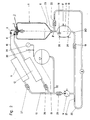
- An essentially cylindrical to spherical pressure vessel 1 according to FIG. 1 has an injection opening on its upper side 2, one directed into the interior of the pressure vessel Has spray and atomizer nozzle 3. Via assigned valves 4 can alternately hot water or in the pressure vessel 1 Cold water can be sprayed.
- the pressure vessel filled with a gas or a gas mixture 1 is in its wall with a displaceable piston 5 connected, the connection to an arrangement 9 for converting thermal energy, especially a hot water engine, manufactures.
- the pressure vessel 1 is funnel-shaped at its lower section 6 formed in a pressure vessel 1 after below swamp 7 merges with its lower one End has a controllable lower water drain opening 8.
- the pressure vessel 1 In order to heat the air or other gases of the pressure container 1, becomes hot water directly via the assigned valve 4 and the injection opening 2 via the spray nozzle 3 into the pressure vessel sprayed where there is gas to expand immediately largely permeated.
- the pressure vessel 1 is at least inside, otherwise insulated so that there is no heat in the material.
- the inner wall is water-repellent, around the water introduced after cooling quickly to derive down.
- the air warms up with the spraying of warm water, expands and performs on the sliding piston 5 work, which is a working cycle not shown 20 of the arrangement 9 for converting the thermal energy is fed.
- the warm water is sprayed so that the heat or cold brought in the water can spread directly in the container. This ensures a high clock frequency (approx. one cycle in one up to three seconds).
- the amount of water required for heating is very small. It is enough to heat 100 liters of air from 0 ° C to 100 ° C 9.1 kJ in 22 g of water. This is a useful work from 3.6 kJ available (approx. 40% efficiency when using Air).
- Valves 4 assigned, the one valve 4 via a connecting line 10 with a cooling device 11 for generation of the cold water and the other valve 4 also via one Connection line 10 with a heating device 12 for generation of the hot water is coupled. Both the warm and the cold water enter a separate injection opening 2 each with associated spray and atomizing nozzle 3.
- the cooling device 11 and the heating device 12 are via a corresponding branching line 13 from one Pump 14 fed, the line 13 with an expansion tank 15 is connected.
- line 13 is immediate before the cooling device 11 and the heating device 12 a check valve 27, 26 is used, the check valves 27, 26 an outflow of the appropriately tempered Water from the cooling device 11 or the heating device 12 prevent.
- a check valve 25 between the pump 14 and an inlet 32 of the expansion tank 15 provided to the line 13.
- the expansion tank 15 protrudes an inlet valve 30 with a corresponding water supply in connection.
- the expansion tank 15 is a Pressure sensor 31 coupled to the pump 14.
- the pressure vessel 1 On the underside of the pressure vessel 1 according to FIG. 2 is one arranged with water 16 filled liquid piston pump 17, the on the input side with a water inlet 23 of the working circuit 20 coupled water outlet opening 8 of the pressure vessel 1 and on the output side with a water outlet 33 of the Working circuit 20 is connected.
- the water 16 in the Liquid piston pump 17 pressurized accordingly and the Level 18 reaches a lower end position by a level sensor 29 is monitored, the end of the spraying phase controls the hot water.
- the condensate or waste water accumulating in the pressure vessel reaches the working circuit via the liquid piston pump 17 20, which is coupled to the pump 14, which in turn by a corresponding control by the pressure sensor 31 of the Expansion tank 15, the waste water of the cooling device 11, the Heater 12 and the expansion tank 15 supplies.
- the valves 4, the level sensors, can be used to control the processes 28, 29 of the liquid piston pump 17, the pressure sensor 31 of the expansion tank 17 and / or the pump 14 with a computer, not shown, which is responsible for the injection processes, the level 18 and the pressure monitored and controls the previously listed components accordingly.
Landscapes
- Engineering & Computer Science (AREA)
- Combustion & Propulsion (AREA)
- Mechanical Engineering (AREA)
- General Engineering & Computer Science (AREA)
- Chemical & Material Sciences (AREA)
- Engine Equipment That Uses Special Cycles (AREA)
- Jet Pumps And Other Pumps (AREA)
- Crystals, And After-Treatments Of Crystals (AREA)
- Nozzles (AREA)
- Glass Compositions (AREA)
- Carbon And Carbon Compounds (AREA)
- Control Of Electric Motors In General (AREA)
- Cooling Or The Like Of Electrical Apparatus (AREA)
- Transition And Organic Metals Composition Catalysts For Addition Polymerization (AREA)
- Filling Or Discharging Of Gas Storage Vessels (AREA)
- Iron Core Of Rotating Electric Machines (AREA)
- Compositions Of Oxide Ceramics (AREA)
- Motor Or Generator Frames (AREA)
Claims (7)
- Élément d'expansion de gaz pour un agencement (9) pour convertir de l'énergie thermique en énergie motrice, en particulier pour un moteur à eau chaude, constitué d'un récipient sous pression fermé (1) qui est rempli d'un gaz ou d'un mélange de gaz et qui est relié activement à l'agencement par l'intermédiaire d'un piston coulissant (5) et comporte une ouverture haute d'injection (2) pour de l'eau chaude ainsi qu'une ouverture basse d'évacuation d'eau (8), et le récipient sous pression (1) comportant une ouverture haute d'injection (2) pour de l'eau froide, caractérisé en ce quel'ouverture basse d'évacuation d'eau (8) est disposée à l'extrémité inférieure d'une partie de fond (7) saillant vers le bas qui possède un diamètre nettement inférieur au récipient sous pression (1), etle piston (5) étant conformé en pompe à piston liquide (17) qui est reliée, côté entrée, à l'ouverture d'évacuation d'eau (8) du récipient sous pression (1), à laquelle est associée une arrivée d'eau (23) d'un circuit de travail (20), et, côté sortie, à une évacuation d'eau (33) du circuit de travail (20).
- Élément d'expansion de gaz selon la revendication 1, caractérisé en ce que, pour l'eau chaude et l'eau froide, il est prévu à chaque fois une ouverture d'injection (2) avec une buse de pulvérisation et de vaporisation (3) orientée vers l'intérieur du récipient sous pression (1).
- Élément d'expansion de gaz selon la revendication 1 ou 2, caractérisé en ce qu'au moins la paroi intérieure du récipient sous pression (1) est constituée d'un matériau non endothermique ou est revêtue d'une matière isolante.
- Élément d'expansion de gaz selon une des revendications 1 à 3, caractérisé en ce que la paroi intérieure du récipient sous pression (1) est constituée d'un matériau hydrofuge ou est revêtue d'un tel matériau.
- Élément d'expansion de gaz selon la revendication 1, caractérisé en ce que la pompe à piston liquide (17) est munie d'un capteur de niveau (28, 29) respectivement pour un niveau haut et pour un niveau bas (18) de l'eau à l'intérieur de la pompe à piston liquide (17).
- Élément d'expansion de gaz selon la revendication 1, caractérisé en ce qu'une soupape antiretour (19, 22) est implantée respectivement sur l'évacuation d'eau (8) et sur l'arrivée d'eau (23).
- Élément d'expansion de gaz selon une des revendications 1 à 6, caractérisé en ce que le récipient sous pression (1) est conformé avec une transition en entonnoir avec la partie de fond (7), respectivement en direction de l'arrivée d'eau (23).
Applications Claiming Priority (3)
| Application Number | Priority Date | Filing Date | Title |
|---|---|---|---|
| DE19909611 | 1999-03-05 | ||
| DE19909611A DE19909611C1 (de) | 1999-03-05 | 1999-03-05 | Gasausdehnungselement für eine Anordnung zum Umwandeln von thermischer in motorische Energie, insbesondere für einen Warmwassermotor |
| PCT/DE2000/000642 WO2000053898A1 (fr) | 1999-03-05 | 2000-03-04 | Element d'expansion de gaz conçu pour un dispositif de transformation d'energie thermique en energie motrice, notamment pour un moteur a eau chaude |
Publications (2)
| Publication Number | Publication Date |
|---|---|
| EP1159512A1 EP1159512A1 (fr) | 2001-12-05 |
| EP1159512B1 true EP1159512B1 (fr) | 2003-10-08 |
Family
ID=7899758
Family Applications (1)
| Application Number | Title | Priority Date | Filing Date |
|---|---|---|---|
| EP00920368A Expired - Lifetime EP1159512B1 (fr) | 1999-03-05 | 2000-03-04 | Element d'expansion de gaz pour un dispositif de transformation d'energie thermique en energie motrice, notamment pour un moteur a eau chaude |
Country Status (10)
| Country | Link |
|---|---|
| US (1) | US6564551B1 (fr) |
| EP (1) | EP1159512B1 (fr) |
| JP (1) | JP2002539351A (fr) |
| AT (1) | ATE251713T1 (fr) |
| AU (1) | AU4098800A (fr) |
| DE (3) | DE19909611C1 (fr) |
| DK (1) | DK1159512T3 (fr) |
| ES (1) | ES2208307T3 (fr) |
| PT (1) | PT1159512E (fr) |
| WO (1) | WO2000053898A1 (fr) |
Cited By (1)
| Publication number | Priority date | Publication date | Assignee | Title |
|---|---|---|---|---|
| WO2005071232A1 (fr) * | 2004-01-24 | 2005-08-04 | Gerhard Stock | Ensemble servant a transformer de l'energie thermique en energie motrice |
Families Citing this family (16)
| Publication number | Priority date | Publication date | Assignee | Title |
|---|---|---|---|---|
| GB2376507A (en) * | 2001-05-03 | 2002-12-18 | S & C Thermofluids Ltd | An engine where the working gases in the cylinder are heated by injection of hot liquid |
| DE10133153C1 (de) | 2001-07-07 | 2002-07-11 | Gerhard Stock | Anordnung von Gasausdehnungselementen und Verfahren zum Betreiben der Anordnung |
| DE10209998B4 (de) * | 2002-03-07 | 2004-04-08 | Gerhard Stock | Gasausdehnungselement für eine Anordnung zum Umwandeln von thermischer in motorische Energie |
| DE10236749A1 (de) * | 2002-08-10 | 2004-02-19 | Arnold Berdel | Verfahren zur Energieumwandlung und Vorrichtung dazu |
| GB0725200D0 (en) * | 2007-12-24 | 2008-01-30 | Heptron Ltd | Power conversion apparatus |
| EP2379884A4 (fr) * | 2008-12-22 | 2015-09-30 | Exencotech Ab | Cellule énergétique |
| US8096118B2 (en) * | 2009-01-30 | 2012-01-17 | Williams Jonathan H | Engine for utilizing thermal energy to generate electricity |
| US8146354B2 (en) * | 2009-06-29 | 2012-04-03 | Lightsail Energy, Inc. | Compressed air energy storage system utilizing two-phase flow to facilitate heat exchange |
| US8247915B2 (en) * | 2010-03-24 | 2012-08-21 | Lightsail Energy, Inc. | Energy storage system utilizing compressed gas |
| US8436489B2 (en) * | 2009-06-29 | 2013-05-07 | Lightsail Energy, Inc. | Compressed air energy storage system utilizing two-phase flow to facilitate heat exchange |
| US8196395B2 (en) | 2009-06-29 | 2012-06-12 | Lightsail Energy, Inc. | Compressed air energy storage system utilizing two-phase flow to facilitate heat exchange |
| DE102010005232A1 (de) | 2010-01-21 | 2011-09-08 | Gerhard Stock | Anordnung zum Umwandeln von thermischer in motorische Energie |
| DE102010022088A1 (de) * | 2010-05-31 | 2011-12-01 | Peter Wolf | Grundlastfähiges Energiespeicherkraftwerk mit Brauchwasseraufbereitung |
| KR20130095421A (ko) * | 2012-02-20 | 2013-08-28 | 삼성전자주식회사 | 전구물질 기화 장치 및 이를 이용한 막 형성 방법 |
| PL240516B1 (pl) * | 2018-01-09 | 2022-04-19 | Dobrianski Jurij | Maszyna parowa |
| US11125183B1 (en) * | 2020-08-04 | 2021-09-21 | Navita Energy, Inc. | Effective low temperature differential powered engines, systems, and methods |
Family Cites Families (9)
| Publication number | Priority date | Publication date | Assignee | Title |
|---|---|---|---|---|
| US3932995A (en) * | 1971-04-17 | 1976-01-20 | Milan Pecar | System for producing work using a small temperature differential |
| FR2233871A5 (fr) * | 1973-06-14 | 1975-01-10 | Mengin Ets Pierre | |
| US4107928A (en) * | 1975-08-12 | 1978-08-22 | American Solar King Corporation | Thermal energy method and machine |
| US4283915A (en) | 1976-04-14 | 1981-08-18 | David P. McConnell | Hydraulic fluid generator |
| US4545207A (en) * | 1978-04-10 | 1985-10-08 | Neary Michael P | Solar energy system |
| EP0043879A3 (fr) * | 1980-07-16 | 1982-08-11 | Thermal Systems Limited. | Machine motrice à combustion externe à piston alternatif et méthode pour faire fonctionner cette machine |
| US4748813A (en) * | 1985-06-23 | 1988-06-07 | The Board Of Trustees Of The Leland Stanford Junior University | Method of operating a thermal engine powered by a chemical reaction |
| US5074110A (en) | 1990-10-22 | 1991-12-24 | Satnarine Singh | Combustion engine |
| DE19719190C2 (de) | 1997-05-08 | 1999-02-25 | Gerhard Stock | Warmwassermotor zur Wandlung von thermischer in elektrische Energie |
-
1999
- 1999-03-05 DE DE19909611A patent/DE19909611C1/de not_active Expired - Fee Related
-
2000
- 2000-03-04 US US09/914,766 patent/US6564551B1/en not_active Expired - Fee Related
- 2000-03-04 JP JP2000604101A patent/JP2002539351A/ja not_active Withdrawn
- 2000-03-04 WO PCT/DE2000/000642 patent/WO2000053898A1/fr not_active Ceased
- 2000-03-04 AT AT00920368T patent/ATE251713T1/de not_active IP Right Cessation
- 2000-03-04 DK DK00920368T patent/DK1159512T3/da active
- 2000-03-04 DE DE50003997T patent/DE50003997D1/de not_active Expired - Fee Related
- 2000-03-04 DE DE10080564T patent/DE10080564D2/de not_active Expired - Lifetime
- 2000-03-04 EP EP00920368A patent/EP1159512B1/fr not_active Expired - Lifetime
- 2000-03-04 AU AU40988/00A patent/AU4098800A/en not_active Abandoned
- 2000-03-04 PT PT00920368T patent/PT1159512E/pt unknown
- 2000-03-04 ES ES00920368T patent/ES2208307T3/es not_active Expired - Lifetime
Cited By (1)
| Publication number | Priority date | Publication date | Assignee | Title |
|---|---|---|---|---|
| WO2005071232A1 (fr) * | 2004-01-24 | 2005-08-04 | Gerhard Stock | Ensemble servant a transformer de l'energie thermique en energie motrice |
Also Published As
| Publication number | Publication date |
|---|---|
| ES2208307T3 (es) | 2004-06-16 |
| JP2002539351A (ja) | 2002-11-19 |
| AU4098800A (en) | 2000-09-28 |
| DE10080564D2 (de) | 2002-02-14 |
| WO2000053898A1 (fr) | 2000-09-14 |
| DE50003997D1 (de) | 2003-11-13 |
| US6564551B1 (en) | 2003-05-20 |
| EP1159512A1 (fr) | 2001-12-05 |
| ATE251713T1 (de) | 2003-10-15 |
| DE19909611C1 (de) | 2000-04-06 |
| DK1159512T3 (da) | 2004-02-09 |
| PT1159512E (pt) | 2004-02-27 |
Similar Documents
| Publication | Publication Date | Title |
|---|---|---|
| EP1159512B1 (fr) | Element d'expansion de gaz pour un dispositif de transformation d'energie thermique en energie motrice, notamment pour un moteur a eau chaude | |
| DE102008001308B3 (de) | Wärmeenergiemanagement für Produktionsanlagen | |
| DE102010005232A1 (de) | Anordnung zum Umwandeln von thermischer in motorische Energie | |
| DE2219650A1 (de) | Destillierverfahren und Vorrichtung zur Durchfuhrung des Verfahrens | |
| EP1930558B1 (fr) | Convertisseur d'énergie | |
| DE3744487A1 (de) | Verfahren und vorrichtung zur foerderung von siedefaehigen fluessigkeiten | |
| EP1706601A1 (fr) | Ensemble servant a transformer de l'energie thermique en energie motrice | |
| DE10133153C1 (de) | Anordnung von Gasausdehnungselementen und Verfahren zum Betreiben der Anordnung | |
| EP0152931B1 (fr) | Procédé pour actionner une installation de chauffage à générateur-pompe de chaleur d'absorption pour le chauffage des locaux, la préparation d'eau chaude et pareil et installation de chauffage générateur-pompe de chaleur d'absorption | |
| DE112023000239T5 (de) | Wärmetauschkomponente und Wärmetauschverfahren für eine Hydriervorrichtung | |
| WO2012152602A1 (fr) | Circuit de conduite et procédé permettant de faire fonctionner un circuit de conduite destiné à récupérer la chaleur dissipée d'un moteur à combustion interne | |
| DE9201493U1 (de) | Energiesparende Kraft-Wärmekopplung | |
| WO1983002658A1 (fr) | Procede et dispositif d'exploitation d'une chaudiere a vapeur a haute pression | |
| EP1236011A1 (fr) | Dispositif refrigerant a absorption | |
| DE2402557A1 (de) | Kraftmaschine | |
| WO2006024182A2 (fr) | Procede et installation pour reguler un cycle de carnot | |
| DE10209998B4 (de) | Gasausdehnungselement für eine Anordnung zum Umwandeln von thermischer in motorische Energie | |
| DE102013013104B4 (de) | Wärmekraftmaschine | |
| DE3230821A1 (de) | Hub- oder rotationskraftmaschine sowie verfahren zum betrieb derselben | |
| EP1647768A1 (fr) | Système fermé pour la récupération de condensat et procédé fermé pour la récupération de condensat | |
| EP1146291A1 (fr) | Méthode et dispositif pour chauffer de l'eau sanitaire et/ou de l'eau de chauffage | |
| EP2375027B1 (fr) | Récipient d'équilibrage pour circuits de refroidissement | |
| DE19535479A1 (de) | Verfahren zur differenzierten Wärmeauskopplung aus einem Wärmepumpenkreislauf und Wärmepumpe zur Durchführung des Verfahrens | |
| DE19810978A1 (de) | Verfahren zum mehrstufigen Wärmepumpen mit Kompressor und Heißflüssigkeitsstrahlern in Zweikammerzyklonen ohne externe, bzw. alternativ mit einer solchen Wärmequelle | |
| DE29621539U1 (de) | Anlage zur Rückgewinnung von Wärme aus den Abgasen von Feuerungsanlagen oder Motoren |
Legal Events
| Date | Code | Title | Description |
|---|---|---|---|
| PUAI | Public reference made under article 153(3) epc to a published international application that has entered the european phase |
Free format text: ORIGINAL CODE: 0009012 |
|
| 17P | Request for examination filed |
Effective date: 20010920 |
|
| AK | Designated contracting states |
Kind code of ref document: A1 Designated state(s): AT BE CH CY DE DK ES FI FR GB GR IE IT LI LU MC NL PT SE |
|
| AX | Request for extension of the european patent |
Free format text: AL;LT;LV;MK;RO;SI |
|
| GRAH | Despatch of communication of intention to grant a patent |
Free format text: ORIGINAL CODE: EPIDOS IGRA |
|
| GRAS | Grant fee paid |
Free format text: ORIGINAL CODE: EPIDOSNIGR3 |
|
| GRAA | (expected) grant |
Free format text: ORIGINAL CODE: 0009210 |
|
| AK | Designated contracting states |
Kind code of ref document: B1 Designated state(s): AT BE CH CY DE DK ES FI FR GB GR IE IT LI LU MC NL PT SE |
|
| REG | Reference to a national code |
Ref country code: GB Ref legal event code: FG4D Free format text: NOT ENGLISH |
|
| REG | Reference to a national code |
Ref country code: CH Ref legal event code: EP |
|
| REG | Reference to a national code |
Ref country code: IE Ref legal event code: FG4D Free format text: GERMAN |
|
| REF | Corresponds to: |
Ref document number: 50003997 Country of ref document: DE Date of ref document: 20031113 Kind code of ref document: P |
|
| REG | Reference to a national code |
Ref country code: SE Ref legal event code: TRGR |
|
| REG | Reference to a national code |
Ref country code: CH Ref legal event code: NV Representative=s name: PA ALDO ROEMPLER |
|
| REG | Reference to a national code |
Ref country code: DK Ref legal event code: T3 |
|
| GBT | Gb: translation of ep patent filed (gb section 77(6)(a)/1977) |
Effective date: 20040126 |
|
| PGFP | Annual fee paid to national office [announced via postgrant information from national office to epo] |
Ref country code: CY Payment date: 20040220 Year of fee payment: 5 |
|
| REG | Reference to a national code |
Ref country code: GR Ref legal event code: EP Ref document number: 20040400053 Country of ref document: GR |
|
| LTIE | Lt: invalidation of european patent or patent extension |
Effective date: 20031008 |
|
| REG | Reference to a national code |
Ref country code: ES Ref legal event code: FG2A Ref document number: 2208307 Country of ref document: ES Kind code of ref document: T3 |
|
| ET | Fr: translation filed | ||
| PLBE | No opposition filed within time limit |
Free format text: ORIGINAL CODE: 0009261 |
|
| STAA | Information on the status of an ep patent application or granted ep patent |
Free format text: STATUS: NO OPPOSITION FILED WITHIN TIME LIMIT |
|
| 26N | No opposition filed |
Effective date: 20040709 |
|
| PGFP | Annual fee paid to national office [announced via postgrant information from national office to epo] |
Ref country code: IE Payment date: 20050216 Year of fee payment: 6 |
|
| PGFP | Annual fee paid to national office [announced via postgrant information from national office to epo] |
Ref country code: AT Payment date: 20050218 Year of fee payment: 6 |
|
| PGFP | Annual fee paid to national office [announced via postgrant information from national office to epo] |
Ref country code: GB Payment date: 20050221 Year of fee payment: 6 |
|
| PGFP | Annual fee paid to national office [announced via postgrant information from national office to epo] |
Ref country code: BE Payment date: 20050228 Year of fee payment: 6 |
|
| PG25 | Lapsed in a contracting state [announced via postgrant information from national office to epo] |
Ref country code: IT Free format text: LAPSE BECAUSE OF NON-PAYMENT OF DUE FEES Effective date: 20050304 Ref country code: CY Free format text: LAPSE BECAUSE OF NON-PAYMENT OF DUE FEES Effective date: 20050304 |
|
| PGFP | Annual fee paid to national office [announced via postgrant information from national office to epo] |
Ref country code: PT Payment date: 20050304 Year of fee payment: 6 |
|
| PGFP | Annual fee paid to national office [announced via postgrant information from national office to epo] |
Ref country code: ES Payment date: 20050308 Year of fee payment: 6 |
|
| PGFP | Annual fee paid to national office [announced via postgrant information from national office to epo] |
Ref country code: FI Payment date: 20050311 Year of fee payment: 6 |
|
| PGFP | Annual fee paid to national office [announced via postgrant information from national office to epo] |
Ref country code: DK Payment date: 20050314 Year of fee payment: 6 |
|
| PGFP | Annual fee paid to national office [announced via postgrant information from national office to epo] |
Ref country code: SE Payment date: 20050316 Year of fee payment: 6 Ref country code: LU Payment date: 20050316 Year of fee payment: 6 |
|
| PGFP | Annual fee paid to national office [announced via postgrant information from national office to epo] |
Ref country code: MC Payment date: 20050317 Year of fee payment: 6 |
|
| PGFP | Annual fee paid to national office [announced via postgrant information from national office to epo] |
Ref country code: FR Payment date: 20050322 Year of fee payment: 6 |
|
| PGFP | Annual fee paid to national office [announced via postgrant information from national office to epo] |
Ref country code: NL Payment date: 20050331 Year of fee payment: 6 Ref country code: GR Payment date: 20050331 Year of fee payment: 6 |
|
| PGFP | Annual fee paid to national office [announced via postgrant information from national office to epo] |
Ref country code: DE Payment date: 20050524 Year of fee payment: 6 |
|
| PGFP | Annual fee paid to national office [announced via postgrant information from national office to epo] |
Ref country code: CH Payment date: 20050622 Year of fee payment: 6 |
|
| PG25 | Lapsed in a contracting state [announced via postgrant information from national office to epo] |
Ref country code: GB Free format text: LAPSE BECAUSE OF NON-PAYMENT OF DUE FEES Effective date: 20060304 Ref country code: FI Free format text: LAPSE BECAUSE OF NON-PAYMENT OF DUE FEES Effective date: 20060304 Ref country code: AT Free format text: LAPSE BECAUSE OF NON-PAYMENT OF DUE FEES Effective date: 20060304 |
|
| PG25 | Lapsed in a contracting state [announced via postgrant information from national office to epo] |
Ref country code: SE Free format text: LAPSE BECAUSE OF NON-PAYMENT OF DUE FEES Effective date: 20060305 |
|
| PG25 | Lapsed in a contracting state [announced via postgrant information from national office to epo] |
Ref country code: IE Free format text: LAPSE BECAUSE OF NON-PAYMENT OF DUE FEES Effective date: 20060306 Ref country code: ES Free format text: LAPSE BECAUSE OF NON-PAYMENT OF DUE FEES Effective date: 20060306 |
|
| PG25 | Lapsed in a contracting state [announced via postgrant information from national office to epo] |
Ref country code: MC Free format text: LAPSE BECAUSE OF NON-PAYMENT OF DUE FEES Effective date: 20060331 Ref country code: LU Free format text: LAPSE BECAUSE OF NON-PAYMENT OF DUE FEES Effective date: 20060331 Ref country code: LI Free format text: LAPSE BECAUSE OF NON-PAYMENT OF DUE FEES Effective date: 20060331 Ref country code: DK Free format text: LAPSE BECAUSE OF NON-PAYMENT OF DUE FEES Effective date: 20060331 Ref country code: CH Free format text: LAPSE BECAUSE OF NON-PAYMENT OF DUE FEES Effective date: 20060331 Ref country code: BE Free format text: LAPSE BECAUSE OF NON-PAYMENT OF DUE FEES Effective date: 20060331 |
|
| PG25 | Lapsed in a contracting state [announced via postgrant information from national office to epo] |
Ref country code: PT Free format text: LAPSE BECAUSE OF NON-PAYMENT OF DUE FEES Effective date: 20060904 |
|
| PG25 | Lapsed in a contracting state [announced via postgrant information from national office to epo] |
Ref country code: NL Free format text: LAPSE BECAUSE OF NON-PAYMENT OF DUE FEES Effective date: 20061001 |
|
| PG25 | Lapsed in a contracting state [announced via postgrant information from national office to epo] |
Ref country code: DE Free format text: LAPSE BECAUSE OF NON-PAYMENT OF DUE FEES Effective date: 20061003 |
|
| REG | Reference to a national code |
Ref country code: DK Ref legal event code: EBP |
|
| REG | Reference to a national code |
Ref country code: PT Ref legal event code: MM4A Effective date: 20060904 |
|
| REG | Reference to a national code |
Ref country code: CH Ref legal event code: PL |
|
| EUG | Se: european patent has lapsed | ||
| GBPC | Gb: european patent ceased through non-payment of renewal fee |
Effective date: 20060304 |
|
| NLV4 | Nl: lapsed or anulled due to non-payment of the annual fee |
Effective date: 20061001 |
|
| REG | Reference to a national code |
Ref country code: IE Ref legal event code: MM4A |
|
| REG | Reference to a national code |
Ref country code: FR Ref legal event code: ST Effective date: 20061130 |
|
| REG | Reference to a national code |
Ref country code: ES Ref legal event code: FD2A Effective date: 20060306 |
|
| BERE | Be: lapsed |
Owner name: *STOCK GERHARD Effective date: 20060331 |
|
| PG25 | Lapsed in a contracting state [announced via postgrant information from national office to epo] |
Ref country code: FR Free format text: LAPSE BECAUSE OF NON-PAYMENT OF DUE FEES Effective date: 20060331 |
|
| PG25 | Lapsed in a contracting state [announced via postgrant information from national office to epo] |
Ref country code: GR Free format text: LAPSE BECAUSE OF NON-PAYMENT OF DUE FEES Effective date: 20061002 |