EP1160026A2 - Verfahren zur Herstellung eines Streckgitters sowie ein mit diesem Verfahren hergestelltes Streckgitter - Google Patents
Verfahren zur Herstellung eines Streckgitters sowie ein mit diesem Verfahren hergestelltes Streckgitter Download PDFInfo
- Publication number
- EP1160026A2 EP1160026A2 EP01113319A EP01113319A EP1160026A2 EP 1160026 A2 EP1160026 A2 EP 1160026A2 EP 01113319 A EP01113319 A EP 01113319A EP 01113319 A EP01113319 A EP 01113319A EP 1160026 A2 EP1160026 A2 EP 1160026A2
- Authority
- EP
- European Patent Office
- Prior art keywords
- stretching
- material web
- stretched
- incisions
- expanded metal
- Prior art date
- Legal status (The legal status is an assumption and is not a legal conclusion. Google has not performed a legal analysis and makes no representation as to the accuracy of the status listed.)
- Withdrawn
Links
Images





Classifications
-
- B—PERFORMING OPERATIONS; TRANSPORTING
- B21—MECHANICAL METAL-WORKING WITHOUT ESSENTIALLY REMOVING MATERIAL; PUNCHING METAL
- B21D—WORKING OR PROCESSING OF SHEET METAL OR METAL TUBES, RODS OR PROFILES WITHOUT ESSENTIALLY REMOVING MATERIAL; PUNCHING METAL
- B21D31/00—Other methods for working sheet metal, metal tubes, metal profiles
- B21D31/04—Expanding other than provided for in groups B21D1/00 - B21D28/00, e.g. for making expanded metal
- B21D31/043—Making use of slitting discs or punch cutters
Definitions
- the invention relates to a method for producing a Expanded mesh according to the preamble of claim 1 and a Expanded mesh produced by this process.
- Expanded mesh is a web of material preferably made of metal, in which a variety of cuts introduced parallel to each other and then laterally across Direction of the incisions is pulled apart.
- a metal strip over a Guide conveyor with a cutting device during of the conveying process cuts into the metal strip, whose cutting lines are either parallel or transverse to Direction of conveyance.
- the incisions are in straight lines Rows introduced and offset in successive rows arranged to each other.
- For incisions that are parallel to Direction of conveyance have been introduced into the metal strip are in the two side edges of a downstream stretching device of the metal strip during the conveying process and after pulled outside, so that the metal band transversely to the conveying direction is stretched. This creates a expanded metal, the Final width is larger than its initial width.
- EP 0 599 782 A1 shows the closest prior art a process for producing a expanded metal, in which the Incisions in the metal belt across the conveying direction be introduced. These incisions are in rows across Direction of conveying introduced and in successive rows staggered.
- the sheet metal strip is now continuous at a first speed through a first Funding and with one in relation to the first Speed increased by a second speed second funding. This will make the between first and second conveyor belt section below Formation of a three-dimensional expanded metal structure.
- the production is based on the plastic deformability of the Material web, the one formed between the incisions Horizontal stripes or grid web of the web on a required Dimension is stretched by making the metal not only inelastic bent, but also stretched.
- the funds are available via projections or pins that are arranged on rollers, and with which they also get into the material web engage holes and thereby the material web hold on so that the material web is stretched without slip can. Since the expanded metal is in its way during the stretching process Contracting width, it is necessary that Intervention devices differ from roller to roller spaced so that a stitch formed during stretching is exact is gripped by an engaging pin or the like.
- the object of the invention is now a Manufacturing process for expanded metal, in particular from one To show soft metal, which has the disadvantages mentioned above eliminated and with which a expanded metal can be produced can't do that after stretching Recrystallization process, especially soft annealing must be subjected.
- it is a job of Invention, a method of manufacturing softer To show expanded metal grids with the extended angle of far over 90 ° are possible.
- the basis of the method according to the invention is that the material web is positively guided only in the stretching direction. This means that the web can contract freely in its width during the stretching process. The degree of width contraction is determined solely by the force exerted to stretch the material web. This enables stretching, with which stretching of the material can be prevented and the material retains its material properties in unchanged form.
- the intermediate webs remain unstretched and they are essentially only slightly bent in the region of the knots, so that they retain their plastic deformability and corrosion resistance.
- the invention thus enables flawless metal nets provided with diamond-shaped or rhombic meshes to be produced, in which a change in the metallurgical properties of the webs delimiting the meshes as a result of stretching is avoided.
- the method is advantageously suitable for processing soft metals, since the protection of materials plays an important role here because soft metals are more susceptible to stretching with regard to their material properties to be preserved.
- the method according to the invention it is possible to produce expanded metal with a larger angle.
- the method of the invention also significantly reduces the manufacturing cost of expanded metal.
- the material web is conveyed between two smooth conveyor rollers, so that it is ensured that the contraction in width is not limited by interventions in the web.
- Pins or teeth can also be provided, which engage in the mesh openings or in additionally introduced holes during the stretching process, so that the material web is held securely and without slippage. These pins or teeth are then held in such a way that their mutual spacing can adapt to the width contraction of the material web transversely to the direction of stretch.
- the expanded metal can be produced in one Process step that involves cutting and on the other hand includes the stretching of the material web.
- the incisions are made transversely to the conveying direction and the Material web stretched in the conveying direction.
- the manufacture can but also in the two separate process steps of cutting or stretching be separated from each other in time and / or location expire.
- the incised and undrawn material can then be wound on spools, rolls or cores and a stretching process at another time be subjected.
- This solution has the advantage that the wound coil can be transported in a compact form, whereby less space is required and the material itself is less susceptible to damage.
- Fig. 1 shows a metal track section 1 with parallel Incisions 2a of the same length is provided.
- the incisions are staggered in successive rows arranged. The distance left between them defines the Lattice nodes 3.
- Fig. 2 shows the incised web section of the Fig. 1 in an already stretched form.
- the incisions 2a increase to open stitches 2b.
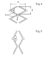
- the widening of the mesh and the associated The expanded metal is extended without stretching the Starting material, which means that the increase in Mesh width b causes a reduction in mesh length 1 (see Fig. 4).
- the total width of the Expanded mesh Like that from FIG. 2 in comparison to FIG. 1 can be seen, the total width of the Expanded mesh.
- Fig. 3 shows the expanded metal from Fig. 2 in plan view another stretch.
- the mesh opening 2c still has here once increased without stretching the starting material.
- the nodes 3 bend out of the metal track level, which creates a three-dimensional profiled expanded metal sheet results.
- the stretching is Metal web possible without an expansion of the bars 7 because through the free contracting of the web, these lattice webs 7 only in the transition areas 4 from the webs 7 to Lattice nodes 3 experience a deflection. While at the conventional expanded metal fabrication through the mesh length 1 the yield strength of the starting material is limited, so that the Extension angle w is generally a maximum of 90 °, can be with the The inventive method a expanded metal made of soft metal with much larger stretching angles w of up to 180 ° getting produced.
- Fig. 5 shows a mesh of the more stretched expanded metal with a correspondingly enlarged stretching angle w in two dimensions Illustration.
- the figure shows how the Enlargement of the stretching angle w and the associated angle Increasing the mesh length 1 decreases the mesh width b.
- the length of the mesh webs 7 is retained, which is Using, for example, a expanded metal made of soft Aluminum means that its metallurgical properties not be changed by the stretching process and that Aluminum undergoes essentially no hardening.
- the defined mesh formation happens either 6 immediately after the incision by two take-off rollers 9a and 9b, which after the cutting tool 10 are arranged, the cut sheet 1 with a Pulling speed higher than the speed of the Feed rollers 8a and 8b.
- A indicates the conveying direction of the Metal track.
- Fig. 7 describes the production with two separate Cutting tools.
- Two feed rollers 20a and 20b do this Material 21 to the first cutting tool 22a with the Hold-down 23a and the cutting plate 24a.
- the second cutting tool 22b also closes behind it Hold-down 23b and insert 24b.
- the insert 24b connects seamlessly to the cutting plate 24a and is just up to the small recess 25 that the working stroke of allows first cutting tool 22a.
- FIG. 8 shows the incised material 26 accordingly first cutting tool 22a produces the cuts 27a and that second cutting tool 22b the incisions 27b. Since the Incisions 27a only slit the material 21 in such a way that continuous strips 28 remain, the one Prevent these incisions 27a from pulling apart Feed also between the two cutting tools 22a and 22b respectively. This possibility is in Fig. 7 with the Feed rollers 29a and 29b indicated.
- Fig. 9 shows the arrangement of two sawtooth-shaped Rotary knives 30a and 30b that are continuous Production using the roll cut method according to FIG. 1 enable. Are in a continuous process Production speeds of 50-100 m / min achievable, while the conventional expanded metal cut the Production speed limited to 0.5 - 1.5 m / min.
- Fig. 10 is the meshing of the individual teeth 31a and 31b of the rotary knives 30a and 30b.
- Fig. 11 shows the knife disks 32 arranged perpendicular to the conveying direction with teeth 31a or 31b and knife disks 33, each of which second tooth is omitted, as in Fig. 10 by the dashed Lines 34 is shown.
Landscapes
- Engineering & Computer Science (AREA)
- Mechanical Engineering (AREA)
- Cell Electrode Carriers And Collectors (AREA)
- Metal Rolling (AREA)
Abstract
Die Materialbahn (1) kontrahiert in ihrer Breite während des Streckvorgangs auf ein Maß, das nur durch die während des Streckvorgangs auf die Materialbahn ausgeübte Streckkraft bestimmt ist.
Description
Diesbezüglich eignet sich das Verfahren vorteilhaft für die Verarbeitung von weichen Metallen, da die Materialschonung hier eine bedeutende Rolle spielt, weil weiche Metalle hinsichtlich ihrer zu konservierenden Materialeigenschaften anfälliger auf eine Streckung reagieren.
Mit dem erfindungsgemäßen Verfahren ist es möglich, Streckgitter mit größerem Streckwinkel herzustellen. Durch das Verfahren der Erfindung werden auch die Herstellungskosten eines Streckgitters bedeutend reduziert.
In einer vorteilhaften Weiterbildung wird die Materialbahn zwischen zwei glatten Förderwalzen gefördert, so daß gewährleistet ist, daß das Zusammenziehen in der Breite nicht durch Eingriffe in die Bahn begrenzt wird.
Es können auch Stifte oder Zähne vorgesehen sein, die während des Streckvorgangs in die Maschenöffnungen oder in zusätzlich eingebrachte Löcher eingreifen, damit die Materialbahn sicher und schlupffrei gehalten wird. Diese Stifte bzw. Zähne sind dann so gehalten, daß sich ihr gegenseitiger Abstand quer zur Streckrichung der Breitenkontraktion der Materialbahn von alleine anpassen kann.
- Fig. 1
- eine Draufsicht auf einen mit versetzten Einschnitten versehenen, noch ungestreckten Metallbahnabschnitt,
- Fig. 2
- eine Draufsicht auf einen aus dem Metallbahnabschnitt von Fig. 1 gebildeten Streckgitterabschnitt,
- Fig. 3
- eine weitere Draufsicht des stärker gestreckten Materialbahnabschnittes von Fig. 2,
- Fig. 4
- einen vergrößerten Ausschnitt des gestreckten Gitters aus einer Draufsicht,
- Fig. 5
- eine weitere Draufsicht des stärker gestreckten Gitters,
- Fig. 6
- die schematische Darstellung einer Vorrichtung zum Einschneiden und Strecken der Materialbahn,
- Fig. 7
- die schematisch Darstellung einer Vorrichtung zum Einschneiden der Materialbahn mit zwei hintereinanderliegenden Messern
- Fig. 8
- in Draufsicht das mit der Vorrichtung nach Fig. 7 eingeschnittene Material,
- Fig. 9
- die Anorndung von zwei Rotationsmessern zur Einbringung der Einschnitte im Rollschnittverfahren,
- Fig. 10
- die schematische Darstellung einer Herstellung im Rollschnittverfahren,
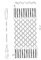
- Fig. 11
- ein Streckgitter mit plissierten Seitenrändern,
- Fig. 12 und 13
- ergänzende Darstellung von Messern aus Federbandstahl.
- Fig. 14 bis 16
- die schematische Darstellung einer Herstellung im Bandstahlverfahren.
Claims (10)
- Verfahren zur Herstellung eines Streckgitters, bei dem eine Materialbahn (1) mittels eines Schneidwerkzeuges mit parallel versetzten Einschnitten (2a) versehen und darauffolgend in einer quer zur Schnittlinie der Einschnitte gerichteten Richtung gestreckt wird, wodurch die Materialbahn (1) eine Längenänderung in der Streckrichtung (A) und eine Breitenreduzierung quer zur Streckrichtung erfährt und sich die Einschnitte (2a) zu Maschen (2b, 2c) öffnen,
dadurch gekennzeichnet, daß die Materialbahn (1) in ihrer Breite während des Streckvorgangs auf ein Maß kontrahiert, das durch die während des Streckvorgangs auf die Materialbahn ausgeübte Streckkraft bestimmt ist. - Verfahren nach Anspruch 1,
dadurch gekennzeichnet, dass die Materialbahn nach dem herkömmlichen Streckverfahren, d. h. unter Dehnung der Gitterstege geringfügig vorgestreckt wird. - Verfahren nach Anspruch 1 oder 2,
dadurch gekennzeichnet, daß die Materialbahn aus einem Weichmetall, z.B. Weichaluminium, besteht. - Verfahren nach einem Ansprüche 1 bis 3,
dadurch gekennzeichnet, daß die Materialbahn (1) zum Strecken zwischen glatte Walzen eingespannt wird. - Verfahren nach einem der Ansprüche 1 bis 3,
dadurch gekennzeichnet, daß die Materialbahn durch Eingriffvorrichtungen, wie beispielsweise Stifte, Noppen oder Zähne, gegriffen wird, die in die Maschenöffnungen oder zusätzlich eingebrachten Löcher eingreifen, wobei die Eingriffvorrichtungen so gehalten werden, daß sie die Materialbahn nur in der Streckrichtung zwangsführen und sie sich während des Streckvorganges quer zur Streckrichtung zueinander versetzen lassen. - Verfahren nach einem der vorangehenden Ansprüche,
dadurch gekennzeichnet, daß die Einschnitte in die Materialbahn (1) quer zur Streckrichtung (A) eingebracht werden. - Verfahren nach einem der vorangehenden Ansprüche,
dadurch gekennzeichnet, daß die Einschnitte durch Schneidwerkzeuge eingebracht werden, die auf rotierenden Schneidwalzen angeordnet sind. - Streckgitter nach dem Herstellungsverfahren des Anspruchs 1,
dadurch gekennzeichnet, daß das Material im wesentlichen keine Veränderungen seiner Material- oder Struktureigenschaften durch den Streckvorgang aufweist. - Streckgitter nach dem Herstellungsverfahren des Anspruch 2,
dadurch gekennzeichnet, dass das Material geringfügig vorgestreckt, d. h. in den Gitterstegen gedehnt ist und im übrigen im wesentlichen keine Veränderungen seiner Material-oder Struktureigenschaften durch den Streckvorgang aufweist. - Streckgitter nach Anspruch 8 oder 9,
dadurch gekennzeichnet, dass es in seinen nicht eingeschnittenen Randteilen (35,36) plissiert ist.
Applications Claiming Priority (2)
| Application Number | Priority Date | Filing Date | Title |
|---|---|---|---|
| DE10027010 | 2000-05-31 | ||
| DE2000127010 DE10027010C2 (de) | 2000-05-31 | 2000-05-31 | Verfahren zur Herstellung eines Streckgitters sowie ein mit diesem Verfahren hergestelltes Streckgitter |
Publications (2)
| Publication Number | Publication Date |
|---|---|
| EP1160026A2 true EP1160026A2 (de) | 2001-12-05 |
| EP1160026A3 EP1160026A3 (de) | 2002-10-23 |
Family
ID=7644244
Family Applications (1)
| Application Number | Title | Priority Date | Filing Date |
|---|---|---|---|
| EP01113319A Withdrawn EP1160026A3 (de) | 2000-05-31 | 2001-05-31 | Verfahren zur Herstellung eines Streckgitters sowie ein mit diesem Verfahren hergestelltes Streckgitter |
Country Status (2)
| Country | Link |
|---|---|
| EP (1) | EP1160026A3 (de) |
| DE (1) | DE10027010C2 (de) |
Cited By (2)
| Publication number | Priority date | Publication date | Assignee | Title |
|---|---|---|---|---|
| EP1537923A1 (de) * | 2003-12-06 | 2005-06-08 | GBA-Panek GmbH | Verfahren zur Herstellung von Streckgitterelementen |
| WO2010140966A1 (en) * | 2009-06-02 | 2010-12-09 | Ab Kompositprodukter | Visor and method for use in the production of such a visor |
Families Citing this family (2)
| Publication number | Priority date | Publication date | Assignee | Title |
|---|---|---|---|---|
| DE102017126315A1 (de) | 2017-11-09 | 2019-05-09 | GRAMMER Interior Components GmbH | Streckmetall mit Maschen unterschiedlicher Maschenform |
| DE102023131879A1 (de) * | 2023-11-15 | 2025-05-15 | STG Stanztechnik GmbH & Co. KG | Fertigungssystem und Verfahren zur Herstellung eines mit Durchbrüchen versehenen Metallbandes sowie Metallband |
Family Cites Families (8)
| Publication number | Priority date | Publication date | Assignee | Title |
|---|---|---|---|---|
| DE40543C (de) * | Eisenwerke Gaggenau, flürscheim & Bergmann in Gaggenau | Streckmaschine zur Herstellung von Blechgittern aus geschlitzten Blechen | ||
| US1103033A (en) * | 1906-01-12 | 1914-07-14 | Nat Metal Fabric Company | Apparatus for manufacturing expanded metal. |
| US1231888A (en) * | 1913-08-29 | 1917-07-03 | South Side Trust Company | Method of expanding stranded sheet metal. |
| AU469862B2 (en) * | 1972-08-23 | 1976-02-26 | Comalco (J.& S.) Pty. Ltd. | Expanded mesh |
| GB1470196A (en) * | 1974-11-13 | 1977-04-14 | Cooling Dev Ltd | Contact packing |
| DE8535675U1 (de) * | 1985-12-19 | 1987-09-10 | Braas & Co Gmbh, 6000 Frankfurt | Plastisch verformbare Abdeckvorrichtung |
| DE8816544U1 (de) * | 1988-05-10 | 1989-11-30 | Braas & Co GmbH, 6370 Oberursel | Dichtungsstreifen für eine First- oder Gratabdeckung |
| DE59307889D1 (de) * | 1992-11-24 | 1998-02-05 | Kuehni Ag | Verfahren und Vorrichtung zur Herstellung von Streckgittern |
-
2000
- 2000-05-31 DE DE2000127010 patent/DE10027010C2/de not_active Expired - Fee Related
-
2001
- 2001-05-31 EP EP01113319A patent/EP1160026A3/de not_active Withdrawn
Cited By (3)
| Publication number | Priority date | Publication date | Assignee | Title |
|---|---|---|---|---|
| EP1537923A1 (de) * | 2003-12-06 | 2005-06-08 | GBA-Panek GmbH | Verfahren zur Herstellung von Streckgitterelementen |
| WO2010140966A1 (en) * | 2009-06-02 | 2010-12-09 | Ab Kompositprodukter | Visor and method for use in the production of such a visor |
| US9265659B2 (en) | 2009-06-02 | 2016-02-23 | Ab Kompositprodukter | Expanded metal and process of making the same |
Also Published As
| Publication number | Publication date |
|---|---|
| DE10027010A1 (de) | 2001-12-13 |
| DE10027010C2 (de) | 2002-06-27 |
| EP1160026A3 (de) | 2002-10-23 |
Similar Documents
| Publication | Publication Date | Title |
|---|---|---|
| DE69935749T2 (de) | T-förmiges Profil mit zusammengenähtem Steg | |
| DE4400185B4 (de) | Verfahren und Vorrichtung zur Herstellung einer zwei Flansche und einen Steg aufweisenden Schiene für Hängedecken | |
| DE2943765C2 (de) | ||
| DE2549072C3 (de) | Vorrichtung zur Herstellung von Durchbrüchen in Bandmaterial aus Metallblech | |
| EP0599782A1 (de) | Verfahren und Vorrichtung zur Herstellung von Streckgittern | |
| EP1724409B1 (de) | Flächiges Metallelement und Profilelement | |
| DE68919540T2 (de) | Geschweisstes Drahtgitter mit verformten Streckdrähten und Verfahren zu seiner Herstellung. | |
| DE102009008356B4 (de) | Verfahren zur Herstellung von profilierten Blechen | |
| DE19545525C2 (de) | Verfahren zur Herstellung von Profilwalzelementen | |
| DE3020009A1 (de) | Vorrichtung fuer die herstellung von beuteln aus einer kunststoffolien-schlauchbahn | |
| DE2343579A1 (de) | Verfahren und vorrichtung zur formung eines metallstreifens mit laengs seiner breite unterschiedlicher dicke | |
| DE2740582A1 (de) | Verfahren und vorrichtung zur profilierung eines bandes aus elastoplastischem oder plastischem material | |
| DE19612239C2 (de) | Vorrichtung zur Herstellung eines randbereichsprofilierten Bleches, insbesondere aus einem ebenen Blech | |
| EP0492428A2 (de) | Vorrichtung zum Lochen von Bändern aus Folien oder Blech | |
| DE10027010C2 (de) | Verfahren zur Herstellung eines Streckgitters sowie ein mit diesem Verfahren hergestelltes Streckgitter | |
| DE102020201872A1 (de) | Käfigsegment für einen Wälzlagerkäfig | |
| EP0962269A2 (de) | Verfahren und Vorrichtung zur Herstellung von Bundlagern | |
| DE102019114443B4 (de) | Verfahren und Anlage zur Herstellung von Rahmenlängsträgern für Nutzfahrzeuge | |
| DE10357732B4 (de) | Verfahren zur Herstellung von Streckgitterelementen zur Errichtung von Zäunen sowie Zaunfeld aus einem Streckgitterelement | |
| EP1464526B1 (de) | Metallband als Einlage für Zier- oder Dichtstreifen | |
| DE10211257B4 (de) | Verfahren zum mechanischen Verbinden von zwei Elementen aus Metall, bei welchem die beiden Elemente aus Metall zwischen einem einzigen Satz von zwei Walzen hindurchgeführt werden | |
| DE60204888T2 (de) | Rotierendes standwerkzeug zum kontinuierlischen lochen von profilen sowie verwendung desselben | |
| DE2461246C3 (de) | Verfahren und Vorrichtung zur Herstellung von Durchbrüchen in Bandmaterial aus Metallblech | |
| DE4143035A1 (de) | Verfahren und vorrichtung zum herstellen von streckgitter aus duennem metallbandmaterial | |
| DE2438595A1 (de) | Band mit durchbruechen |
Legal Events
| Date | Code | Title | Description |
|---|---|---|---|
| PUAI | Public reference made under article 153(3) epc to a published international application that has entered the european phase |
Free format text: ORIGINAL CODE: 0009012 |
|
| AK | Designated contracting states |
Kind code of ref document: A2 Designated state(s): AT BE CH CY DE DK ES FI FR GB GR IE IT LI LU MC NL PT SE TR |
|
| AX | Request for extension of the european patent |
Free format text: AL;LT;LV;MK;RO;SI |
|
| PUAL | Search report despatched |
Free format text: ORIGINAL CODE: 0009013 |
|
| AK | Designated contracting states |
Kind code of ref document: A3 Designated state(s): AT BE CH CY DE DK ES FI FR GB GR IE IT LI LU MC NL PT SE TR |
|
| AX | Request for extension of the european patent |
Free format text: AL;LT;LV;MK;RO;SI |
|
| AKX | Designation fees paid | ||
| REG | Reference to a national code |
Ref country code: DE Ref legal event code: 8566 |
|
| STAA | Information on the status of an ep patent application or granted ep patent |
Free format text: STATUS: THE APPLICATION IS DEEMED TO BE WITHDRAWN |
|
| 18D | Application deemed to be withdrawn |
Effective date: 20030424 |