EP1160376A2 - Caisse aspirante pour machines à papier - Google Patents
Caisse aspirante pour machines à papier Download PDFInfo
- Publication number
- EP1160376A2 EP1160376A2 EP01113132A EP01113132A EP1160376A2 EP 1160376 A2 EP1160376 A2 EP 1160376A2 EP 01113132 A EP01113132 A EP 01113132A EP 01113132 A EP01113132 A EP 01113132A EP 1160376 A2 EP1160376 A2 EP 1160376A2
- Authority
- EP
- European Patent Office
- Prior art keywords
- suction box
- filtering surface
- opening
- section
- ducts
- Prior art date
- Legal status (The legal status is an assumption and is not a legal conclusion. Google has not performed a legal analysis and makes no representation as to the accuracy of the status listed.)
- Withdrawn
Links
Images

Classifications
-
- D—TEXTILES; PAPER
- D21—PAPER-MAKING; PRODUCTION OF CELLULOSE
- D21F—PAPER-MAKING MACHINES; METHODS OF PRODUCING PAPER THEREON
- D21F1/00—Wet end of machines for making continuous webs of paper
- D21F1/48—Suction apparatus
-
- D—TEXTILES; PAPER
- D21—PAPER-MAKING; PRODUCTION OF CELLULOSE
- D21F—PAPER-MAKING MACHINES; METHODS OF PRODUCING PAPER THEREON
- D21F1/00—Wet end of machines for making continuous webs of paper
- D21F1/48—Suction apparatus
- D21F1/52—Suction boxes without rolls
Definitions
- the present invention relates to a suction box for paper making machines.
- the sheet is formed on a movable filtering surface generally called fourdrinier wire, on which a suitable distribution device called head box, spreads a fluid film containing suspended cellulose fibers.
- suction boxes arranged under the filtering surface.
- the suction boxes comprise a plurality of generally vertical ducts provided with ducts arranged transversally to the filtering surface and directed to its lower side.
- the ducts are connected to a vacuum plant that sucks water contained in the fluid film enhancing its drying.
- the drawback shown by the suction boxes of the mentioned prior art consists in that they produce a strong vacuum that in case of production of papers of small thickness, generates pin holes in the fluid film remaining as defects in the dried sheet.
- the present invention aims at overcoming said drawback, carrying out a suction box for drying a fluid film containing suspended cellulose fibers spread on the upper side of a filtering surface of a paper making machine, that according to the main claim comprises a plurality of generally vertical ducts provided with openings directed to the lower side of said filtering surface and is characterized in that said ducts comprise a plurality of first ducts with corresponding first openings for feeding a heating fluid against said filtering surface and a plurality of second ducts with corresponding second openings for the suction at said filtering surface, each of said first ducts being coupled to a corresponding second duct so as to arrange each first opening adjacent and communicating with a corresponding second opening.
- the suction box of the present invention carries out water suction from the fluid film under conditions of less depression relative to the known suction boxes. This allows to obtain a final product of better quality.
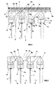
- the suction box of the invention generally indicated with reference numeral 1
- a paper making machine of which also in Fig. 1 a part of the filtering surface 2 can be seen, on whose upper side 2a the film to be dried indicated with reference numeral 3 and containing the suspended cellulose fibers is spread.
- the suction box 1 comprises a plurality of substantially vertical ducts generally indicated with reference numeral 4, provided with openings generally indicated with A, directed to the lower side 2b of the filtering surface 2 and arranged transversally thereto.
- said ducts 4 comprise a plurality of first ducts 5 with first openings 5a for feeding a heating fluid against said filtering surface 2 and a plurality of second ducts 6 with corresponding second openings 6a for the suction operation at said filtering surface 2, each of said first ducts 5 being coupled to a corresponding second duct 6 so as to arrange each first opening 5a adjacent to a corresponding second opening 6a.
- each first opening 5a has a sectional shape 5b diverging to the filtering surface 2 and each second opening 6a on the contrary has a sectional shape 6b convergent to said filtering surface 2.
- the first ducts 5 and the second ducts 6 are coupled to each other so that the end section 5c of the first opening 5a is adjacent and in communication with the start section 6c of the second opening 6a.
- the first 5 and second 6 ducts are defined by a plurality of generally vertical plain walls 7 spaced from one another, having the lower ends 7a bent and joined one after the other so as to create a continuous surface defining the bottom 8 of the suction box 1.
- Each plain wall 7 at the end 7b facing the filtering surface 2 is provided with shaped elements P having a development transversal to the filtering surface 2 to define the shape of said openings A.
- said shaped elements comprise a plurality of symmetrical members 9 with a cross section in the form of an isosceles triangle and a plurality of asymmetrical members 10 with cross section in the form of rectangular trapezium, where each symmetrical shaped member 9 is included between a couple of asymmetrical members 10.
- each first opening 5a is included between the orthogonal side 10a of the cross section in the form of rectangular trapezium of each asymmetrical member 10 and the inclined side 9a of the cross section in the form of isosceles triangle of the corresponding symmetrical member 9.
- each second opening 6a is included between the oblique side 10b of the cross section in the form of rectangular trapezium of each asymmetrical member 10 and the further oblique side 9b of the cross section in the form of isosceles triangle of the corresponding symmetrical member 9.
- Each symmetrical member 9 and each asymmetrical member 10 consists of a shaped bar with longitudinal development 11, 12 respectively, which through a prismatic coupling 15, 16 is coupled to a corresponding support element 13, 14 fixed to the end 7b of each corresponding plain wall 7 defining the ducts 5, 6.
- the prismatic coupling 15, 16 consists of a T shaped male element 11a, 12a belonging to the relevant shaped bar 11, 12, received in a seat 13a, 14a of the corresponding support element 13, 14.
- each first duct 5 in each first duct 5 a hot fluid is being fed, for instance steam, that passing through the first opening 5a with a traveling direction indicated by arrow 17, flows along the lower surface 2b of the filtering surface 2.
- the hot fluid is then sucked according to the traveling direction indicated by arrow 18 through the second opening 6a and along the second duct 6, by the sucking action carried out by a vacuum unit not shown in the drawings and connected to each second duct 6.
- the heating fluid is spread under the filtering surface 2 through the first opening 5a and dries the fluid film 3, so as to evaporate water contained in said film.
- This evaporating effect is integrated by the suction effected by the vacuum unit in each second duct 6, so as to complete drying and removing at the same time the steam.
Landscapes
- Paper (AREA)
- Making Paper Articles (AREA)
Applications Claiming Priority (2)
| Application Number | Priority Date | Filing Date | Title |
|---|---|---|---|
| IT2000VI000115A IT1315354B1 (it) | 2000-05-30 | 2000-05-30 | Cassa aspirante per macchine per la produzione di carta |
| ITVI000115 | 2000-05-30 |
Publications (2)
| Publication Number | Publication Date |
|---|---|
| EP1160376A2 true EP1160376A2 (fr) | 2001-12-05 |
| EP1160376A3 EP1160376A3 (fr) | 2002-05-08 |
Family
ID=11461288
Family Applications (1)
| Application Number | Title | Priority Date | Filing Date |
|---|---|---|---|
| EP01113132A Withdrawn EP1160376A3 (fr) | 2000-05-30 | 2001-05-29 | Caisse aspirante pour machines à papier |
Country Status (2)
| Country | Link |
|---|---|
| EP (1) | EP1160376A3 (fr) |
| IT (1) | IT1315354B1 (fr) |
Cited By (1)
| Publication number | Priority date | Publication date | Assignee | Title |
|---|---|---|---|---|
| CN107130460A (zh) * | 2016-02-29 | 2017-09-05 | 维美德技术有限公司 | 纤维幅材机的脱水装置 |
Family Cites Families (2)
| Publication number | Priority date | Publication date | Assignee | Title |
|---|---|---|---|---|
| US6090243A (en) * | 1989-07-24 | 2000-07-18 | Corbellini; Glauco | Process for preparing a web of paper fibers |
| US5389207A (en) * | 1989-07-24 | 1995-02-14 | Rodriguez; Peter A. | Apparatus for controlling the dewatering of a web in a fourdrinier fabric |
-
2000
- 2000-05-30 IT IT2000VI000115A patent/IT1315354B1/it active
-
2001
- 2001-05-29 EP EP01113132A patent/EP1160376A3/fr not_active Withdrawn
Cited By (1)
| Publication number | Priority date | Publication date | Assignee | Title |
|---|---|---|---|---|
| CN107130460A (zh) * | 2016-02-29 | 2017-09-05 | 维美德技术有限公司 | 纤维幅材机的脱水装置 |
Also Published As
| Publication number | Publication date |
|---|---|
| EP1160376A3 (fr) | 2002-05-08 |
| ITVI20000115A1 (it) | 2001-11-30 |
| ITVI20000115A0 (it) | 2000-05-30 |
| IT1315354B1 (it) | 2003-02-10 |
Similar Documents
| Publication | Publication Date | Title |
|---|---|---|
| ES2197444T3 (es) | Dispositivo estabilizador de lamina de papel continuo. | |
| KR100453213B1 (ko) | 제지기계나 등가물 또는 이들의 피니싱장치에서 먼지를 제거하는 방법 및 장치 | |
| US6148831A (en) | Method for cleaning a web | |
| US4687549A (en) | Hydrofoil blade | |
| JPH04263692A (ja) | 複式すき網形抄紙機の湿部 | |
| US20190078260A1 (en) | Suction device for use in a papermaking machine and a papermaking machine using a suction device | |
| EP1160376A2 (fr) | Caisse aspirante pour machines à papier | |
| CN103781966B (zh) | 用于制造纤维幅的机器的压榨部 | |
| US6562197B2 (en) | Drainage hydrofoil blade | |
| RU98110001A (ru) | Сопловый короб установки для сушки полотна волокнистого материала | |
| US1716866A (en) | Paper strip | |
| FI112268B (fi) | Laite ja menetelmä tissuepaperin valmistamiseksi | |
| US20060283038A1 (en) | Web handling apparatus and process for providing steam to a web material | |
| US5100513A (en) | Defloccing and distribution rolls for papermachine headbox | |
| US6254731B1 (en) | Steam box including a suction zone in an area of a web adjacent to edge cutter devices | |
| FI79729C (fi) | Vattenavledningsanordning. | |
| CN103270215B (zh) | 用于制造材料幅的纸页成形单元以及纸页成形单元的运行方法 | |
| US7686922B2 (en) | Process and device for dewatering a fiber web | |
| EP0241439A2 (fr) | Appareil de dèshydratation | |
| US7504003B2 (en) | Arrangement in a headbox | |
| US20050161186A1 (en) | Papermaking apparatus | |
| EP1245727A1 (fr) | Procédé et dispositif pour la fabrication d' une bande de papier | |
| EP1734179A1 (fr) | Dispositif de séchage d'une bande | |
| CN117604802A (zh) | 斜网成型器 | |
| JPH11279974A (ja) | ヘッドボックス |
Legal Events
| Date | Code | Title | Description |
|---|---|---|---|
| PUAI | Public reference made under article 153(3) epc to a published international application that has entered the european phase |
Free format text: ORIGINAL CODE: 0009012 |
|
| AK | Designated contracting states |
Kind code of ref document: A2 Designated state(s): AT BE CH CY DE DK ES FI FR GB GR IE IT LI LU MC NL PT SE TR |
|
| AX | Request for extension of the european patent |
Free format text: AL;LT;LV;MK;RO;SI |
|
| PUAL | Search report despatched |
Free format text: ORIGINAL CODE: 0009013 |
|
| AK | Designated contracting states |
Kind code of ref document: A3 Designated state(s): AT BE CH CY DE DK ES FI FR GB GR IE IT LI LU MC NL PT SE TR |
|
| AX | Request for extension of the european patent |
Free format text: AL;LT;LV;MK;RO;SI |
|
| AKX | Designation fees paid | ||
| REG | Reference to a national code |
Ref country code: DE Ref legal event code: 8566 |
|
| STAA | Information on the status of an ep patent application or granted ep patent |
Free format text: STATUS: THE APPLICATION HAS BEEN WITHDRAWN |
|
| 18W | Application withdrawn |
Effective date: 20030414 |