EP1160508A2 - Lampe - Google Patents
Lampe Download PDFInfo
- Publication number
- EP1160508A2 EP1160508A2 EP01108408A EP01108408A EP1160508A2 EP 1160508 A2 EP1160508 A2 EP 1160508A2 EP 01108408 A EP01108408 A EP 01108408A EP 01108408 A EP01108408 A EP 01108408A EP 1160508 A2 EP1160508 A2 EP 1160508A2
- Authority
- EP
- European Patent Office
- Prior art keywords
- luminaire according
- links
- support arm
- base
- bending element
- Prior art date
- Legal status (The legal status is an assumption and is not a legal conclusion. Google has not performed a legal analysis and makes no representation as to the accuracy of the status listed.)
- Granted
Links
- 238000005452 bending Methods 0.000 claims description 51
- 239000000463 material Substances 0.000 claims description 9
- 239000004417 polycarbonate Substances 0.000 claims description 7
- 229920000515 polycarbonate Polymers 0.000 claims description 4
- 230000002349 favourable effect Effects 0.000 claims description 3
- 239000011347 resin Substances 0.000 claims description 3
- 229920005989 resin Polymers 0.000 claims description 3
- 239000004033 plastic Substances 0.000 claims description 2
- 229910000831 Steel Inorganic materials 0.000 description 2
- 230000003287 optical effect Effects 0.000 description 2
- 229920006324 polyoxymethylene Polymers 0.000 description 2
- 239000010959 steel Substances 0.000 description 2
- 229920005176 Hostaform® Polymers 0.000 description 1
- 239000004425 Makrolon Substances 0.000 description 1
- 241000270295 Serpentes Species 0.000 description 1
- 229910000639 Spring steel Inorganic materials 0.000 description 1
- 229920005027 Ultraform® Polymers 0.000 description 1
- 230000015572 biosynthetic process Effects 0.000 description 1
- 239000002131 composite material Substances 0.000 description 1
- 239000004020 conductor Substances 0.000 description 1
- 230000001627 detrimental effect Effects 0.000 description 1
- 230000000694 effects Effects 0.000 description 1
- 238000005286 illumination Methods 0.000 description 1
- 238000004519 manufacturing process Methods 0.000 description 1
- NJPPVKZQTLUDBO-UHFFFAOYSA-N novaluron Chemical compound C1=C(Cl)C(OC(F)(F)C(OC(F)(F)F)F)=CC=C1NC(=O)NC(=O)C1=C(F)C=CC=C1F NJPPVKZQTLUDBO-UHFFFAOYSA-N 0.000 description 1
- 238000007493 shaping process Methods 0.000 description 1
- 238000002834 transmittance Methods 0.000 description 1
- 230000000007 visual effect Effects 0.000 description 1
Images


Classifications
-
- F—MECHANICAL ENGINEERING; LIGHTING; HEATING; WEAPONS; BLASTING
- F21—LIGHTING
- F21V—FUNCTIONAL FEATURES OR DETAILS OF LIGHTING DEVICES OR SYSTEMS THEREOF; STRUCTURAL COMBINATIONS OF LIGHTING DEVICES WITH OTHER ARTICLES, NOT OTHERWISE PROVIDED FOR
- F21V21/00—Supporting, suspending, or attaching arrangements for lighting devices; Hand grips
- F21V21/14—Adjustable mountings
- F21V21/32—Flexible tubes
Definitions
- the invention relates to a lamp with a lamp body and a support arm that carries the lamp body at one end and at the opposite end for connection to a base part is set up, the support arm a continuous Includes a series of links using joints are interconnected
- Such lights are known (DE 295 11 851 U1; DE 87 07 756 U1; EP-A 0 353 220).
- the weight of the support arm is particularly strong the connecting joints in the area of the support arm near the base.
- the sliding surfaces of the Connecting joints have a sufficiently high friction, which is not always achievable in practice.
- the object of the present invention is to provide a lamp to improve the type mentioned so that an undesirable Bending of the support arm, especially in the area near the base due to insufficient load capacities is avoided.
- the invention provides that the support arm at least an extending over the connecting joints near the base, arranged essentially inside the limbs Bending element that the use of the lamp by Bending at least part of the connection joints close to the base acting torques.
- the lamp body is the part of the lamp that is used for Includes the lamp.
- the base part of the lamp is used to support or to attach the lamp, for example a table or a wall; it can be, for example Stand, a clamp holder or a wall holder.
- the part connecting the base part to the lamp body the lamp is called a support arm. With the help of the support arm the lamp body is carried freely in the room.
- a continuous series of links means that continuous one link to the next.
- the limbs are therefore connected in series; however, it is not required that this applies to all links of the support arm.
- For the A single link usually has two in series mutually opposite connection points. On this Joints are the links with the help of connecting joints connected with each other.
- the bending element has the property that one on the Element applied bending moment a corresponding bending resistance opposed. It extends according to the invention at least above the base (adjacent to the base) Part of the support arm, preferably at least over 20%, further preferably at least 30%, more preferably at least 40% of the support arm length and / or preferably over at least three, more preferably at least five, more preferably at least seven support arm links close to the base.
- the bending element can preferably extend over the entire support arm.
- a part of the Support arm extending bending element can also be a plurality such elements may be provided; they extend then in its entirety over the part of the support arm near the base.
- a connecting joint between two neighboring ones limbs close to the base over the connecting joint extending and a piece into the corresponding links protruding bending element it is only necessary that a connecting joint between two neighboring ones limbs close to the base over the connecting joint extending and a piece into the corresponding links protruding bending element.
- the following is mostly formulated in relation to a single bending element, can, however, analogously to one of a plurality of bending elements composite bending element are transmitted.
- the arrangement of the bending element inside the links is off advantageous for optical reasons. It is understood that the bending element especially at the joints of the limbs can run outside the same.
- the torque acting on the connecting joints near the base is determined by the weight of the lamp body and the generated part of the support arm remote from the base.
- the property of the bending element, at least when using the lamp a part of the acting on the connecting joints near the base Picking up torque refers to the ordinary one Use of the lamp.
- the flexure is not required absorb a bending moment under all conceivable circumstances got to. E.g. the lamp can possibly be in an elongated Form in which the bending element is no Torque. It is also not necessary that the Bending element in the use of the lamp over the entire base near the base Part of the arm receives torque, although this is advantageously the case.
- the property of the bending element delimits the flexure from the power line wires or power cables of the lights of the prior art (G 87 07 756.6) from. These may be flexible, but can no torques to an extent relevant to the invention take up.
- the connecting joints are made by the bending element according to the invention the links in the area of the support arm near the base relieved, since at least part of the corresponding Connecting torques acting torques from the bending element by bending the same.
- the invention has recognized that only with the help of friction in the connecting joints often not sufficiently stable Luminaire is guaranteed in the desired position, in particular with large extension widths of the support arm. Without the invention Bending element there is a risk that the The lamp sags in a connection joint near the base. Also the wear of the connecting joints is due to the invention reduced.
- the bending element is at least in use of the lamp 30% of those acting on the corresponding connecting joints Absorbs torques.
- the bending element preferably takes at least 50% of these torques.
- the rest Part of the torques can be, for example, by friction or Detent, are picked up by the joints near the base.
- the bending element is preferably over the entire adjustment range of the support arm is flexible. It then practices opposite the bending according to the invention an elastic restoring force out. Bending-elastic elements generally have one less wear than plastically bendable bending elements. However, these are also encompassed by the invention.
- the bending element here preferably over the rest Part reinforced. This can be done, for example, in the form that the bending element is double-layered in the area near the base is.
- bending element to conduct current from the base part to Luminaire body can be on separate Supply lines are dispensed with. Then are expedient two flexural elastic elements isolated from each other for formation a circuit provided.
- bushings and / or recesses in the one Joint elements forming joint are provided, in which the bending element or the power lines are guided are.
- the bushings / recesses run expediently approximately parallel to the support arm axis.
- a swivel, for example. is formed by a joint bearing part and a joint shaft part.
- at least the articulated shaft part a closed implementation.
- the invention is particularly useful for such materials for the limbs and / or joints that are fragile because they absorb only limited forces can.
- the limbs can be essentially translucent Plastic, preferably polycarbonate PC according to DIN 7744, ISO 7391 exist.
- Translucent means a light transmittance according to DIN 5036-1 of at least 60%, preferably at least 80% at 1 mm thickness.
- a preferred one The material is Makrolon. Since the friction, for example, from PC to PC is disadvantageous, is preferred - this characteristic is possibly worthy of independent protection - at least one of the sliding surfaces a joint of a material with a more favorable sliding and / or wear behavior formed.
- Preferred materials are, for example, Hostaform or Ultraform.
- connection joint between two neighboring ones Limbs executed with a click This means that the two links relative to each other in at least two discrete ones Positions are stable.
- through the detent is a part of the on the connecting joints near the base Torque acting range and thus reduces the stress on the corresponding joints.
- the position of the links relative to each other established what a more uniform appearance contributes.
- a locking joint in forming the two joint sliding surfaces in a profiled manner.
- a swivel joint can be polygonal profiling the shaft part and the cooperating bearing part act.
- the pivoting range of a link is preferably relative to an adjacent link on one or both sides by one or two stops limited, preferably such that the Center axes an angle of at most 40 °, preferably include at most 30 °, more preferably at most 20 °. In this way, the appearance of severe curvatures avoided what can be detrimental to the visual impression.
- the support arm preferably consists of a plurality, preferably at least 5, more preferably at least 10, further preferably at least 15 links. It becomes an individual Shaping the support arm, for example, in the form of a snake. For a uniform aesthetic effect, it is advantageous if essentially all the links are of the same design are. It is understood that this is not for everyone Links must apply, for example for a connecting link on the base and / or on the lamp body.
- first joint element e.g. shaft part
- second joint element e.g. bearing part
- two adjacent links are each by one Swivel joint connected, its axis of rotation perpendicular to the central axes both limbs run.
- the support arm can then only be adjusted on one level and not, for example, be pivoted sideways, resulting in a inconsistent appearance. To that extent this embodiment is advantageous over the use of ball joints.
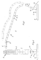
- the lamp 1 rests on a base part designed as a pedestal 8, which is connected to the support arm 2.
- the free end of the support arm 2 carries the lamp body 5, the lamp records.
- the support arm 2 is a chain of seventeen identically trained members 3 formed with the help of Connecting joints 4 are interconnected.
- the support arm 2 On his end near the base, the support arm 2 has a base member 7, set up for inserting the connecting cable 10 into the lamp 1 is and a switch 11 for switching on and off of the lamp.
- a clamp holder 26 (FIG. 11) or a wall holder 27 (FIG. 12) may be provided.
- the links 3 are hollow-chambered, they are made of walls 28 and inner stiffening walls 30 are formed.
- a single one Support arm link 3 is made of two pieces Limb halves 29 formed. Two to be combined into a link 3 Halves 29 are substantially symmetrical in relation trained on the support arm level. This is the vertical one Middle plane, which the support arm in every possible position includes.
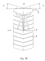
- the limbs are 36 with the help of locking webs clipped together and / or glued together. In cross section perpendicular to the support arm axis results for a support arm link 3 of the visible in Fig. 10 for the lamp body 5 Cross-section.
- the support arm axis denotes the middle one Longitudinal axis of the support arm. It is section by section of corresponding Center axes 15 of the support arm members 3 are formed.
- first connection side 12 of the links 3 there are articulated bushings 13 arranged, the the spherical bearing parts of a Form joint.
- On the opposite Side is a receptacle 37 with a hexagon opening 38 arranged.
- a pivot pin is inserted into the receptacle 37 40 with a corresponding hexagonal extension 39 rotatably used.
- the two joint bushings 13, each one of the Link halves 29 are associated with their end faces to each other and in this way form a continuous Spherical bearing for the pivot pin 40 of the neighboring one Support arm link 3, the drive shaft of the thus formed Pivot bearing 4 forms.
- Two adjacent links 3 can around corresponding, in Fig.
- a link 3 is formed from only three parts, namely two halves 29 and the pivot pin 40. the number of different Parts is therefore very small.
- the links 3 are on their connecting sides 12 and 17, respectively wedge-shaped, with each facing preferably wedge tips almost touching each other.
- the wedge shape results in the central cross section of a link 3 perpendicular to the corresponding swivel axis.
- the corresponding Wedge surfaces 21, 22 form an angle of 18 ° each one perpendicular to the central axis 15 and the pivot axis 23 Transverse axis.
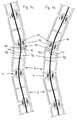
- the wedge surfaces 21, 22 form stop surfaces, which the swivel range of two adjacent links 3 to each other limit, as is apparent from Figures 5a and 5c. In these outer pivot positions each have two neighboring ones Wedge surfaces 21, 22 flat against each other, what the Pressure load on the walls forming the wedge surfaces 21, 22 28 reduced. Because of these stops, two can go together neighboring links 3 each by 18 ° relative to the central position, in which the central axes 15 of both links together be cursed, swiveled.
- the bearing bush 13 and the receiving bush 37 are in one piece formed with the link half 29 to the manufacturing cost and reduce the number of parts.
- the limb halves 29 exist made of translucent polycarbonate PC that different can be colored.
- the pivot pin 40 is made of polyacetyl resin POM. The favorable sliding properties of this material lead to reduced joint wear.
- the hinge pin 40 has a polygonal profile on its outer circumference 35 on. It is a regular one Zwanzigeck, so that adjacent profile surfaces each form an angle of 18 °.
- the spherical bearing bushes 13 have a corresponding on their inner circumference Polygonal profiling 33.
- the two profiles 33, 35 form a detent; two adjacent links 3 are in different swivel positions in steps of each held at 18 °, as shown in FIGS. 5a-5c can be seen.
- the stop surfaces 21, 22 ensure as above explained that in the present case exactly three locking positions exist, namely the straight middle position (Fig. 5b), in which the central axes of the links 3 with each other align, and the two outer locking positions (Fig. 5a, 5c), in which the central axes each have an angle of 18 ° include with each other.
- FIG. 1 A further embodiment is shown in FIG which the detent from webs 24 of the spherical bearing parts 13 and grooves 25 of the propeller shaft parts 18 is formed (grooving).
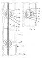
- the bushing 44 has a relatively large volume of the pivot pin 40 takes, it is for the stability of the joint pin 40 advantageous if this is formed in one piece and not in two parts, as is the case, for example, with the spherical bearing bushes 13 Case is.
- the passage 44 in the articulated shaft part 40 is preferred closed in the manner of a hole, so the bending element 42 or the power lines enclosed on all sides and are kept.
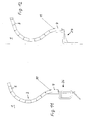
- the spring band steels 42 are over the entire adjustment range of the support arm 2 flexible.
- Links 3 next to the base are the bending elements 42 each performed twice (not shown in the figures) and on this Way amplified. If there are two adjacent links 3 in one to each other, this leads to a bending of the bending elements 42 (see FIGS. 7b, 7c) and this relieves the pressure on the joint joint 4, since the bending element 42 due to the bending one Absorbs part of the forces acting on the connecting joint 4.
- the bending elements strike 42 at the ends 45 forming the recesses 16 of the spherical bearing bushes 13, which are rounded off for this purpose are.
- the sockets 13 are on their facing away from the respective link 3 Page 46 more trained, since here the largest Loads occur.
- the two bending elements 42 are called mutually insulated conductors from the base part 8 used for the lamp body 5.
- the lamp body 5 is by means of a rod-shaped control element 9 about its central axis by 18 ° swiveling to both sides, also to a certain side To enable adjustability of the light illumination.
Landscapes
- Engineering & Computer Science (AREA)
- General Engineering & Computer Science (AREA)
- Non-Portable Lighting Devices Or Systems Thereof (AREA)
- Fastening Of Light Sources Or Lamp Holders (AREA)
- Endoscopes (AREA)
- Arrangements Of Lighting Devices For Vehicle Interiors, Mounting And Supporting Thereof, Circuits Therefore (AREA)
- Pivots And Pivotal Connections (AREA)
- Vessels And Coating Films For Discharge Lamps (AREA)
Applications Claiming Priority (2)
| Application Number | Priority Date | Filing Date | Title |
|---|---|---|---|
| DE20009799U DE20009799U1 (de) | 2000-05-31 | 2000-05-31 | Leuchte |
| DE20009799U | 2000-05-31 |
Publications (3)
| Publication Number | Publication Date |
|---|---|
| EP1160508A2 true EP1160508A2 (fr) | 2001-12-05 |
| EP1160508A3 EP1160508A3 (fr) | 2004-07-14 |
| EP1160508B1 EP1160508B1 (fr) | 2008-07-16 |
Family
ID=7942288
Family Applications (1)
| Application Number | Title | Priority Date | Filing Date |
|---|---|---|---|
| EP01108408A Expired - Lifetime EP1160508B1 (fr) | 2000-05-31 | 2001-04-03 | Lampe |
Country Status (3)
| Country | Link |
|---|---|
| EP (1) | EP1160508B1 (fr) |
| AT (1) | ATE401531T1 (fr) |
| DE (2) | DE20009799U1 (fr) |
Cited By (3)
| Publication number | Priority date | Publication date | Assignee | Title |
|---|---|---|---|---|
| WO2005028943A1 (fr) * | 2003-09-19 | 2005-03-31 | Joergensen Niels S | Dispositif reglable comprenant deux ou plusieurs elements interconnectes, ces elements formant de preference une chaine oblongue |
| EP1612470A3 (fr) * | 2004-06-15 | 2006-08-16 | Simona Maiolino | Lampe linéaire articulée |
| WO2012001505A3 (fr) * | 2010-07-01 | 2012-03-15 | Benocci, Sergio | Lampe |
Families Citing this family (1)
| Publication number | Priority date | Publication date | Assignee | Title |
|---|---|---|---|---|
| DE202014011147U1 (de) * | 2014-10-16 | 2018-02-16 | "Durable" Hunke & Jochheim Gmbh & Co. Kommanditgesellschaft | Beleuchtungssystem |
Citations (3)
| Publication number | Priority date | Publication date | Assignee | Title |
|---|---|---|---|---|
| DE8707756U1 (de) | 1987-05-30 | 1987-08-20 | Schladitz, Klaus, 8201 Prutting | Niederspannungsschiene mit aufsteckbarem Strahler |
| EP0353220A2 (fr) | 1988-07-27 | 1990-01-31 | Karin Pesau | Lampe électrique |
| DE29511851U1 (de) | 1994-08-05 | 1995-11-09 | Black & Decker Inc | Handleuchte |
Family Cites Families (6)
| Publication number | Priority date | Publication date | Assignee | Title |
|---|---|---|---|---|
| US1279803A (en) * | 1917-09-29 | 1918-09-24 | George F Watson | Light-support. |
| GB460441A (en) * | 1935-07-25 | 1937-01-25 | Harold Cyril Cooper | Improvements in or relating to articulated joints |
| EP0381909A1 (fr) * | 1988-10-18 | 1990-08-16 | Associate Designers, S.A. | Bras de support |
| DE9010337U1 (de) * | 1990-07-09 | 1990-09-13 | Chin-Song, Chen, Taipeh/T'ai-pei | Tischlampe |
| WO1994009314A1 (fr) * | 1992-10-17 | 1994-04-28 | Pius Ponticelli | Composant pour fabriquer un objet utilitaire flexible |
| US6042245A (en) * | 1998-04-02 | 2000-03-28 | Stanley; Terry D. | Switch attachment |
-
2000
- 2000-05-31 DE DE20009799U patent/DE20009799U1/de not_active Expired - Lifetime
-
2001
- 2001-04-03 AT AT01108408T patent/ATE401531T1/de not_active IP Right Cessation
- 2001-04-03 EP EP01108408A patent/EP1160508B1/fr not_active Expired - Lifetime
- 2001-04-03 DE DE50114110T patent/DE50114110D1/de not_active Expired - Fee Related
Patent Citations (3)
| Publication number | Priority date | Publication date | Assignee | Title |
|---|---|---|---|---|
| DE8707756U1 (de) | 1987-05-30 | 1987-08-20 | Schladitz, Klaus, 8201 Prutting | Niederspannungsschiene mit aufsteckbarem Strahler |
| EP0353220A2 (fr) | 1988-07-27 | 1990-01-31 | Karin Pesau | Lampe électrique |
| DE29511851U1 (de) | 1994-08-05 | 1995-11-09 | Black & Decker Inc | Handleuchte |
Cited By (3)
| Publication number | Priority date | Publication date | Assignee | Title |
|---|---|---|---|---|
| WO2005028943A1 (fr) * | 2003-09-19 | 2005-03-31 | Joergensen Niels S | Dispositif reglable comprenant deux ou plusieurs elements interconnectes, ces elements formant de preference une chaine oblongue |
| EP1612470A3 (fr) * | 2004-06-15 | 2006-08-16 | Simona Maiolino | Lampe linéaire articulée |
| WO2012001505A3 (fr) * | 2010-07-01 | 2012-03-15 | Benocci, Sergio | Lampe |
Also Published As
| Publication number | Publication date |
|---|---|
| DE20009799U1 (de) | 2001-12-06 |
| ATE401531T1 (de) | 2008-08-15 |
| DE50114110D1 (de) | 2008-08-28 |
| EP1160508A3 (fr) | 2004-07-14 |
| EP1160508B1 (fr) | 2008-07-16 |
Similar Documents
| Publication | Publication Date | Title |
|---|---|---|
| EP1200753B1 (fr) | Chaine articulee pour cables d'alimentation | |
| DE69713297T2 (de) | Scharnier mit elastisch überdehnbarem offenanschlag sowie eine ein derartiges scharnier umfassende brille | |
| EP1844204A2 (fr) | Charniere a articulations multiples | |
| EP1948893B1 (fr) | Dispositif de levage pour un volet pliant à deux battants | |
| EP0626604A2 (fr) | Tube endoscopique flexible | |
| AT403503B (de) | Verbindungsbeschlag | |
| AT12372U1 (de) | Vollkommen versenkbares, verbessertes scharnier mit positionseinstellung für türen und/oder möbeltüren | |
| DE60213570T2 (de) | Vorrichtung zur halterung und justierung eines bauteils | |
| AT392320B (de) | Weitwinkelscharnier | |
| EP0356761A1 (fr) | Dispositif de levage à ciseaux, en particulier pour une plate-forme de travail | |
| EP3649356A1 (fr) | Articulation | |
| EP1160508B1 (fr) | Lampe | |
| WO1990015911A1 (fr) | Charniere | |
| DE202015102263U1 (de) | 180°-Scharnier | |
| DE8801248U1 (de) | Schere, insbesondere Friseurschere | |
| EP1827770B1 (fr) | Cisaille, en particulier taille-haie | |
| EP1143194A1 (fr) | Lampadaire | |
| EP0875648B1 (fr) | Charnière à grand angle d'ouverture | |
| DE3916123C2 (fr) | ||
| DE19856684A1 (de) | Gelenk | |
| DE29803998U1 (de) | Zange | |
| DE69402598T2 (de) | Präsentationsecktheke | |
| EP1267011A1 (fr) | Store à bras articulés avec ressort | |
| DE102010034185B3 (de) | Zirkel | |
| DE102008048769B4 (de) | Türband für eine Pendel- oder Schwenktür |
Legal Events
| Date | Code | Title | Description |
|---|---|---|---|
| PUAI | Public reference made under article 153(3) epc to a published international application that has entered the european phase |
Free format text: ORIGINAL CODE: 0009012 |
|
| AK | Designated contracting states |
Kind code of ref document: A2 Designated state(s): AT BE CH CY DE DK ES FI FR GB GR IE IT LI LU MC NL PT SE TR |
|
| AX | Request for extension of the european patent |
Free format text: AL;LT;LV;MK;RO;SI |
|
| PUAL | Search report despatched |
Free format text: ORIGINAL CODE: 0009013 |
|
| AK | Designated contracting states |
Kind code of ref document: A3 Designated state(s): AT BE CH CY DE DK ES FI FR GB GR IE IT LI LU MC NL PT SE TR |
|
| AX | Request for extension of the european patent |
Extension state: AL LT LV MK RO SI |
|
| 17P | Request for examination filed |
Effective date: 20041209 |
|
| AKX | Designation fees paid |
Designated state(s): AT BE CH CY DE DK ES FI FR GB GR IE IT LI LU MC NL PT SE TR |
|
| GRAP | Despatch of communication of intention to grant a patent |
Free format text: ORIGINAL CODE: EPIDOSNIGR1 |
|
| GRAS | Grant fee paid |
Free format text: ORIGINAL CODE: EPIDOSNIGR3 |
|
| GRAA | (expected) grant |
Free format text: ORIGINAL CODE: 0009210 |
|
| AK | Designated contracting states |
Kind code of ref document: B1 Designated state(s): AT BE CH CY DE DK ES FI FR GB GR IE IT LI LU MC NL PT SE TR |
|
| REG | Reference to a national code |
Ref country code: GB Ref legal event code: FG4D Free format text: NOT ENGLISH |
|
| REG | Reference to a national code |
Ref country code: CH Ref legal event code: EP |
|
| REF | Corresponds to: |
Ref document number: 50114110 Country of ref document: DE Date of ref document: 20080828 Kind code of ref document: P |
|
| REG | Reference to a national code |
Ref country code: IE Ref legal event code: FG4D Free format text: LANGUAGE OF EP DOCUMENT: GERMAN |
|
| NLV1 | Nl: lapsed or annulled due to failure to fulfill the requirements of art. 29p and 29m of the patents act | ||
| PG25 | Lapsed in a contracting state [announced via postgrant information from national office to epo] |
Ref country code: PT Free format text: LAPSE BECAUSE OF FAILURE TO SUBMIT A TRANSLATION OF THE DESCRIPTION OR TO PAY THE FEE WITHIN THE PRESCRIBED TIME-LIMIT Effective date: 20081216 Ref country code: NL Free format text: LAPSE BECAUSE OF FAILURE TO SUBMIT A TRANSLATION OF THE DESCRIPTION OR TO PAY THE FEE WITHIN THE PRESCRIBED TIME-LIMIT Effective date: 20080716 Ref country code: ES Free format text: LAPSE BECAUSE OF FAILURE TO SUBMIT A TRANSLATION OF THE DESCRIPTION OR TO PAY THE FEE WITHIN THE PRESCRIBED TIME-LIMIT Effective date: 20081027 |
|
| PG25 | Lapsed in a contracting state [announced via postgrant information from national office to epo] |
Ref country code: FI Free format text: LAPSE BECAUSE OF FAILURE TO SUBMIT A TRANSLATION OF THE DESCRIPTION OR TO PAY THE FEE WITHIN THE PRESCRIBED TIME-LIMIT Effective date: 20080716 |
|
| REG | Reference to a national code |
Ref country code: IE Ref legal event code: FD4D |
|
| PG25 | Lapsed in a contracting state [announced via postgrant information from national office to epo] |
Ref country code: IE Free format text: LAPSE BECAUSE OF FAILURE TO SUBMIT A TRANSLATION OF THE DESCRIPTION OR TO PAY THE FEE WITHIN THE PRESCRIBED TIME-LIMIT Effective date: 20080716 Ref country code: DK Free format text: LAPSE BECAUSE OF FAILURE TO SUBMIT A TRANSLATION OF THE DESCRIPTION OR TO PAY THE FEE WITHIN THE PRESCRIBED TIME-LIMIT Effective date: 20080716 |
|
| PLBE | No opposition filed within time limit |
Free format text: ORIGINAL CODE: 0009261 |
|
| STAA | Information on the status of an ep patent application or granted ep patent |
Free format text: STATUS: NO OPPOSITION FILED WITHIN TIME LIMIT |
|
| 26N | No opposition filed |
Effective date: 20090417 |
|
| PG25 | Lapsed in a contracting state [announced via postgrant information from national office to epo] |
Ref country code: IT Free format text: LAPSE BECAUSE OF FAILURE TO SUBMIT A TRANSLATION OF THE DESCRIPTION OR TO PAY THE FEE WITHIN THE PRESCRIBED TIME-LIMIT Effective date: 20080716 |
|
| BERE | Be: lapsed |
Owner name: TOBIAS GRAU Effective date: 20090430 |
|
| PGFP | Annual fee paid to national office [announced via postgrant information from national office to epo] |
Ref country code: DE Payment date: 20090624 Year of fee payment: 9 |
|
| REG | Reference to a national code |
Ref country code: CH Ref legal event code: PL |
|
| GBPC | Gb: european patent ceased through non-payment of renewal fee |
Effective date: 20090403 |
|
| REG | Reference to a national code |
Ref country code: FR Ref legal event code: ST Effective date: 20091231 |
|
| PG25 | Lapsed in a contracting state [announced via postgrant information from national office to epo] |
Ref country code: CH Free format text: LAPSE BECAUSE OF NON-PAYMENT OF DUE FEES Effective date: 20090430 Ref country code: SE Free format text: LAPSE BECAUSE OF FAILURE TO SUBMIT A TRANSLATION OF THE DESCRIPTION OR TO PAY THE FEE WITHIN THE PRESCRIBED TIME-LIMIT Effective date: 20081016 Ref country code: LI Free format text: LAPSE BECAUSE OF NON-PAYMENT OF DUE FEES Effective date: 20090430 |
|
| PG25 | Lapsed in a contracting state [announced via postgrant information from national office to epo] |
Ref country code: FR Free format text: LAPSE BECAUSE OF NON-PAYMENT OF DUE FEES Effective date: 20091222 Ref country code: MC Free format text: LAPSE BECAUSE OF NON-PAYMENT OF DUE FEES Effective date: 20090430 Ref country code: GB Free format text: LAPSE BECAUSE OF NON-PAYMENT OF DUE FEES Effective date: 20090403 |
|
| PG25 | Lapsed in a contracting state [announced via postgrant information from national office to epo] |
Ref country code: BE Free format text: LAPSE BECAUSE OF NON-PAYMENT OF DUE FEES Effective date: 20090430 |
|
| PG25 | Lapsed in a contracting state [announced via postgrant information from national office to epo] |
Ref country code: AT Free format text: LAPSE BECAUSE OF NON-PAYMENT OF DUE FEES Effective date: 20090403 |
|
| PG25 | Lapsed in a contracting state [announced via postgrant information from national office to epo] |
Ref country code: GR Free format text: LAPSE BECAUSE OF FAILURE TO SUBMIT A TRANSLATION OF THE DESCRIPTION OR TO PAY THE FEE WITHIN THE PRESCRIBED TIME-LIMIT Effective date: 20081017 |
|
| PG25 | Lapsed in a contracting state [announced via postgrant information from national office to epo] |
Ref country code: DE Free format text: LAPSE BECAUSE OF NON-PAYMENT OF DUE FEES Effective date: 20101103 |
|
| PG25 | Lapsed in a contracting state [announced via postgrant information from national office to epo] |
Ref country code: LU Free format text: LAPSE BECAUSE OF NON-PAYMENT OF DUE FEES Effective date: 20090403 |
|
| PG25 | Lapsed in a contracting state [announced via postgrant information from national office to epo] |
Ref country code: TR Free format text: LAPSE BECAUSE OF FAILURE TO SUBMIT A TRANSLATION OF THE DESCRIPTION OR TO PAY THE FEE WITHIN THE PRESCRIBED TIME-LIMIT Effective date: 20080716 |
|
| PG25 | Lapsed in a contracting state [announced via postgrant information from national office to epo] |
Ref country code: CY Free format text: LAPSE BECAUSE OF FAILURE TO SUBMIT A TRANSLATION OF THE DESCRIPTION OR TO PAY THE FEE WITHIN THE PRESCRIBED TIME-LIMIT Effective date: 20080716 |