EP1160508B1 - Lampe - Google Patents
Lampe Download PDFInfo
- Publication number
- EP1160508B1 EP1160508B1 EP01108408A EP01108408A EP1160508B1 EP 1160508 B1 EP1160508 B1 EP 1160508B1 EP 01108408 A EP01108408 A EP 01108408A EP 01108408 A EP01108408 A EP 01108408A EP 1160508 B1 EP1160508 B1 EP 1160508B1
- Authority
- EP
- European Patent Office
- Prior art keywords
- lamp according
- members
- lamp
- support arm
- joint
- Prior art date
- Legal status (The legal status is an assumption and is not a legal conclusion. Google has not performed a legal analysis and makes no representation as to the accuracy of the status listed.)
- Expired - Lifetime
Links
Images




Classifications
-
- F—MECHANICAL ENGINEERING; LIGHTING; HEATING; WEAPONS; BLASTING
- F21—LIGHTING
- F21V—FUNCTIONAL FEATURES OR DETAILS OF LIGHTING DEVICES OR SYSTEMS THEREOF; STRUCTURAL COMBINATIONS OF LIGHTING DEVICES WITH OTHER ARTICLES, NOT OTHERWISE PROVIDED FOR
- F21V21/00—Supporting, suspending, or attaching arrangements for lighting devices; Hand grips
- F21V21/14—Adjustable mountings
- F21V21/32—Flexible tubes
Definitions
- the invention relates to a lamp according to claim 1, comprising a lamp body and a support arm which carries at one end the lamp body and is arranged at the opposite end for connection to a Sokkelteil, wherein the support arm comprises a continuous series of links, which by means of Connecting joints are connected to each other,
- Object of the present invention is to improve a lamp of the type mentioned so that an undesirable bending of the support arm is avoided in particular in the area near the base due to insufficient carrying capacity.
- the support arm has at least one over the sockelnahen connection joints extending, arranged substantially in the interior of the members bending element, which in the use of the lamp by bending at least a portion of the sockelnahen connection joints absorbs acting torques.
- the luminaire body is that part of the luminaire which serves to receive the luminous means.
- the base part of the lamp is used for supporting or fixing the lamp eg. At a table or wall; it may, for example, be a base, a clamp holder or a wall holder.
- the part of the luminaire connecting the base part to the luminaire body is referred to as a support arm. With the help of the support arm, the lamp body is carried freely in the room.
- a continuous series of links means that one link is consecutively lined up to the next.
- the links are therefore connected in series; however, it is not required that this be true for all members of the support arm.
- a single member usually has two opposite connection points. At these joints, the links are connected by means of connecting joints.
- the bending element has the property that it opposes a corresponding bending resistance to a bending moment exerted on the element. According to the invention, it extends at least over the portion of the support arm close to the base (adjacent to the base), preferably at least more than 20%, more preferably at least 30%, further preferably at least 40% of the support arm length and / or preferably at least three, more preferably at least five, more preferably at least seven pedestal near support arm members.
- the flexure may preferably extend over the entire support arm.
- a bending element extending over the entire base part of the support arm
- a plurality of such elements may also be provided; they then extend in their entirety over the base near the base of the support arm.
- a connecting joint between two adjacent sockelnahen members has a extending over the connecting joint and a piece projecting into the corresponding members bending element.
- the following is usually formulated with respect to a single flexure, but may be analogously applied to a flexure composed of a plurality of flexures.
- the arrangement of the bending element in the interior of the links is advantageous for optical reasons. It is understood that the bending element can extend, in particular at the connection points of the links outside the same.
- the torque acting on the socket-near connection joints is generated by the weight of the lamp body and the remaining part of the support arm remote from the socket.
- the property of the bending element, in the use of the lamp to accommodate at least a portion of the torques acting on the socket-like connecting joints torques refers to the ordinary use of the lamp. It is not required that the bending element must absorb a bending moment under all conceivable circumstances. For example. If necessary, the light can be brought into an elongated form in which the bending element does not absorb any torque. It is also not necessary that the bending element in the use of the lamp over the entire sokkelnahen Part of the support arm receives a torque, although this is advantageously the case.
- the bending element separates from the power line wires or power cables of the lights of the prior art (G 87 07 756.6). These may be bendable, but can not absorb torques in a relevant scope according to the invention.
- the connecting joints of the links in the area near the base of the support arm are relieved, since at least some of the torques acting on the corresponding connecting joints are absorbed by the bending element by bending it.
- the arrangement takes into account at least in the vicinity of the pedestal near the support arm, that here act the largest torques.
- the invention has recognized that often alone with the help of friction in the connecting joints no sufficiently stable holding the lamp is guaranteed in the desired position, especially with large deployment widths of the support arm. Without the bending element according to the invention there is a risk that the lamp sags in a socket-joint near joint. The wear of the connecting joints is reduced by the invention.
- the bending element absorbs at least 30% of the torques acting on the corresponding connecting joints during use of the luminaire.
- the bending element absorbs at least 50% of these torques.
- the remaining part of the torques can be absorbed, for example by frictional engagement or by latching, from the socket-near joints.
- the bending element is bending elastic over the entire adjustment range of the support arm. It then exerts an elastic restoring force against the bending according to the invention.
- Bend-elastic elements generally have less wear than plastically bendable bending elements. However, these are also included in the invention.
- the bending element is here preferably reinforced relative to the remaining part. This can happen, for example, in the form that the bending element is double-layered in the area near the base.
- the bending element is used to conduct electricity from the base part to the lamp body, can be dispensed with corresponding separate leads. Conveniently, two mutually insulated flexurally elastic elements are then provided to form a circuit.
- a swivel joint for example, is formed by a joint bearing part and a propeller shaft part.
- the propeller shaft part has a closed passage.
- the invention is particularly useful for such materials, for the links and / or joints that are fragile, as they can only absorb limited forces.
- the members may consist essentially of translucent plastic, preferably polycarbonate PC according to DIN 7744, ISO 7391.
- Translucent means a light transmittance according to DIN 5036-1 of at least 60%, preferably at least 80% at 1 mm thickness.
- a preferred material is Makrolon. Since the friction, for example. From PC to PC is unfavorable, is preferably - this feature is possibly independent worthy of protection - at least one of the sliding surfaces of a connecting joint of a material with a more favorable sliding and / or wear behavior formed.
- This may be, for example, polyacetyl resin POM according to DIN 16781, ISO 9988.
- Preferred materials are, for example, Hostaform or Ultraform.
- the connecting joint between two adjacent links is designed latching.
- the two members are latching relative to each other in at least two discrete positions latching.
- a portion of the torques acting on the connecting joints in the region of the eccentric region is received by the detent, thereby reducing the load on the corresponding joints.
- the position of the links is fixed relative to each other, which contributes to a more uniform appearance.
- curved support arm areas may occur, possibly only a single radius of curvature occurs, which improves the visual impression.
- the central axes of the two members in the two outer detent positions and / or two abutment positions enclose the same angle with each other.
- a particularly simple implementation of a locking joint is formed profiled the two Gelenkgleit vom.
- it may be a polygonal profiling of the shaft part and the bearing part cooperating therewith in a rotary joint.
- the pivotal range of a member relative to an adjacent member is limited on one or both sides by one or two stops, preferably such that the center axes enclose an angle of at most 40 °, preferably at most 30 °, more preferably at most 20 °. In this way, the occurrence of strong bends is avoided, which can be detrimental to the visual impression.
- two adjacent links are wedge-shaped in cross-section at their juncture with wedge tips facing each other.
- the wedge surfaces then form planar stops for the two members, so that, for example, an edge load of the material is avoided. This is particularly advantageous in fracture-sensitive material.
- the support arm of a plurality, preferably at least 5, more preferably at least 10, more preferably at least 15 members.
- This will be an individual Forming of the support arm, for example.
- snake shape allows.
- substantially all members are formed the same. It is understood that this need not apply to all members, for example.
- a connection member on the base and / or the lamp body for a connection member on the base and / or the lamp body.
- the support arm members consist essentially of two integral member halves.
- a first joint element for example shaft part
- a second joint element for example bearing part
- each two adjacent links are connected by a hinge whose axis of rotation is perpendicular to the central axes of both links.
- the support arm can then be adjusted only in one plane and not, for example, be laterally pivoted, which could lead to a non-uniform appearance.
- this embodiment is advantageous over the use of ball joints.
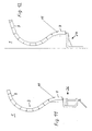
- the lamp 1 rests on a base formed as Sokkelteil 8, which is connected to the support arm 2.
- the free end of the support arm 2 carries the lamp body 5, which receives lighting.
- the support arm 2 is formed by a chain of seventeen equally formed members 3, which are connected to each other by means of connecting joints 4.
- At its base near the end of the support arm 2 has a base member 7, which is adapted to insert the connecting cable 10 in the lamp 1 and has a switch 11 for switching on and off the lamp.
- the base 8 may alternatively be a clamp holder 26 ( Fig. 11 ) or a wall holder 27 (FIG. Fig. 12 ) be provided.
- the members 3 are hollow chamber-shaped, they are formed by walls 28 and inner stiffening walls 30.
- a single support arm member 3 is formed of two respective one-piece member halves 29. Two halves 29 to be joined together to form a member 3 are formed substantially symmetrically with respect to the support arm plane. This is the vertical center plane that encompasses the support arm in every possible position.
- the link halves are clipped together by means of locking webs 36 and / or glued together. In cross section perpendicular to Tragarmachse results for a support arm member 3 in Fig. 10 for the lamp body 5 apparent cross-section.
- the Tragarmachse denotes the middle Longitudinal axis of the support arm. It is formed in sections by corresponding central axes 15 of the support arm members 3.
- first connecting side 12 of the links 3 are articulated bushings 13 are arranged, which form the joint bearing parts of a connecting joint.
- a receiving socket 37 is arranged with a hexagonal opening 38.
- a pivot pin 40 is rotatably inserted with a corresponding hexagonal extension 39.
- the two joint bushes 13, which are each assigned to one of the link halves 29, abut each other with their end faces and thus form a continuous hinge bearing for the pivot pin 40 of the adjacent support arm member 3, which forms the hinge shaft of the thus formed rotary bearing 4.
- Two adjacent links 3 can be added to the corresponding, in Fig.
- a member 3 is formed of only three parts, namely two halves 29 and the pivot pin 40. The number of different parts is therefore very small.
- the links 3 are each wedge-shaped at their connecting sides 12 and 17, with each of them facing each other, preferably almost touching wedge tips.
- the wedge shape results in the central cross section of a member 3 perpendicular to the respective pivot axis.
- the corresponding wedge surfaces 21, 22 enclose an angle of 18 ° each with a transverse to the central axis 15 and the pivot axis 23 transverse axis.
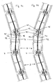
- the wedge surfaces 21, 22 form stop surfaces which limit the pivoting range of two adjacent links 3 to one another, as shown in FIGS FIGS. 5a and 5c evident. In In each case two adjacent wedge surfaces 21, 22 abut one another flatly against these outer pivot positions, which reduces the pressure load on the walls 28 forming the wedge surfaces 21, 22. Because of these stops, two mutually adjacent links 3 can each be pivoted by 18 ° relative to the central position in which the central axes 15 of both links are aligned with each other.
- the bushing 13 and the receiving bushing 37 are formed integrally with the link half 29 in order to reduce the production cost and the variety of parts.
- the link halves 29 are made of translucent polycarbonate PC, which can be colored differently.
- the pivot pin 40 is made of polyacetyl resin POM. The favorable sliding properties of this material lead to a reduced joint wear.
- the pivot pin 40 has on its outer circumference a polygon profiling 35. It is a regular Zwanzigeck, so that adjacent profile surfaces each enclose an angle of 18 ° with each other.
- the spherical bearing bushings 13 have on their inner circumference a corresponding polygon profiling 33.
- the two Proflierept 33, 35 form a detent; two adjacent members 3 are held in different pivot positions in increments of 18 ° latching, as shown in the Fig. 5a - 5c is apparent.
- the abutment surfaces 21, 22 ensure, as stated above, that in the present case exactly three detent positions exist, namely the rectilinear center position (FIG. Fig.
- Fig. 9 a further embodiment is shown in which the detent from webs 24 of the joint bearing parts 13 and grooves 25 of the propeller shaft parts 18 is formed (grooving).
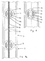
- bending elements 42 In the interior of the support arm 2 forming members 3 extend two bending elements 42 ( Fig. 7a - 7c ). These are spring steel strips with a width of about 5 mm and a thickness of about 0.4 mm, which are electrically insulated by an insulating film 43.
- recesses 16 are provided in the pivot bearing bushes 13, bushings 44 in the pivot pins 40 and recesses 31 in the reinforcing walls 30.
- the bushings 44 expand outwardly funnel-shaped, so that even in the angled detent positions ( Fig. 7b, 7c ), no sharp edges occur, where the striking of the spring steel strip could lead to increased wear.
- the passage 44 occupies a relatively large volume of the pivot pin 40, it is advantageous for the stability of the pivot pin 40, if it is formed in one piece and not in two pieces, as is the case for example in the spherical bearing bushings 13.
- the passage 44 in the propeller shaft part 40 is preferably closed in the manner of a bore in itself, so that the bending element 42 and the power lines are enclosed and held on all sides.
- the spring steel strips 42 are bending elastic over the entire adjustment range of the support arm 2.
- the flexures 42 are each guided in duplicate (not shown in the figures) and thus reinforced. If two adjacent links 3 are in an angular position to each other, this leads to a bending of the bending elements 42 (s. Fig. 7b, 7c ) and thereby to a relief of the common connection joint 4, since the bending element 42 absorbs a part of the forces acting on the connecting joint 4 due to the bending.
- the bending elements 42 abut on the recesses 16 forming ends 45 of the joint bearing bushes 13, which are rounded for this purpose.
- the sockets 13 are formed reinforced on their side facing away from the respective member 3 side 46, since the largest loads occur here.
- the two bending elements 42 are used as mutually insulated conductors for power supply from the base part 8 to the lamp body 5.
- Fig. 10 shown is the lamp body 5 by means of a rod-shaped control element 9 about its central axis by 18 ° to both sides pivotally to allow a certain lateral adjustability of the illumination.
Landscapes
- Engineering & Computer Science (AREA)
- General Engineering & Computer Science (AREA)
- Non-Portable Lighting Devices Or Systems Thereof (AREA)
- Fastening Of Light Sources Or Lamp Holders (AREA)
- Pivots And Pivotal Connections (AREA)
- Endoscopes (AREA)
- Arrangements Of Lighting Devices For Vehicle Interiors, Mounting And Supporting Thereof, Circuits Therefore (AREA)
- Vessels And Coating Films For Discharge Lamps (AREA)
Claims (20)
- Lampe (1) comportant un corps de lampe (5) et un bras support (2), dont une extrémité porte le corps de lampe (5) et dont l'extrémité opposée est conçue pour l'assemblage à un socle (8), le bras support (2) comportant une série continue de maillons (3), qui sont assemblés les uns aux autres par l'intermédiaire d'articulations de liaison (4), caractérisée en ce que le bras support (2) comporte au moins un élément de flexion (42) qui s'étend sur les articulations de liaison (4) proches du socle et est disposé sensiblement à l'intérieur des maillons (3) et qui, en cours d'utilisation de la lampe (1), absorbe par flexion au moins une partie des couples de rotation exercés sur les articulations de liaison (4) proches du socle.
- Lampe selon la revendication 1, caractérisée en ce que, en cours d'utilisation de la lampe (1), l'élément de flexion (42) absorbe au moins 30 %, de préférence au moins 50 % des couples de rotation exercés sur les articulations de liaison (4) proches du socle.
- Lampe selon la revendication 1 ou 2, caractérisée en ce que l'élément de flexion (42) est élastiquement flexible sur l'ensemble de la zone de réglage du bras support (2).
- Lampe selon l'une quelconque des revendications 1 à 3, caractérisée en ce que l'élément de flexion (42) est renforcé dans la zone proche du socle.
- Lampe selon l'une quelconque des revendications 1 à 4, caractérisée en ce que l'élément de flexion (42) est utilisé pour l'acheminement du courant depuis le socle (8) vers le corps de lampe (5).
- Lampe selon l'une quelconque des revendications 1 à 5, caractérisée en ce qu'au moins un des éléments articulés (13, 40, 18), formant une articulation de liaison (4), comporte des passages (44) ou évidements (16, 20) pour le guidage de l'élément de flexion (42) et/ou des lignes d'alimentation électriques.
- Lampe selon l'une quelconque des revendications 1 à 6, caractérisée en ce que les maillons (3) sont réalisés sensiblement en matière plastique transparente, de préférence en polycarbonate (PC).
- Lampe selon l'une quelconque des revendications 1 à 7, caractérisée en ce qu'au moins une des surfaces de glissement d'une articulation de liaison (4) est formée par un matériau qui possède un comportement de glissement et/ou d'usure plus favorable que celui du matériau des maillons (3) correspondants.
- Lampe selon la revendication 8, caractérisée en ce que la surface de glissement est réalisée en résine de polyacétyle (POM).
- Lampe selon l'une quelconque des revendications 1 à 9, caractérisée en ce que l'articulation de liaison (4) est réalisée de manière encliquetable entre deux maillons (3) adjacents.
- Lampe selon la revendication 10, caractérisée en ce qu'un maillon (3) est apte à pivoter par rapport à un maillon (3) adjacent autour d'un axe de pivotement (23) et peut être bloqué dans exactement trois positions par rapport à cet axe de pivotement (23).
- Lampe selon la revendication 11, caractérisée en ce que les axes médians (15) de deux maillons (3) sont alignés l'un à l'autre dans la position de blocage centrale.
- Lampe selon la revendication 11 ou 12, caractérisée en ce que dans les deux positions de blocage extérieures, les axes médians (15) des deux maillons (3) délimitent entre eux respectivement le même angle.
- Lampe selon l'une quelconque des revendications 11 à 13, caractérisée en ce que le blocage d'une articulation de liaison (4) est formé par un profilage (33, 35) sur au moins une des deux surfaces de glissement.
- Lampe selon l'une quelconque des revendications 1 à 14, caractérisée en ce que deux maillons (3) adjacents, au niveau de leur zone de liaison, ont une section de forme conique avec les pointes de cône orientées l'une vers l'autre.
- Lampe selon l'une quelconque des revendications 1 à 15, caractérisée en ce que la zone de pivotement d'un maillon (3) par rapport à un maillon (3) adjacent est limitée de telle sorte que les axes médians (15) des deux maillons délimitent entre eux un angle de 40° maximum, de préférence 30° maximum, de préférence 20° maximum.
- Lampe selon l'une quelconque des revendications 1 à 16, caractérisée en ce que le bras support (2) comporte au moins 5, de préférence au moins 10, encore mieux au mieux 15 maillons (3).
- Lampe selon l'une quelconque des revendications 1 à 17, caractérisée en ce que sensiblement tous les maillons (3) sont identiques.
- Lampe selon la revendication 18, caractérisée en ce qu'un maillon (3) est formé sensiblement par deux moitiés d'un seul tenant.
- Lampe selon l'une quelconque des revendications 1 à 19, caractérisée en ce que respectivement deux maillons (3) adjacents sont reliés entre eux par une articulation rotative (4), dont l'axe de rotation (23) est orienté perpendiculairement aux axes médians (15) des deux maillons (3).
Applications Claiming Priority (2)
| Application Number | Priority Date | Filing Date | Title |
|---|---|---|---|
| DE20009799U DE20009799U1 (de) | 2000-05-31 | 2000-05-31 | Leuchte |
| DE20009799U | 2000-05-31 |
Publications (3)
| Publication Number | Publication Date |
|---|---|
| EP1160508A2 EP1160508A2 (fr) | 2001-12-05 |
| EP1160508A3 EP1160508A3 (fr) | 2004-07-14 |
| EP1160508B1 true EP1160508B1 (fr) | 2008-07-16 |
Family
ID=7942288
Family Applications (1)
| Application Number | Title | Priority Date | Filing Date |
|---|---|---|---|
| EP01108408A Expired - Lifetime EP1160508B1 (fr) | 2000-05-31 | 2001-04-03 | Lampe |
Country Status (3)
| Country | Link |
|---|---|
| EP (1) | EP1160508B1 (fr) |
| AT (1) | ATE401531T1 (fr) |
| DE (2) | DE20009799U1 (fr) |
Families Citing this family (4)
| Publication number | Priority date | Publication date | Assignee | Title |
|---|---|---|---|---|
| NO320544B1 (no) * | 2003-09-19 | 2005-12-19 | Niels S Jorgensen | Formbar anordning |
| GB0413576D0 (en) * | 2004-06-15 | 2004-07-21 | Maiolino Simona | Lamp |
| IT1402816B1 (it) * | 2010-07-01 | 2013-09-27 | Benocci | Lampada |
| DE102014115085A1 (de) * | 2014-10-16 | 2016-04-21 | "Durable" Hunke & Jochheim Gmbh & Co. Kommanditgesellschaft | Bedienmodul und Beleuchtungssystem |
Family Cites Families (9)
| Publication number | Priority date | Publication date | Assignee | Title |
|---|---|---|---|---|
| US1279803A (en) * | 1917-09-29 | 1918-09-24 | George F Watson | Light-support. |
| GB460441A (en) * | 1935-07-25 | 1937-01-25 | Harold Cyril Cooper | Improvements in or relating to articulated joints |
| DE8707756U1 (de) * | 1987-05-30 | 1987-08-20 | Schladitz, Klaus, 8201 Prutting | Niederspannungsschiene mit aufsteckbarem Strahler |
| AT391182B (de) * | 1988-07-27 | 1990-08-27 | Pesau Karin Mag | Elektrische lampe |
| EP0381909A1 (fr) * | 1988-10-18 | 1990-08-16 | Associate Designers, S.A. | Bras de support |
| DE9010337U1 (de) * | 1990-07-09 | 1990-09-13 | Chin-Song, Chen, Taipeh/T'ai-pei | Tischlampe |
| EP0664870A1 (fr) * | 1992-10-17 | 1995-08-02 | Pius Ponticelli | Composant pour fabriquer un objet utilitaire flexible |
| US5521803A (en) * | 1994-08-05 | 1996-05-28 | Eckert; Lee H. | Flashlight with flexible core |
| US6042245A (en) * | 1998-04-02 | 2000-03-28 | Stanley; Terry D. | Switch attachment |
-
2000
- 2000-05-31 DE DE20009799U patent/DE20009799U1/de not_active Expired - Lifetime
-
2001
- 2001-04-03 AT AT01108408T patent/ATE401531T1/de not_active IP Right Cessation
- 2001-04-03 DE DE50114110T patent/DE50114110D1/de not_active Expired - Fee Related
- 2001-04-03 EP EP01108408A patent/EP1160508B1/fr not_active Expired - Lifetime
Also Published As
| Publication number | Publication date |
|---|---|
| EP1160508A2 (fr) | 2001-12-05 |
| EP1160508A3 (fr) | 2004-07-14 |
| ATE401531T1 (de) | 2008-08-15 |
| DE50114110D1 (de) | 2008-08-28 |
| DE20009799U1 (de) | 2001-12-06 |
Similar Documents
| Publication | Publication Date | Title |
|---|---|---|
| DE69713297T2 (de) | Scharnier mit elastisch überdehnbarem offenanschlag sowie eine ein derartiges scharnier umfassende brille | |
| EP1844204A2 (fr) | Charniere a articulations multiples | |
| EP0516598B1 (fr) | Pince avec introduction avant et côté facultative | |
| EP3602709B1 (fr) | Dispositif de guidage de lignes | |
| EP1048809A1 (fr) | Charnière avec un bras de charnière | |
| EP3253994B1 (fr) | Maillon et chaîne de manutention à maillon | |
| DE60213570T2 (de) | Vorrichtung zur halterung und justierung eines bauteils | |
| DE3408202C2 (de) | Federscharnier zwischen zwei Teilen einer Brille | |
| EP1160508B1 (fr) | Lampe | |
| EP1625270B1 (fr) | Compas pour porte | |
| DE69115196T2 (de) | Rasterdecke. | |
| WO1990015911A1 (fr) | Charniere | |
| EP2556298B1 (fr) | Dispositif d'éclairage à del pivotante | |
| DE2932423C3 (de) | Schirm | |
| DE3813088C2 (fr) | ||
| EP1143194A1 (fr) | Lampadaire | |
| EP1827770B1 (fr) | Cisaille, en particulier taille-haie | |
| DE3719483A1 (de) | Schraubklemme zum anschluss elektrischer leitungen | |
| DE19856684A1 (de) | Gelenk | |
| DE3724236C1 (de) | Druckkappe fuer verstellbare Spannglieder aufweisende Spanneinrichtungen,insbesondere fuer Spannzwingen | |
| DE19744638A1 (de) | Leuchte | |
| DE29803998U1 (de) | Zange | |
| DE69208187T2 (de) | Möbelscharnier | |
| AT521835B1 (de) | Kabelkanal | |
| EP1022079B1 (fr) | Outil pour le remplacement d'une plaquette de coupe |
Legal Events
| Date | Code | Title | Description |
|---|---|---|---|
| PUAI | Public reference made under article 153(3) epc to a published international application that has entered the european phase |
Free format text: ORIGINAL CODE: 0009012 |
|
| AK | Designated contracting states |
Kind code of ref document: A2 Designated state(s): AT BE CH CY DE DK ES FI FR GB GR IE IT LI LU MC NL PT SE TR |
|
| AX | Request for extension of the european patent |
Free format text: AL;LT;LV;MK;RO;SI |
|
| PUAL | Search report despatched |
Free format text: ORIGINAL CODE: 0009013 |
|
| AK | Designated contracting states |
Kind code of ref document: A3 Designated state(s): AT BE CH CY DE DK ES FI FR GB GR IE IT LI LU MC NL PT SE TR |
|
| AX | Request for extension of the european patent |
Extension state: AL LT LV MK RO SI |
|
| 17P | Request for examination filed |
Effective date: 20041209 |
|
| AKX | Designation fees paid |
Designated state(s): AT BE CH CY DE DK ES FI FR GB GR IE IT LI LU MC NL PT SE TR |
|
| GRAP | Despatch of communication of intention to grant a patent |
Free format text: ORIGINAL CODE: EPIDOSNIGR1 |
|
| GRAS | Grant fee paid |
Free format text: ORIGINAL CODE: EPIDOSNIGR3 |
|
| GRAA | (expected) grant |
Free format text: ORIGINAL CODE: 0009210 |
|
| AK | Designated contracting states |
Kind code of ref document: B1 Designated state(s): AT BE CH CY DE DK ES FI FR GB GR IE IT LI LU MC NL PT SE TR |
|
| REG | Reference to a national code |
Ref country code: GB Ref legal event code: FG4D Free format text: NOT ENGLISH |
|
| REG | Reference to a national code |
Ref country code: CH Ref legal event code: EP |
|
| REF | Corresponds to: |
Ref document number: 50114110 Country of ref document: DE Date of ref document: 20080828 Kind code of ref document: P |
|
| REG | Reference to a national code |
Ref country code: IE Ref legal event code: FG4D Free format text: LANGUAGE OF EP DOCUMENT: GERMAN |
|
| NLV1 | Nl: lapsed or annulled due to failure to fulfill the requirements of art. 29p and 29m of the patents act | ||
| PG25 | Lapsed in a contracting state [announced via postgrant information from national office to epo] |
Ref country code: PT Free format text: LAPSE BECAUSE OF FAILURE TO SUBMIT A TRANSLATION OF THE DESCRIPTION OR TO PAY THE FEE WITHIN THE PRESCRIBED TIME-LIMIT Effective date: 20081216 Ref country code: NL Free format text: LAPSE BECAUSE OF FAILURE TO SUBMIT A TRANSLATION OF THE DESCRIPTION OR TO PAY THE FEE WITHIN THE PRESCRIBED TIME-LIMIT Effective date: 20080716 Ref country code: ES Free format text: LAPSE BECAUSE OF FAILURE TO SUBMIT A TRANSLATION OF THE DESCRIPTION OR TO PAY THE FEE WITHIN THE PRESCRIBED TIME-LIMIT Effective date: 20081027 |
|
| PG25 | Lapsed in a contracting state [announced via postgrant information from national office to epo] |
Ref country code: FI Free format text: LAPSE BECAUSE OF FAILURE TO SUBMIT A TRANSLATION OF THE DESCRIPTION OR TO PAY THE FEE WITHIN THE PRESCRIBED TIME-LIMIT Effective date: 20080716 |
|
| REG | Reference to a national code |
Ref country code: IE Ref legal event code: FD4D |
|
| PG25 | Lapsed in a contracting state [announced via postgrant information from national office to epo] |
Ref country code: IE Free format text: LAPSE BECAUSE OF FAILURE TO SUBMIT A TRANSLATION OF THE DESCRIPTION OR TO PAY THE FEE WITHIN THE PRESCRIBED TIME-LIMIT Effective date: 20080716 Ref country code: DK Free format text: LAPSE BECAUSE OF FAILURE TO SUBMIT A TRANSLATION OF THE DESCRIPTION OR TO PAY THE FEE WITHIN THE PRESCRIBED TIME-LIMIT Effective date: 20080716 |
|
| PLBE | No opposition filed within time limit |
Free format text: ORIGINAL CODE: 0009261 |
|
| STAA | Information on the status of an ep patent application or granted ep patent |
Free format text: STATUS: NO OPPOSITION FILED WITHIN TIME LIMIT |
|
| 26N | No opposition filed |
Effective date: 20090417 |
|
| PG25 | Lapsed in a contracting state [announced via postgrant information from national office to epo] |
Ref country code: IT Free format text: LAPSE BECAUSE OF FAILURE TO SUBMIT A TRANSLATION OF THE DESCRIPTION OR TO PAY THE FEE WITHIN THE PRESCRIBED TIME-LIMIT Effective date: 20080716 |
|
| BERE | Be: lapsed |
Owner name: TOBIAS GRAU Effective date: 20090430 |
|
| PGFP | Annual fee paid to national office [announced via postgrant information from national office to epo] |
Ref country code: DE Payment date: 20090624 Year of fee payment: 9 |
|
| REG | Reference to a national code |
Ref country code: CH Ref legal event code: PL |
|
| GBPC | Gb: european patent ceased through non-payment of renewal fee |
Effective date: 20090403 |
|
| REG | Reference to a national code |
Ref country code: FR Ref legal event code: ST Effective date: 20091231 |
|
| PG25 | Lapsed in a contracting state [announced via postgrant information from national office to epo] |
Ref country code: CH Free format text: LAPSE BECAUSE OF NON-PAYMENT OF DUE FEES Effective date: 20090430 Ref country code: SE Free format text: LAPSE BECAUSE OF FAILURE TO SUBMIT A TRANSLATION OF THE DESCRIPTION OR TO PAY THE FEE WITHIN THE PRESCRIBED TIME-LIMIT Effective date: 20081016 Ref country code: LI Free format text: LAPSE BECAUSE OF NON-PAYMENT OF DUE FEES Effective date: 20090430 |
|
| PG25 | Lapsed in a contracting state [announced via postgrant information from national office to epo] |
Ref country code: FR Free format text: LAPSE BECAUSE OF NON-PAYMENT OF DUE FEES Effective date: 20091222 Ref country code: MC Free format text: LAPSE BECAUSE OF NON-PAYMENT OF DUE FEES Effective date: 20090430 Ref country code: GB Free format text: LAPSE BECAUSE OF NON-PAYMENT OF DUE FEES Effective date: 20090403 |
|
| PG25 | Lapsed in a contracting state [announced via postgrant information from national office to epo] |
Ref country code: BE Free format text: LAPSE BECAUSE OF NON-PAYMENT OF DUE FEES Effective date: 20090430 |
|
| PG25 | Lapsed in a contracting state [announced via postgrant information from national office to epo] |
Ref country code: AT Free format text: LAPSE BECAUSE OF NON-PAYMENT OF DUE FEES Effective date: 20090403 |
|
| PG25 | Lapsed in a contracting state [announced via postgrant information from national office to epo] |
Ref country code: GR Free format text: LAPSE BECAUSE OF FAILURE TO SUBMIT A TRANSLATION OF THE DESCRIPTION OR TO PAY THE FEE WITHIN THE PRESCRIBED TIME-LIMIT Effective date: 20081017 |
|
| PG25 | Lapsed in a contracting state [announced via postgrant information from national office to epo] |
Ref country code: DE Free format text: LAPSE BECAUSE OF NON-PAYMENT OF DUE FEES Effective date: 20101103 |
|
| PG25 | Lapsed in a contracting state [announced via postgrant information from national office to epo] |
Ref country code: LU Free format text: LAPSE BECAUSE OF NON-PAYMENT OF DUE FEES Effective date: 20090403 |
|
| PG25 | Lapsed in a contracting state [announced via postgrant information from national office to epo] |
Ref country code: TR Free format text: LAPSE BECAUSE OF FAILURE TO SUBMIT A TRANSLATION OF THE DESCRIPTION OR TO PAY THE FEE WITHIN THE PRESCRIBED TIME-LIMIT Effective date: 20080716 |
|
| PG25 | Lapsed in a contracting state [announced via postgrant information from national office to epo] |
Ref country code: CY Free format text: LAPSE BECAUSE OF FAILURE TO SUBMIT A TRANSLATION OF THE DESCRIPTION OR TO PAY THE FEE WITHIN THE PRESCRIBED TIME-LIMIT Effective date: 20080716 |