EP1161095A2 - Appareil pour la reproduction audio et vidéo avec une fonction de suspension - Google Patents
Appareil pour la reproduction audio et vidéo avec une fonction de suspension Download PDFInfo
- Publication number
- EP1161095A2 EP1161095A2 EP01302712A EP01302712A EP1161095A2 EP 1161095 A2 EP1161095 A2 EP 1161095A2 EP 01302712 A EP01302712 A EP 01302712A EP 01302712 A EP01302712 A EP 01302712A EP 1161095 A2 EP1161095 A2 EP 1161095A2
- Authority
- EP
- European Patent Office
- Prior art keywords
- audio
- video
- output
- suspension
- time
- Prior art date
- Legal status (The legal status is an assumption and is not a legal conclusion. Google has not performed a legal analysis and makes no representation as to the accuracy of the status listed.)
- Granted
Links
Images



Classifications
-
- H—ELECTRICITY
- H04—ELECTRIC COMMUNICATION TECHNIQUE
- H04N—PICTORIAL COMMUNICATION, e.g. TELEVISION
- H04N5/00—Details of television systems
- H04N5/76—Television signal recording
- H04N5/78—Television signal recording using magnetic recording
- H04N5/782—Television signal recording using magnetic recording on tape
- H04N5/783—Adaptations for reproducing at a rate different from the recording rate
-
- H—ELECTRICITY
- H04—ELECTRIC COMMUNICATION TECHNIQUE
- H04N—PICTORIAL COMMUNICATION, e.g. TELEVISION
- H04N21/00—Selective content distribution, e.g. interactive television or video on demand [VOD]
- H04N21/20—Servers specifically adapted for the distribution of content, e.g. VOD servers; Operations thereof
- H04N21/23—Processing of content or additional data; Elementary server operations; Server middleware
- H04N21/236—Assembling of a multiplex stream, e.g. transport stream, by combining a video stream with other content or additional data, e.g. inserting a URL [Uniform Resource Locator] into a video stream, multiplexing software data into a video stream; Remultiplexing of multiplex streams; Insertion of stuffing bits into the multiplex stream, e.g. to obtain a constant bit-rate; Assembling of a packetised elementary stream
- H04N21/2368—Multiplexing of audio and video streams
-
- H—ELECTRICITY
- H04—ELECTRIC COMMUNICATION TECHNIQUE
- H04N—PICTORIAL COMMUNICATION, e.g. TELEVISION
- H04N21/00—Selective content distribution, e.g. interactive television or video on demand [VOD]
- H04N21/40—Client devices specifically adapted for the reception of or interaction with content, e.g. set-top-box [STB]; Operations thereof
- H04N21/43—Processing of content or additional data, e.g. demultiplexing additional data from a digital video stream; Elementary client operations, e.g. monitoring of home network or synchronising decoder's clock; Client middleware
- H04N21/4302—Content synchronisation processes, e.g. decoder synchronisation
- H04N21/4307—Synchronising the rendering of multiple content streams or additional data on devices, e.g. synchronisation of audio on a mobile phone with the video output on the TV screen
- H04N21/43072—Synchronising the rendering of multiple content streams or additional data on devices, e.g. synchronisation of audio on a mobile phone with the video output on the TV screen of multiple content streams on the same device
-
- H—ELECTRICITY
- H04—ELECTRIC COMMUNICATION TECHNIQUE
- H04N—PICTORIAL COMMUNICATION, e.g. TELEVISION
- H04N21/00—Selective content distribution, e.g. interactive television or video on demand [VOD]
- H04N21/40—Client devices specifically adapted for the reception of or interaction with content, e.g. set-top-box [STB]; Operations thereof
- H04N21/43—Processing of content or additional data, e.g. demultiplexing additional data from a digital video stream; Elementary client operations, e.g. monitoring of home network or synchronising decoder's clock; Client middleware
- H04N21/434—Disassembling of a multiplex stream, e.g. demultiplexing audio and video streams, extraction of additional data from a video stream; Remultiplexing of multiplex streams; Extraction or processing of SI; Disassembling of packetised elementary stream
- H04N21/4341—Demultiplexing of audio and video streams
-
- H—ELECTRICITY
- H04—ELECTRIC COMMUNICATION TECHNIQUE
- H04N—PICTORIAL COMMUNICATION, e.g. TELEVISION
- H04N21/00—Selective content distribution, e.g. interactive television or video on demand [VOD]
- H04N21/40—Client devices specifically adapted for the reception of or interaction with content, e.g. set-top-box [STB]; Operations thereof
- H04N21/43—Processing of content or additional data, e.g. demultiplexing additional data from a digital video stream; Elementary client operations, e.g. monitoring of home network or synchronising decoder's clock; Client middleware
- H04N21/44—Processing of video elementary streams, e.g. splicing a video clip retrieved from local storage with an incoming video stream or rendering scenes according to encoded video stream scene graphs
- H04N21/4402—Processing of video elementary streams, e.g. splicing a video clip retrieved from local storage with an incoming video stream or rendering scenes according to encoded video stream scene graphs involving reformatting operations of video signals for household redistribution, storage or real-time display
- H04N21/440209—Processing of video elementary streams, e.g. splicing a video clip retrieved from local storage with an incoming video stream or rendering scenes according to encoded video stream scene graphs involving reformatting operations of video signals for household redistribution, storage or real-time display for formatting on an optical medium, e.g. DVD
-
- H—ELECTRICITY
- H04—ELECTRIC COMMUNICATION TECHNIQUE
- H04N—PICTORIAL COMMUNICATION, e.g. TELEVISION
- H04N9/00—Details of colour television systems
- H04N9/79—Processing of colour television signals in connection with recording
- H04N9/80—Transformation of the television signal for recording, e.g. modulation, frequency changing; Inverse transformation for playback
- H04N9/804—Transformation of the television signal for recording, e.g. modulation, frequency changing; Inverse transformation for playback involving pulse code modulation of the colour picture signal components
- H04N9/8042—Transformation of the television signal for recording, e.g. modulation, frequency changing; Inverse transformation for playback involving pulse code modulation of the colour picture signal components involving data reduction
Definitions
- Data of video and audio used in the DVD (digital versatile disc) or the like are compressed and coded by the MPEG or a relevant scheme (Dolby Digital, DTS, or the like), and, then, are divided into packets, each of which is provided with attached time information (PTS: presentation time stamp) for the synchronization purpose.
- PTS presentation time stamp
- SCR system clock reference
- Video information is coded by the unit of one field or one frame that is a basis of presentation, and audio information is also coded by the unit of one frame.
- One frame of audio information generally differs in length from one frame of video information.
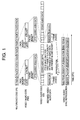
- PTS is attached to each unit for coding. When one packet includes a plurality of audio frames, however, PTS is attached only to the first frame. In the example of Fig.1, therefore, audio data frames 1, 3, and 5 each have PTS attached thereto, whereas audio data frames 2, 4, and 6 are not provided with attached PTS. These data frames are thus lacking in time information.
- video information is presented on a display device such as a TV set, so that timings of presentation are restricted by synchronizing clock timings of the device. For example, therefore, the system time clock is counted based on the synchronizing clock timing, and pictures are presented at such timings as the count corresponds to the PTSs.
- Audio data has a frame length different from that of video frames, so that the audio data is not reproduced at the same timing as the video data. The audio data is reproduced by determining its own output timings based on PTSs of the audio data. With respect to an audio data frame that has no PTS attached-thereto, audio data is output continuously without any gap following the previous frame, thereby maintaining synchronization with the video presentation.
- a special form of reproduction such as pause or slow reproduction may be performed.
- pause reproduction a picture corresponding to the paused timing is repeatedly presented for paused video presentation, and audio data is suspended.
- slow reproduction short duration of pause and play is repeated as many times as necessary.
- Fig.2 shows a case in which the user instructs pause during presentation of a second video picture.
- the video picture 2 is displayed again after the completion of current presentation of the video picture 2.
- the video picture 2 is repeatedly displayed.
- a third audio frame is being reproduced. Accordingly, reproduction of audio data is suspended after the end of reproduction of the audio frame 3.
- the audio data frame 4 is not provided with a PTS, however, it is uncertain when the reproduction of the audio data frame 4 should be resumed. In such a case, the audio data frame 4 having no PTS may be discarded as shown in Conventional Audio Reproduction Method 1 of Fig.2, and the next audio data frame 5 having a PTS may be presented at the timing specified by this PTS. When this is done, however, audio for the audio data frame 4 is lost, resulting in silent reproduction of video information.
- a video signal includes a first frame comprised of two fields 1T and 1B, a second frame comprised of three fields 2T, 2B, and 2T, a third frame comprised of two fields 3B and 3T, a fourth frame comprised of three fields 4B, 4T, and 4B, and a fifth frame comprised of two fields 5T and 5B.
- the first frame comprised of the two fields 1T and 1B is displayed first, and, then, these two fields 1T and 1B are repeated again in the same manner as during pause operation.
- the second frame comprised of the three fields 2T, 2B, and 2T are displayed, followed by the first two fields 2T and 2B of these three fields 2T, 2B, and 2T being displayed again.
- the third frame comprised of the two fields 3B and 3T is displayed, and, then, these two fields 3B and 3T are repeated again in the same manner as during pause operation.
- the user may assume half-as-slow reproduction, yet the passage of time does not correspond to 2T that is two times as long as T.
- the actual passage of time is TS, which means a failure to achieve half-as-slow reproduction.
- the related-art method repeats reproduction for pause operation by treating one frame as simply having two fields.
- actual reproduction time ends up differing from the supposed time length.
- the invention provides an apparatus for reproducing video and audio including a video decoder which receives video data coded by a unit of a first time length, an audio decoder which receives audio data coded by a unit of a second time length different from the first time length, and a synchronization control unit which suspends video output of the video decoder and audio output of the audio decoder, and resumes the audio output a certain time period after resuming the video output where the certain time period is identical in length to a period from the suspension of the video output to the suspension of the audio output.
- the apparatus measures a time period from the suspension of output of the video decoder to the suspension of output of the audio decoder, and resumes the audio decoder output upon passage of time the same length as the measured time period after resuming the video decoder output.
- the apparatus measures a time period from a signal indicative of suspension of reproduction of the video decoder and the audio decoder to a first audio frame change signal. Then, a suspension instruction directed to the audio decoder is cancelled upon passage of the time period identical to the measured time period after the instruction for resuming the video decoder.
- the apparatus as described above is such. that a period of the suspension of video output is adjusted according to how many fields are included in one frame of the video data. For example, the number of fields that are repeated for presentation during the suspension of video output is equal to the number of fields presented during normal reproduction. This makes it possible to make the time passage for slow reproduction an exact number of times as long as the time passage for normal reproduction.
- a method of reproducing video and audio includes the steps of outputting video data after receiving and decoding the video data coded by a unit of a first time length, outputting audio data after receiving and decoding the audio data coded by a unit of a second time length different from the first time length, suspending video output and audio output, resuming the video output, and resuming the audio output a certain time period after the resuming the video output where the certain time period corresponds to a period from the suspension of the video output to the suspension of the audio output.
- Fig.4 is a block diagram of an audio and video decoder according to the present invention.
- An audio and video decoder 10 of Fig.4 includes a synchronization control unit 11, an audio decoder 12, a video decoder 13, and an STC counter 14.
- the audio decoder 12 receives an audio stream separated from a multiplexed code stream, and decodes the received stream to produce audio output. Further, the audio decoder 12 supplies PTS (time information) and an audio-frame-change signal indicative of each boundary between audio frames to the synchronization control unit 11 where the PTS is extracted from the audio stream.
- PTS time information
- audio-frame-change signal indicative of each boundary between audio frames
- the video decoder 13 receives a video stream separated from the multiplexed code stream, and decodes the received stream to produce video output. Further, the video decoder 13 supplies PTS (time information) and presentation-period information indicative of a valid period of video presentation to the synchronization control unit 11 where the PTS is extracted from the video stream.
- PTS time information
- presentation-period information indicative of a valid period of video presentation
- the STC counter 14 receives a time clock signal, and counts a system time clock STC based on the time clock signal.
- the counting of the system time clock STC is controlled in terms of counting or suspending of counting by an STC count valid/invalid instruction supplied from the synchronization control unit 11.
- the synchronization control unit 11 receives the time clock, the system time clock STC, and the TV synchronizing signal, and attends to synchronization control of the audio output of the audio decoder 12 and the video output of the video decoder 13. Further, the synchronization control unit 11 receives a suspension instruction signal indicative of suspension (pause) of the audio and video reproduction, and controls the audio decoder 12 and the video decoder 13 based on the suspension instruction signal to suspend the audio and video reproduction.
- the synchronization control unit 11 turns output suspension/reproduction signals thereof into a suspension state where the output suspension reproduction signals are supplied to the audio decoder 12 and the video decoder 13. As a result, the audio decoder 12 and the video decoder 13 are instructed to suspend respective reproductions.
- the synchronization control unit 11 instructs the STC counter 14 to cancel the counting of the STC, thereby stopping the counting of the system time clock STC.
- the audio decoder 12 generally produces audio output by the unit of one audio frame.
- the output suspension/reproduction signal thereof indicates the suspension state
- the audio output is suspended after the completion of reproduction of the currently reproduced audio frame. Accordingly, actual timing of audio output suspension corresponds to the audio-frame-change signal that appears first after the instruction of suspension.
- the synchronization control unit 11 measures a time period from the suspension of video reproduction to the actual suspension of audio reproduction.
- the suspension of video reproduction is marked by the timing at which the output suspension/reproduction signal supplied to the audio decoder 12 is changed to the suspension state, and the actual suspension of audio reproduction is marked by the first audio-frame-change signal.
- this time period is measured by counting the time clock signal from the rising edge of the output suspension/reproduction signal to the first audio-frame-change signal.
- the synchronization control unit 11 cancels the suspension instruction directed to the audio decoder 12, the video decoder 13, and the STC counter 14. Since the video output can be presented at a video display timing, the output suspension/reproduction signal to the video decoder 13 is disengaged from the suspension state thereof in response to the timing of the TV synchronizing signal. The count valid instruction is supplied to the STC counter 14 at such timing as indicated by the display period information from the video decoder 13 and the TV synchronizing signal. This cancels the suspension of counting.
- the timing at which the audio reproduction is resumed i.e., the timing at which the synchronization control unit 11 cancels the suspension instruction directed to the audio decoder 12 is different form that of the related art.
- the audio reproduction may wait for an audio frame having a PTS attached thereto, or may be resumed for the time being, followed by timing adjustment performed upon arrival of an audio frame having a PTS attached thereto.
- the present invention measures a time period from the signal indicative of suspension of reproduction of the video decoder and the audio decoder to the first audio-frame-change signal. Then, the suspension instruction directed to the audio decoder 12 is cancelled upon passage of the time period identical to the measured time period after the instruction for resuming the video decoder.
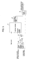
- Fig.5 is a circuit diagram showing a partial configuration of the synchronization control unit 11 that measures a time period from the suspension of video output to the actual suspension of audio output.
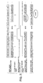
- Fig.6 is a timing chart showing operation of the configuration shown in Fig.4 and Fig.5.
- the synchronization control unit 11 supplies a signal indicative of video suspension to the video decoder 13 as shown in (d) of Fig.6.
- the timing at which this signal is supplied corresponds to the timing of the TV synchronizing signal shown in (b) of Fig.6.
- the provision of the signal indicative of video suspension corresponds to the change to the suspension stage of the output suspension/reproduction signal supplied form the synchronization control unit 11 to the video decoder 13 in Fig.4.
- the synchronization control unit 11 supplies a signal indicative of audio suspension to the audio decoder 12 as shown in (f) of Fig.6.
- the rising and falling edge detection unit 22 shown in Fig.5 detects a rising edge of the signal indicative of video suspension so as to set the set-reset flip-flop 23. This results in an count enable input to the up/down counter 21 being enabled.
- the signal indicative of video suspension that is HIGH is supplied to an up/down input of the up/down counter 21, thereby placing it in a condition for count-up operation.
- the up/down counter 21 starts to count the time clock. The way the count increases is shown as an incremental slope shown in (h) of Fig.6.
- the audio-frame-change signal is supplied from-the audio decoder 12 to the synchronization control unit 11 as shown in (e) of Fig.6.
- This audio-frame-change signal is supplied to a reset input of the set-reset flip-flop 23 shown in Fig.5, thereby resetting the set-reset flip-flop 23.
- the count enable input to the up/down counter 21 is disabled, so that the up/down counter 21 stops the counting-up operation. In this manner, a time period from the suspension of vide reproduction to the actual suspension of audio output is stored in the up/down counter 21 as a count of the time clock pulses.
- the output of the non-zero detection unit 24 supplied to the logic sum circuit 25 changes from HIGH to LOW.
- the logic sum circuit 25 obtains a logic sum (OR) of the output of the non-zero detection unit 24 and the signal indicative of video suspension, thereby producing the signal indicative of audio suspension as shown in (f) of Fig.6.
- the OR operation by the logic sum circuit 25 is performed in consideration of reliability of intended circuit operation even under presence of minor timing displacement.
- the signal indicative of audio suspension may be generated according to the HIGH/LOW status of the non-zero detection unit 24 (i.e., according to zero/non-zero status of the output of the up/down counter 21).
- the signal indicative of audio suspension as shown in (f) of Fig.6 is supplied from the synchronization control unit 11 to the audio decoder 12.
- a period during which the audio output is actually suspended corresponds to the period shown in (g) of Fig.6.
- the period for audio suspension shown in (g) of Fig.6 is the same length as the period of the signal indicative of video suspension shown in (d) of Fig.6, i.e., is the same length as the period of video output suspension. Accordingly, the audio output, when resumed, is kept in synchronization with the video output.
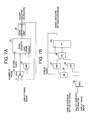
- Figs.7A and 7B are circuit diagrams showing a partial configuration of the synchronization control unit 11 that generates the signal indicative of video suspension.
- Figs.7A and 7B are different portions of the circuit that generates the signal indicative of video suspension, and together constitute the entirety of this circuit.
- the circuit portion shown in Fig.7A includes a selector 31, an AND circuit 32, a down counter 33, and a zero-detection circuit 34.
- the circuit portion shown in Fig.7B includes AND circuits 35 through 37, an inverter 38, an OR circuit 39, and a flip-flop 40.
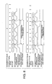
- Fig.8 is a timing chart for explaining operation of the circuit of Fig.7A and Fig.7B. In the following, operation of the circuit of Figs.7A and 7B will be described with reference to Fig.8.
- the selector 31 shown in Fig.7A receives information indicative of the number of frames from the video decoder 13 where the information is derived by decoding the video stream.
- the information indicative of the number of fields specifies whether the currently presented frame is comprised of two fields or comprised of three fields.
- the selector 31 selects "1" when the information indicative of the number of fields indicates two fields, and selects "2" when the information indicative of the number of fields specifies three fields.
- the selected value is loaded into the down counter 33.
- Fig.8 in (a) through (f), shows a case in which the information indicative of the number of fields specifies two fields, with the down counter 33 downloading "1".
- Fig.8, in (g) through (1) shows a case in which the information indicative of the number of fields specifies three fields, with the down counter 33 downloading "2".
- (a) and (g) of Fig.8 illustrate the information indicative of the number of fields
- (c) and (i) of Fig.8 demonstrate the count by the counter.
- the value that is loaded into the down counter 33 is subjected to countdown operation based on the system clock signal.
- the output of the down counter 33 is supplied to the zero-detection circuit 34.
- validity indicating information that is output from the zero-detection circuit 34 becomes HIGH as shown in (d) and (j) of Fig.8.
- the validity indicating information and a display timing signal ((d) and (h) of Fig.8) are supplied to the AND circuit 32, and the output of the AND circuit 32 is supplied to a load request input of the down counter 33. Accordingly, a new value is loaded into the down counter 33 each time the count becomes zero.
- the validity indicating information that is output from the zero-detection circuit 34 is supplied to the circuit of Fig.7B, and is combined with a user-suspension-instruction signal responsive to a user request or the like. As a result, the signal indicative of video suspension as shown in (f) and (1) of Fig.8 is obtained.
- the value selected according to the number of fields is subjected to countdown operation where the number of fields is indicated by the information indicative of the number of fields.
- a timing at which the count of the countdown becomes zero is detected, so that a time period corresponding to the total number of fields per frame can be measured.
- the signal indicative of video signal suspension is generated. This makes it possible to repeat presentation of fields as many as there are fields, the number of which is two or three indicated by the information indicative of the number of fields.
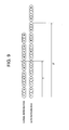
- Fig.9 is an illustrative drawing showing the way the slow reproduction is performed according to the present invention when two-field frames and three-field frames are mixed together.
- the slow reproduction of Fig.9 corresponds to a case in which a short duration of pause and a short duration of play are repeated based on the signal indicative of video suspension generated by the circuit of Figs.7A and 7B as shown in Fig.8.
- a video signal includes a first frame comprised of two fields 1T and 1B, a second frame comprised of three fields 2T, 2B, and 2T, a third frame comprised of two fields 3B and 3T, a fourth frame comprised of three fields 4B, 4T, and 4B, and a fifth frame comprised of two fields 5T and 5B.
- the first frame comprised of the two fields 1T and 1B is displayed first, and, then, these two fields 1T and 1B are repeated again as part of pause operation.
- the second frame comprised of the three fields 2T, 2B, and 2T are displayed, followed by these three fields 2T, 2B, and 2T being displayed again during pause operation.
- the third frame comprised of the two fields 3B and 3T is displayed, and, then, these two fields 3B and 3T are repeated again as part of pause operation.
- the time length having passed for the slow reproduction corresponds to the time length 2T that is two times the time length T required for normal reproduction of the first through third frames.
- the user assumes half-as-slow reproduction, and the passage of time for the slow reproduction exactly corresponds to two times the time length T. Further, when one-third-slow reproduction is intended, for example, the actual passage of time for slow reproduction exactly becomes three times as long.
Landscapes
- Engineering & Computer Science (AREA)
- Multimedia (AREA)
- Signal Processing (AREA)
- Television Signal Processing For Recording (AREA)
- Signal Processing For Digital Recording And Reproducing (AREA)
Applications Claiming Priority (2)
| Application Number | Priority Date | Filing Date | Title |
|---|---|---|---|
| JP2000163646 | 2000-05-31 | ||
| JP2000163646A JP4035277B2 (ja) | 2000-05-31 | 2000-05-31 | 映像・音声再生装置及び映像・音声再生方法 |
Publications (3)
| Publication Number | Publication Date |
|---|---|
| EP1161095A2 true EP1161095A2 (fr) | 2001-12-05 |
| EP1161095A3 EP1161095A3 (fr) | 2002-07-31 |
| EP1161095B1 EP1161095B1 (fr) | 2019-03-06 |
Family
ID=18667375
Family Applications (1)
| Application Number | Title | Priority Date | Filing Date |
|---|---|---|---|
| EP01302712.3A Expired - Lifetime EP1161095B1 (fr) | 2000-05-31 | 2001-03-23 | Appareil pour la reproduction audio et vidéo avec une fonction de suspension |
Country Status (3)
| Country | Link |
|---|---|
| US (1) | US7027714B2 (fr) |
| EP (1) | EP1161095B1 (fr) |
| JP (1) | JP4035277B2 (fr) |
Cited By (2)
| Publication number | Priority date | Publication date | Assignee | Title |
|---|---|---|---|---|
| WO2004112391A1 (fr) | 2003-06-12 | 2004-12-23 | Sony Corporation | Dispositif d'enregistrement de donnees video et de donnees audio |
| EP1367830A3 (fr) * | 2002-05-28 | 2006-06-14 | Fujitsu Limited | Décodeur de données et procédé de décodage de données |
Families Citing this family (7)
| Publication number | Priority date | Publication date | Assignee | Title |
|---|---|---|---|---|
| US7088398B1 (en) * | 2001-12-24 | 2006-08-08 | Silicon Image, Inc. | Method and apparatus for regenerating a clock for auxiliary data transmitted over a serial link with video data |
| TW200531023A (en) * | 2004-03-12 | 2005-09-16 | Ali Corp | Method for rapid video synchronization adjustment |
| JP4613860B2 (ja) * | 2005-04-13 | 2011-01-19 | パナソニック株式会社 | Mpeg符号化ストリーム復号装置 |
| WO2009063572A1 (fr) * | 2007-11-16 | 2009-05-22 | Panasonic Corporation | Terminal portable et procédé de sortie vidéo |
| JP2009180972A (ja) * | 2008-01-31 | 2009-08-13 | Panasonic Corp | オーディオレジューム再生装置及びオーディオレジューム再生方法 |
| GB2472992A (en) * | 2009-08-25 | 2011-03-02 | Zarlink Semiconductor Inc | Reduction of clicking sounds in audio data streams |
| US8966062B1 (en) * | 2012-01-31 | 2015-02-24 | Intuit Inc. | Method and system for synchronizing user access to information presented in two or more media formats |
Family Cites Families (7)
| Publication number | Priority date | Publication date | Assignee | Title |
|---|---|---|---|---|
| US5953485A (en) * | 1992-02-07 | 1999-09-14 | Abecassis; Max | Method and system for maintaining audio during video control |
| JP3255308B2 (ja) | 1992-12-18 | 2002-02-12 | ソニー株式会社 | データ再生装置 |
| US5815634A (en) * | 1994-09-30 | 1998-09-29 | Cirrus Logic, Inc. | Stream synchronization method and apparatus for MPEG playback system |
| JPH08107543A (ja) * | 1994-10-07 | 1996-04-23 | Sony Corp | 文字表示制御装置 |
| US5818634A (en) * | 1996-08-05 | 1998-10-06 | Motorola, Inc. | Dual mode optical Magnifier system |
| JP3491533B2 (ja) | 1998-07-24 | 2004-01-26 | ヤマハ株式会社 | ディジタルオーディオデータの再生方法及び装置 |
| US6654539B1 (en) * | 1998-10-26 | 2003-11-25 | Sony Corporation | Trick playback of digital video data |
-
2000
- 2000-05-31 JP JP2000163646A patent/JP4035277B2/ja not_active Expired - Lifetime
-
2001
- 2001-03-19 US US09/810,497 patent/US7027714B2/en not_active Expired - Lifetime
- 2001-03-23 EP EP01302712.3A patent/EP1161095B1/fr not_active Expired - Lifetime
Cited By (3)
| Publication number | Priority date | Publication date | Assignee | Title |
|---|---|---|---|---|
| EP1367830A3 (fr) * | 2002-05-28 | 2006-06-14 | Fujitsu Limited | Décodeur de données et procédé de décodage de données |
| WO2004112391A1 (fr) | 2003-06-12 | 2004-12-23 | Sony Corporation | Dispositif d'enregistrement de donnees video et de donnees audio |
| EP1633138A4 (fr) * | 2003-06-12 | 2010-11-10 | Sony Corp | Dispositif d'enregistrement de donnees video et de donnees audio |
Also Published As
| Publication number | Publication date |
|---|---|
| JP2001346147A (ja) | 2001-12-14 |
| EP1161095B1 (fr) | 2019-03-06 |
| JP4035277B2 (ja) | 2008-01-16 |
| US7027714B2 (en) | 2006-04-11 |
| EP1161095A3 (fr) | 2002-07-31 |
| US20010048808A1 (en) | 2001-12-06 |
Similar Documents
| Publication | Publication Date | Title |
|---|---|---|
| US6314234B1 (en) | System for storing and reproducing multiplexed data | |
| US8004609B2 (en) | Amplifier, correcting method of correcting difference in processing time between video signal and audio signal, and correcting system | |
| EP0618728A2 (fr) | Synchronisation d'information audio/vidéo | |
| US20010055469A1 (en) | Decoder and reproducing unit | |
| US7027714B2 (en) | Apparatus for reproduction of video and audio with suspension function | |
| US8154964B2 (en) | Data processing device, data processing method, program, program recording medium, data recording medium, and data structure | |
| US7359621B2 (en) | Recording apparatus | |
| US8488017B2 (en) | Image processing apparatus to transmit moving image data | |
| US8160422B2 (en) | Data recording device, data recording method, data processing device, data processing method, program, program recording medium, data recording medium, and data structure | |
| CN100586176C (zh) | 用于视频同步的设备和方法 | |
| US7584511B2 (en) | Data processing apparatus, data processing method, program, program recording medium, data recording medium, and data structure | |
| US20080044164A1 (en) | Data Processing Device, Data Processing Method, Program, Program Recording Medium, Data Recording Medium, and Data Structure | |
| US20110064391A1 (en) | Video-audio playback apparatus | |
| JP5202193B2 (ja) | 画像処理装置及び方法 | |
| CN101116335B (zh) | 用于重放视频信号和一个或多个音频信号的方法和设备 | |
| CN101171639A (zh) | 通过补充附加50i格式数据项来创作24p音频/视频数据流的方法和设备 | |
| US8346059B2 (en) | Data processing device, data processing method, program, program recording medium, data recording medium, and data structure | |
| JP2004032607A (ja) | ディジタル映像再生装置 | |
| JP2004104300A (ja) | 光ディスク再生装置 | |
| JP2004128870A (ja) | 映像復号出力装置 | |
| JP2738342B2 (ja) | ビデオ符号復号化装置 | |
| US8107796B2 (en) | Data processing device, data processing method, program, program recording medium, data recording medium, and data structure | |
| JP3671969B2 (ja) | データ多重方法及び多重データ復号方法 | |
| JPH1127601A (ja) | テレビ信号判別装置及びテレビ信号判別方法 | |
| KR970003166A (ko) | 한국형 예약 녹화 시스템에서의 초기 화면 정보 녹화 장치 |
Legal Events
| Date | Code | Title | Description |
|---|---|---|---|
| PUAI | Public reference made under article 153(3) epc to a published international application that has entered the european phase |
Free format text: ORIGINAL CODE: 0009012 |
|
| AK | Designated contracting states |
Kind code of ref document: A2 Designated state(s): AT BE CH CY DE DK ES FI FR GB GR IE IT LI LU MC NL PT SE TR |
|
| AX | Request for extension of the european patent |
Free format text: AL;LT;LV;MK;RO;SI |
|
| PUAL | Search report despatched |
Free format text: ORIGINAL CODE: 0009013 |
|
| AK | Designated contracting states |
Kind code of ref document: A3 Designated state(s): AT BE CH CY DE DK ES FI FR GB GR IE IT LI LU MC NL PT SE TR |
|
| AX | Request for extension of the european patent |
Free format text: AL;LT;LV;MK;RO;SI |
|
| 17P | Request for examination filed |
Effective date: 20021127 |
|
| AKX | Designation fees paid |
Designated state(s): DE FR |
|
| STAA | Information on the status of an ep patent application or granted ep patent |
Free format text: STATUS: EXAMINATION IS IN PROGRESS |
|
| REG | Reference to a national code |
Ref country code: DE Ref legal event code: R079 Ref document number: 60151075 Country of ref document: DE Free format text: PREVIOUS MAIN CLASS: H04N0007240000 Ipc: H04N0021236800 |
|
| RIC1 | Information provided on ipc code assigned before grant |
Ipc: H04N 9/804 20060101ALI20180807BHEP Ipc: H04N 21/43 20110101ALI20180807BHEP Ipc: H04N 21/4402 20110101ALI20180807BHEP Ipc: H04N 5/783 20060101ALI20180807BHEP Ipc: H04N 21/2368 20110101AFI20180807BHEP Ipc: H04N 21/434 20110101ALI20180807BHEP |
|
| GRAP | Despatch of communication of intention to grant a patent |
Free format text: ORIGINAL CODE: EPIDOSNIGR1 |
|
| STAA | Information on the status of an ep patent application or granted ep patent |
Free format text: STATUS: GRANT OF PATENT IS INTENDED |
|
| INTG | Intention to grant announced |
Effective date: 20180925 |
|
| GRAS | Grant fee paid |
Free format text: ORIGINAL CODE: EPIDOSNIGR3 |
|
| GRAA | (expected) grant |
Free format text: ORIGINAL CODE: 0009210 |
|
| STAA | Information on the status of an ep patent application or granted ep patent |
Free format text: STATUS: THE PATENT HAS BEEN GRANTED |
|
| RIN1 | Information on inventor provided before grant (corrected) |
Inventor name: KONO, TADAYOSHI Inventor name: OHTA, MITSUHIKO |
|
| AK | Designated contracting states |
Kind code of ref document: B1 Designated state(s): DE FR |
|
| REG | Reference to a national code |
Ref country code: DE Ref legal event code: R096 Ref document number: 60151075 Country of ref document: DE |
|
| REG | Reference to a national code |
Ref country code: DE Ref legal event code: R097 Ref document number: 60151075 Country of ref document: DE |
|
| PLBE | No opposition filed within time limit |
Free format text: ORIGINAL CODE: 0009261 |
|
| STAA | Information on the status of an ep patent application or granted ep patent |
Free format text: STATUS: NO OPPOSITION FILED WITHIN TIME LIMIT |
|
| 26N | No opposition filed |
Effective date: 20191209 |
|
| PGFP | Annual fee paid to national office [announced via postgrant information from national office to epo] |
Ref country code: DE Payment date: 20200310 Year of fee payment: 20 |
|
| PGFP | Annual fee paid to national office [announced via postgrant information from national office to epo] |
Ref country code: FR Payment date: 20200214 Year of fee payment: 20 |
|
| REG | Reference to a national code |
Ref country code: DE Ref legal event code: R082 Ref document number: 60151075 Country of ref document: DE Representative=s name: HL KEMPNER PATENTANWALT, RECHTSANWALT, SOLICIT, DE |
|
| REG | Reference to a national code |
Ref country code: DE Ref legal event code: R071 Ref document number: 60151075 Country of ref document: DE |