EP1161292B1 - Trenneinrichtung für das aussondern von feststoffen aus einem flüssigkeits- feststoff- gemisch - Google Patents
Trenneinrichtung für das aussondern von feststoffen aus einem flüssigkeits- feststoff- gemisch Download PDFInfo
- Publication number
- EP1161292B1 EP1161292B1 EP00910549A EP00910549A EP1161292B1 EP 1161292 B1 EP1161292 B1 EP 1161292B1 EP 00910549 A EP00910549 A EP 00910549A EP 00910549 A EP00910549 A EP 00910549A EP 1161292 B1 EP1161292 B1 EP 1161292B1
- Authority
- EP
- European Patent Office
- Prior art keywords
- solids
- screen
- flow
- sieve
- liquid
- Prior art date
- Legal status (The legal status is an assumption and is not a legal conclusion. Google has not performed a legal analysis and makes no representation as to the accuracy of the status listed.)
- Expired - Lifetime
Links
- 239000007787 solid Substances 0.000 title claims abstract description 128
- 239000008247 solid mixture Substances 0.000 title claims abstract description 12
- 238000012545 processing Methods 0.000 claims abstract description 6
- 239000002351 wastewater Substances 0.000 claims abstract description 5
- 239000007788 liquid Substances 0.000 claims description 48
- 239000000203 mixture Substances 0.000 claims description 16
- 238000000034 method Methods 0.000 claims description 11
- 239000007921 spray Substances 0.000 claims description 10
- 230000008569 process Effects 0.000 claims description 7
- 238000012216 screening Methods 0.000 claims description 6
- 239000000725 suspension Substances 0.000 claims description 6
- 239000010865 sewage Substances 0.000 claims description 5
- 230000009471 action Effects 0.000 claims description 3
- 244000144619 Abrus precatorius Species 0.000 claims description 2
- 230000000694 effects Effects 0.000 claims description 2
- 238000001914 filtration Methods 0.000 claims description 2
- 238000007790 scraping Methods 0.000 claims 2
- 230000006835 compression Effects 0.000 claims 1
- 238000007906 compression Methods 0.000 claims 1
- 230000000149 penetrating effect Effects 0.000 abstract description 2
- 238000012549 training Methods 0.000 description 23
- 238000013461 design Methods 0.000 description 10
- XLYOFNOQVPJJNP-UHFFFAOYSA-N water Substances O XLYOFNOQVPJJNP-UHFFFAOYSA-N 0.000 description 8
- 238000005406 washing Methods 0.000 description 6
- 230000035699 permeability Effects 0.000 description 5
- 239000012530 fluid Substances 0.000 description 4
- 230000015572 biosynthetic process Effects 0.000 description 3
- 238000005345 coagulation Methods 0.000 description 3
- 230000015271 coagulation Effects 0.000 description 3
- 238000005755 formation reaction Methods 0.000 description 3
- 238000012546 transfer Methods 0.000 description 3
- 230000008901 benefit Effects 0.000 description 2
- 238000004140 cleaning Methods 0.000 description 2
- 238000011109 contamination Methods 0.000 description 2
- 238000012986 modification Methods 0.000 description 2
- 230000004048 modification Effects 0.000 description 2
- 230000000737 periodic effect Effects 0.000 description 2
- 238000000926 separation method Methods 0.000 description 2
- 238000007873 sieving Methods 0.000 description 2
- 239000002689 soil Substances 0.000 description 2
- 238000011144 upstream manufacturing Methods 0.000 description 2
- 206010010774 Constipation Diseases 0.000 description 1
- 241000196324 Embryophyta Species 0.000 description 1
- 241000237858 Gastropoda Species 0.000 description 1
- 238000009825 accumulation Methods 0.000 description 1
- 230000001154 acute effect Effects 0.000 description 1
- 238000011001 backwashing Methods 0.000 description 1
- 238000000151 deposition Methods 0.000 description 1
- 238000001514 detection method Methods 0.000 description 1
- 238000000605 extraction Methods 0.000 description 1
- 238000011010 flushing procedure Methods 0.000 description 1
- 230000005484 gravity Effects 0.000 description 1
- 238000003780 insertion Methods 0.000 description 1
- 230000037431 insertion Effects 0.000 description 1
- 239000000463 material Substances 0.000 description 1
- 238000012806 monitoring device Methods 0.000 description 1
- 239000002245 particle Substances 0.000 description 1
- 230000001737 promoting effect Effects 0.000 description 1
- 238000005086 pumping Methods 0.000 description 1
- 239000011435 rock Substances 0.000 description 1
- 238000010408 sweeping Methods 0.000 description 1
- 238000004065 wastewater treatment Methods 0.000 description 1
Images


Classifications
-
- B—PERFORMING OPERATIONS; TRANSPORTING
- B01—PHYSICAL OR CHEMICAL PROCESSES OR APPARATUS IN GENERAL
- B01D—SEPARATION
- B01D29/00—Filters with filtering elements stationary during filtration, e.g. pressure or suction filters, not covered by groups B01D24/00 - B01D27/00; Filtering elements therefor
- B01D29/01—Filters with filtering elements stationary during filtration, e.g. pressure or suction filters, not covered by groups B01D24/00 - B01D27/00; Filtering elements therefor with flat filtering elements
- B01D29/014—Filters with filtering elements stationary during filtration, e.g. pressure or suction filters, not covered by groups B01D24/00 - B01D27/00; Filtering elements therefor with flat filtering elements with curved filtering elements
-
- B—PERFORMING OPERATIONS; TRANSPORTING
- B01—PHYSICAL OR CHEMICAL PROCESSES OR APPARATUS IN GENERAL
- B01D—SEPARATION
- B01D29/00—Filters with filtering elements stationary during filtration, e.g. pressure or suction filters, not covered by groups B01D24/00 - B01D27/00; Filtering elements therefor
- B01D29/01—Filters with filtering elements stationary during filtration, e.g. pressure or suction filters, not covered by groups B01D24/00 - B01D27/00; Filtering elements therefor with flat filtering elements
-
- B—PERFORMING OPERATIONS; TRANSPORTING
- B01—PHYSICAL OR CHEMICAL PROCESSES OR APPARATUS IN GENERAL
- B01D—SEPARATION
- B01D29/00—Filters with filtering elements stationary during filtration, e.g. pressure or suction filters, not covered by groups B01D24/00 - B01D27/00; Filtering elements therefor
- B01D29/44—Edge filtering elements, i.e. using contiguous impervious surfaces
- B01D29/445—Bar screens
-
- B—PERFORMING OPERATIONS; TRANSPORTING
- B01—PHYSICAL OR CHEMICAL PROCESSES OR APPARATUS IN GENERAL
- B01D—SEPARATION
- B01D29/00—Filters with filtering elements stationary during filtration, e.g. pressure or suction filters, not covered by groups B01D24/00 - B01D27/00; Filtering elements therefor
- B01D29/50—Filters with filtering elements stationary during filtration, e.g. pressure or suction filters, not covered by groups B01D24/00 - B01D27/00; Filtering elements therefor with multiple filtering elements, characterised by their mutual disposition
- B01D29/52—Filters with filtering elements stationary during filtration, e.g. pressure or suction filters, not covered by groups B01D24/00 - B01D27/00; Filtering elements therefor with multiple filtering elements, characterised by their mutual disposition in parallel connection
-
- B—PERFORMING OPERATIONS; TRANSPORTING
- B01—PHYSICAL OR CHEMICAL PROCESSES OR APPARATUS IN GENERAL
- B01D—SEPARATION
- B01D29/00—Filters with filtering elements stationary during filtration, e.g. pressure or suction filters, not covered by groups B01D24/00 - B01D27/00; Filtering elements therefor
- B01D29/62—Regenerating the filter material in the filter
- B01D29/64—Regenerating the filter material in the filter by scrapers, brushes, nozzles, or the like, acting on the cake side of the filtering element
- B01D29/6407—Regenerating the filter material in the filter by scrapers, brushes, nozzles, or the like, acting on the cake side of the filtering element brushes
- B01D29/6423—Regenerating the filter material in the filter by scrapers, brushes, nozzles, or the like, acting on the cake side of the filtering element brushes with a translational movement with respect to the filtering element
-
- B—PERFORMING OPERATIONS; TRANSPORTING
- B01—PHYSICAL OR CHEMICAL PROCESSES OR APPARATUS IN GENERAL
- B01D—SEPARATION
- B01D29/00—Filters with filtering elements stationary during filtration, e.g. pressure or suction filters, not covered by groups B01D24/00 - B01D27/00; Filtering elements therefor
- B01D29/62—Regenerating the filter material in the filter
- B01D29/64—Regenerating the filter material in the filter by scrapers, brushes, nozzles, or the like, acting on the cake side of the filtering element
- B01D29/6469—Regenerating the filter material in the filter by scrapers, brushes, nozzles, or the like, acting on the cake side of the filtering element scrapers
- B01D29/6476—Regenerating the filter material in the filter by scrapers, brushes, nozzles, or the like, acting on the cake side of the filtering element scrapers with a rotary movement with respect to the filtering element
-
- B—PERFORMING OPERATIONS; TRANSPORTING
- B01—PHYSICAL OR CHEMICAL PROCESSES OR APPARATUS IN GENERAL
- B01D—SEPARATION
- B01D29/00—Filters with filtering elements stationary during filtration, e.g. pressure or suction filters, not covered by groups B01D24/00 - B01D27/00; Filtering elements therefor
- B01D29/62—Regenerating the filter material in the filter
- B01D29/64—Regenerating the filter material in the filter by scrapers, brushes, nozzles, or the like, acting on the cake side of the filtering element
- B01D29/6469—Regenerating the filter material in the filter by scrapers, brushes, nozzles, or the like, acting on the cake side of the filtering element scrapers
- B01D29/6484—Regenerating the filter material in the filter by scrapers, brushes, nozzles, or the like, acting on the cake side of the filtering element scrapers with a translatory movement with respect to the filtering element
-
- B—PERFORMING OPERATIONS; TRANSPORTING
- B01—PHYSICAL OR CHEMICAL PROCESSES OR APPARATUS IN GENERAL
- B01D—SEPARATION
- B01D29/00—Filters with filtering elements stationary during filtration, e.g. pressure or suction filters, not covered by groups B01D24/00 - B01D27/00; Filtering elements therefor
- B01D29/62—Regenerating the filter material in the filter
- B01D29/66—Regenerating the filter material in the filter by flushing, e.g. counter-current air-bumps
- B01D29/68—Regenerating the filter material in the filter by flushing, e.g. counter-current air-bumps with backwash arms, shoes or nozzles
- B01D29/684—Regenerating the filter material in the filter by flushing, e.g. counter-current air-bumps with backwash arms, shoes or nozzles with a translatory movement with respect to the filtering element
-
- B—PERFORMING OPERATIONS; TRANSPORTING
- B01—PHYSICAL OR CHEMICAL PROCESSES OR APPARATUS IN GENERAL
- B01D—SEPARATION
- B01D29/00—Filters with filtering elements stationary during filtration, e.g. pressure or suction filters, not covered by groups B01D24/00 - B01D27/00; Filtering elements therefor
- B01D29/88—Filters with filtering elements stationary during filtration, e.g. pressure or suction filters, not covered by groups B01D24/00 - B01D27/00; Filtering elements therefor having feed or discharge devices
- B01D29/94—Filters with filtering elements stationary during filtration, e.g. pressure or suction filters, not covered by groups B01D24/00 - B01D27/00; Filtering elements therefor having feed or discharge devices for discharging the filter cake, e.g. chutes
-
- B—PERFORMING OPERATIONS; TRANSPORTING
- B01—PHYSICAL OR CHEMICAL PROCESSES OR APPARATUS IN GENERAL
- B01D—SEPARATION
- B01D33/00—Filters with filtering elements which move during the filtering operation
- B01D33/333—Filters with filtering elements which move during the filtering operation with individual filtering elements moving along a closed path
-
- B—PERFORMING OPERATIONS; TRANSPORTING
- B01—PHYSICAL OR CHEMICAL PROCESSES OR APPARATUS IN GENERAL
- B01D—SEPARATION
- B01D33/00—Filters with filtering elements which move during the filtering operation
- B01D33/70—Filters with filtering elements which move during the filtering operation having feed or discharge devices
- B01D33/76—Filters with filtering elements which move during the filtering operation having feed or discharge devices for discharging the filter cake, e.g. chutes
-
- B—PERFORMING OPERATIONS; TRANSPORTING
- B01—PHYSICAL OR CHEMICAL PROCESSES OR APPARATUS IN GENERAL
- B01D—SEPARATION
- B01D2201/00—Details relating to filtering apparatus
- B01D2201/48—Overflow systems
Definitions
- the invention relates to a method for separating solids from a liquid-solid mixture flowing in in a certain direction of flow (Suspension), for example waste water, in a channel, container or the like by collecting the solids in a liquid-solid mixture transversely to its flow direction penetrating screen area and the mechanical removal of which is forced from the screen surface for further treatment, as well as a separating device for carrying out the Process.
- a certain direction of flow for example waste water
- the technical equipment mentioned here with which solids are made a liquid-solid mixture with the help of a computing device to be separated out which is basically a - regularly fixed - sieve and comprises a scraper which can be moved relative to it and with which the solids trapped by the sieve from the liquid flow from the Sieve are removed, work regularly so that the solids go up out of in a channel, a channel, a container or the like flowing fluid supported naturally or by pumping devices be excavated.
- This results in the area above the flowing Liquid a corresponding space requirement for the transfer of the solids in a container, a conveyor system or a further processing system, e.g. to Washing of these solids, furthermore heavy and small volume Solids in the area of the bottom of the channel, container etc.
- the invention is based on the object, starting from the the above-mentioned procedure to avoid towering superstructures and especially reliable even heavy and small volume solids in the To detect the bottom area of the channel, container or the like and to be conveyed away more easily, in particular without the collection and removal floatable to thwart solids.
- the procedure according to the invention is such that the Removal of the solid from the sieve surface to the bottom of the channel, Container or the like by mechanical to the floor Attack is forced, which is followed in the course of further processing Solid crushed and / or from the bottom area of the channel, container or the like is transported outside the flow.
- the shredded one Crushing device originating, so far pre-crushed solid repeatedly fed to the shredding and / or the one to be removed Repeat solids before final removal to the floor area fed.
- a separating device for carrying out the method, those for the separation of solids from one in a certain Direction of incoming flow of a liquid-solid mixture (Suspension), for example waste water, in a channel, container or the like with one in the liquid-solid mixture this across provided its flow direction used computing device which comprises a sieve and a scraper, the latter of which is from the sieve solids collected from the mixture by force stripped, which is characterized in that the scraper the from the sieve stripped solids in a bottom area of the channel, container or the like is directed towards forced removal and that in a crushing device - chopping, Shredder device or the like - for the further transport of the appropriately crushed solid passing through the sieve with the Liquid flow to a sewage treatment plant or the like and / or a Transport device for the transfer from the scraper to Soil stripped off the floor area outside the flow is provided.
- a liquid-solid mixture for example waste water
- the current concept is made of a solid-liquid mixture capture the solid by means of a sieve and this sieved solid upwards out of the flowing liquid to emphasize, basically leave.
- the sieve trapped solid down to the bottom of the channel, channel, container or promoted and from there either after crushing by the Sieve the flowing liquid added again or on different Transported away from this floor area.
- the Removed solids can be removed - as long as they are not Crushing (shredding or the like) through the sieve into the outflow Liquid can be fed - without risk of contamination and without Odor nuisance dissipated through closed pipes become.
- the floor area for receiving the scraper from the sieve is preferably delimited to that extent Collection space formed above the bottom or bottom of the channel or of the container or the like and / or at least partially by a Recess is formed below the sole or floor level.
- This Collection space is to the transport device in the sense of a transfer of the Solid connected the - in addition to pipes etc. for the management of the Solid - as a vacuum source like a suction pump, in the sense of a Evacuation of pressurized vacuum space or the like or as Overpressure source like pressure pump, in the sense of a pressure build-up pressurized pressure chamber or the like or as a mechanical Conveying device like screw conveyor, also in the successive Sections of different conveying direction is formed.
- the sieve of the computing device is from its lower one Edge area seen from the vertical against the direction of flow inclined, such that the solid collected by the sieve as far as can be freely grasped by the scraper; on the To this extent, screenings are not subjected to shear force, floatable Solids are taken more reliably towards the floor area because the flow of this buoyant solid when it hits the sieve Reflected floor area. At this angle of inclination upwards seen inclined towards the flow direction, i.e.
- the screens of such computing devices are preferably arranged at which the clearers are positively guided in terms of their trajectory; this are in particular sieves with in a vertical plane according to the dimensioning the sieve openings parallel spaced rods, patemost rakes, Filter stage rake or perforated plates with pushing or rotating on them along guided scraper of known design.
- the scraper in training as a nozzle spray device can in principle Mitströmraum be arranged effectively, especially if the Jet direction of the nozzles with a correspondingly steep angle to the floor is directed.
- the nozzles are preferred with regard to their jet direction but effectively arranged in the counterflow direction.
- wire spiral or spiral rake devices as a computing device, where one or more are arranged side by side Sieve jack screw devices are used which are in the lower Area not have fixed storage, because of the necessary Attack of the snail on the screen jacket a slight inclination of the side-by-side sieve jackets viewed from the bottom in Flow direction can be provided, but this angle of inclination can be chosen much steeper in the direction of the vertical than that of the previous screen screw systems is the case that the solid from the Lift the mixture out upwards.
- the computing device can be located within the Coag or the like in terms of its upper edge below the dimensioned upper limit of the channel or the like be that with a correspondingly above-average amount of mixture Emergency overflow takes place. This is also in the event of failure of the Determination of the liquid level over the bottom of the channel, container or the like of importance. Operation of the here in question Plant runs regularly in such a way that the permeability of the sieve through collected solid within a standstill period of the Computing device increases so that the liquid level of the Mixture rises upstream of the sieve. When you reach one predetermined level value, the scraper takes action and frees the sieve from the collected solid.
- the solid gets into the bottom area, the preferably as a collecting space - trough-shaped across the width of the channel, Extending container or the like - is formed and is by this Accumulation in the floor area further processed. So far a periodic mode of operation.
- Towards a mastery of an above average Feed level of the liquid to be freed from solids - for example in heavy rain - can also limit the upper edge of the computing device within a channel to an area below the Channel limitation in a further preferred embodiment of the invention therefor be ensured that the flow resistance (hydraulic resistance) of the computing device or its part acting as a sieve or as such a computing device in the area of higher fluid levels is less that the openings of the sieve as seen from the bottom increasingly more spacious at the top and therefore with regard to the liquid are designed to be more permeable.
- the permeability staggered upwards of the sieve shows a particular advantage of the one in the foreground Removal of solids to the floor; in a previously known Funding in the opposite direction would result in finer solids in the course of upward discharge through the widening sieve openings get into the area in the direction of flow behind the sieve and thus insofar as they destroy the sieving result achieved.
- the further treatment of the solid stripped down from the sieve can be done in different ways that can be combined. As far as crushable solid is obtained, this can be done by means of a Shredding device (shredder, shredder) can be shredded, namely so far that the crushed solid matter through the sieve openings be carried on with the liquid and in so far one Subsequent treatment is subject to, as for the - coarse - solids cleaned liquid of the mixture is provided.
- Especially preferred embodiment of the invention will be one for this purpose provided comminuting device-derived solids repeated by returning the shredder to the entrance area Shredding process to get as much of the crushable solid in this way through the sieve with the further processed liquid and the removal from the To withdraw liquid flow out. So far there are only left the non-comminutable solids for removal from the Floor area or collecting space to the outside of the flow, especially in a supply area above the upper edge of the Channel, container or the like.
- Another preferred treatment variant for the in the Collecting space in the bottom area of the channel, container or the like consists in the fact that this solid, in particular a solid that cannot be comminuted before it is finally removed from the mixture flow in one insofar upstream operating phase in terms of removal dissipated, but then first led back to the floor area - if necessary several times -, causing an intensive washing of this accumulated solid takes place before the final removal those that should preferably be sent to a landfill or incinerator To free the solid from organic buildup if possible.
- Preferred embodiments of the invention are in subclaims 2 and 4 to 12 recorded.
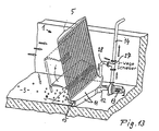
- a channel 2 is such by side and front break clarifies that without the otherwise facing the viewer Leg wall of the cross-sectionally U-shaped channel insight into the Inside the channel at a point where the separation of Solids from a channel in the direction of the arrow - see drawing - flowing liquid mixture has in the direction of flow a computing device 1 solids of a larger constitution contains than after.
- the flow according to the computing device in the Existing liquid is only supposed to have a correspondingly small volume Sieve of the computing device containing passing solids, which in the course of Further treatment - sewage treatment plant etc. - can be processed.
- the computing device first removes all solid particles that are the size of the Screen openings of the screen of the computing device can not pass through.
- the channel 2 in broken-down representation as an example of a number of other facilities is a solid-liquid mixture (suspension) in question standing type in a certain direction of flow. It can besides a channel, as is known in wastewater treatment, in Act similarly to a container in which liquid to be clarified for the purpose of separating solids in compliance with a certain flow direction is entered, or the like functionally similar facilities more.
- the computing device 1 is on the floor 3 of the total designated 2 Coil placed on, in the example of Figure 1 with respect to lower edge dimension of the sieve 4, here consisting of a bar rake 5, whose rods 5 'are evenly spaced and parallel in the vertical plane thus forming the sieve openings between adjacent bars are arranged in such a way that the rods face down in the upper edge area of a collecting space housing 11, which a collecting space 9 below the bar rake 5 in the bottom area of the channel 2, with this Bottom area flush, defined.
- the collection room 9 is thus without impairing the continuous cross-section Clot created so that this design of the computing device also can be retrofitted into any existing channel.
- the rod rake 5 is assigned a scraper designated 6 in total, with respect to its parallel to the bar rakes 5 ' Guide 8 is movable such that it with its rake tines 7 in the Sieve openings between the parallel bar rakes 5 ' engages when the scraper 6 is moved from top to bottom while the Rake tines 7 in the course of the backward movement of the scraper 6 from below are located above the screen openings between the bars 5 '. On this way, it accumulates in the sieve area of the bar rake 5 Solid only in the direction of the bottom of the channel 2 and thus in promoted the area of the collecting room 9.
- the through the collective housing 11 enclosed collection space 9 is arranged by a downstream Connection line 12 to the suction inlet of a submersible pump 13 connected, the pump-side output in a discharge line 14th opens, which - as shown - in this case after in the collecting room 9 Wiping the bar rake 5 through the scraper 6 conveyed solid 15 in guides an area above the upper edge boundary of the channel 2, be it in a container or another transport device or one further treatment device, for example drainage device, generally with the aim of depositing this solid.
- the exemplary embodiment according to FIG. 2 shows a computing device 1 with a Bar rake 5, the bars 5 'of which are led to the bottom 3 of the channel 2. Seen in the flow direction in front of the bottom ends of the rods 5 'is in the channel bottom 3 a downward, transversely to the direction of flow running collecting space channel 10 embedded in the channel floor 3, as this shows the figure 2.
- the computing device 1 corresponds to that of described embodiment according to Figure 1, i.e. here is also a Bar rake 5 with bars 5 'spaced parallel in the vertical plane provided between which the rake tines 7 of a scraper 6 in Intervene as seen in the direction of flow.
- the solids 15 are by means of a Submersible pump 13 transported away, as in connection with Figure 1 has been described.
- the embodiment according to FIG. 3 again shows a bar rake 5 successively equally spaced sieve bars 5 'in Sequence across the flow of the liquid-solid mixture, i.e. in this case arranged transversely to the cross section of the channel 2, so that the entire flow of the solid-liquid mixture on the Detection of solids larger than the sieve openings is scanned.
- the bar rake is from Channel bottom 3 as seen from the vertical in the counterflow direction arranged inclined so that seen from the direction of flow bar-shaped sieve with the bottom 3 of the channel 2 an angle smaller 90 ° includes.
- the scraper 16 is arranged downstream of the bar rake 5 such that the Rake tines 17 protrude against the direction of flow with the Communicate sieve openings between the rods 5 '.
- the Movement of the reamer 16 such that the rake tines 17 only at Downward movement between the bars 5 'engage in a comparable manner controlled by the guide 18, as in connection with Figure 1 portrayed.
- FIG. 4 shows a computing device 1 with a bar rake 5 and a scraper 16 in connection with a collecting space 9, which by a in the Channel floor 3 recessed collecting channel 10 is formed:
- a computing device 1 with a bar rake 5 and a scraper 16 in connection with a collecting space 9, which by a in the Channel floor 3 recessed collecting channel 10 is formed:
- Figure 2 shows the possibility of "countercurrent clearance" by means of a Flow direction shown behind the bar rake 5 arranged reamer, the rake tines protrude against the direction of flow, as well is the case in the example according to FIG. 3.
- FIG. 5 shows a bar rake 5 and a bar with respect to the computing device effetr 6 as described in connection with Figure 2, as well as the one there Formation of the collecting space 9 by a collecting space channel 10 a submersible pump 19 arranged under water or Vacuum source, for example "vacuum drum”, is the collection space 9 here a suction source in the form of a arranged above the channel surface Motor pump 19 connected, this only to demonstrate the variability of the Design options.
- a submersible pump 19 arranged under water or Vacuum source for example "vacuum drum
- FIG. 6 is based on the computing device 1 and the design of the Collection space 9 - gutter 10 - to the embodiment of Figure 2.
- the removal device for the in the trough 10 of the Collection space 9 accumulated solid is here instead of one Suction device - submersible pump - a pressure motor pump 20 used, the collecting space 9 after stripping the solids from the sieve 5 abruptly puts pressure so that the solid in the collecting space 9 by a spatially opposite discharge line 14 ejected becomes.
- FIGS. 1 to 5 and directly above addressed pressure-specific removal devices can instead of directly connected pumps with vacuum or Pressurized work in the present periodic operation preparatively pressurized or in the direction of a vacuum become. The application of force to the accumulated solids, in particular Rock etc. then occurs suddenly.
- Figure 7 shows schematically the removal of solid from the - here at least partially formed by a collecting space channel 10 Collection room 9 with the help of screw conveyors, which are in the present Example of two sections - 21 horizontally conveying in the collecting room and 22 put away vertically from the channel upwards, this discharge also in the direction inclined to the vertical can be done.
- the exemplary embodiment according to FIG. 8 is based on that according to FIG Figure 3 illustrate that the bar rake 5 and the leadership of the assigned reamer 6 lower than the upper boundary plane of the Coagulation can be formed so that in the event of constipation without timely removal of the solid from the sieve or a an overflow is possible if there is a large amount of solid / liquid mixture is - arrow representation in Figure 8 - without the level of the mixture the upper Edge of the channel exceeds.
- Figure 10 shows a computing device in execution as a combination of one Perforated plate 23 as a sieve and a brush device 24, rotating along a path parallel to the perforated plate 23 such that the brush at Downward movement attacks on the inflow surface of the perforated plate 23 and at Upward movement away from this is performed.
- the rest of the equipment this exemplary embodiment corresponds approximately to that according to FIG. 2.
- FIG. 11 shows a computing device in the form of a patemo rake 24 which is selected in such a way that in the active conveying surface the flow of the mixture facing the promotional effect to the bottom 3 of the Coagulation occurs.
- the other conditions correspond to those of the Embodiment of Figure 2.
- FIG. 12 shows the design of the computing device as a filter stage rake 26 a fixed part corresponds approximately to a bar rake 4, during the putr 6 powered by appropriate tines Spaces between the bars of the rake 4 rhythmically penetrates - Eccentric drive as shown, so that solid due to the down directed steeply flanked end faces in the flow direction of both Elements conveyed downwards with each stroke - rotation of the eccentric becomes.
- Such filter stage screens are known per se. The remaining Formations of this example are based on that of FIG. 2.
- FIG. 13 is based on the exemplary embodiment according to FIG Figure 1 with the special feature that in the discharge line 14 subsequently to the output area of the submersible pump 13, a three-way slide 27 is switched on, the final solids transport so far via the discharge line 14 or optionally via a return line 28 allowed so that with the help of the pump 13 from the collecting room sucked solid after appropriate adjustment of the three-way slide 27 repeatedly via a return line 28 into the collecting space 9 is returned.
- By circulating the solid one achieves one accordingly intensified laundry, i.e. Free the actual solid of organic buildup caused by turbulence generation within the Collection space 9, for example, by vortex wheels or via nozzles injected water, air or the like can be amplified.
- Such swirling zones for the purpose of more intensive washing of the solids are known per se.
- FIG. 14 shows a comminution device 29 which is in the area of the Collection room 9 is arranged and has the task of the scraper 6th by stripping from the sieve 5 to the bottom conveyed solid with the Aim to crush the residual solids obtained by crushing through the sieve openings conveyable to the outflowing channel liquid admix.
- Leave solids of this correspondingly small size depending on the liquid downstream of the sieve of the computing device Treat the equipment of the subsequent treatment equipment in a tolerable manner. In order to only the solids that cannot be comminuted or cannot be comminuted sufficiently remain as such, which is removed from the mixture liquid in the area of the screening Need to become.
- the crushing device 29 can in one pass Crushable, resulting solids may not be so far crush that they can already pass the sieve. For this reason 14 is the collecting space 9 via a Backwash line 30 by supplying flushing liquid or air in such a way loadable that solid occurring at the exit of the shredder for a new shredding process at the entrance of the shredder can be washed back. This can be repeated until all crushable solid matter on a passable through the sieve openings Magnitude is brought. Can not be shredded or cannot be shredded sufficiently Solid is removed as discussed in the previous examples, too here again according to the principles of the example according to FIG. 2.
- FIG. 15 shows a variant compared to the exemplary embodiment according to FIG 14 insofar as the shredding device 29 is not the trough-shaped Collection space 10 below the bottom 3 of the channel 2 closes downstream - Figure 14, in which arrangement of all non-crushable solid the shredding device 29 is running and this accordingly claimed - but is arranged so that the space of the collecting trough 10 engages the shredding device 29.
- This can be in the room below the shredder not accessible to shredding or material not to be fed into this comminution, in particular Collect stones etc. in a so-called rubble catch and then from this through the overpressure or underpressure devices or mechanical Conveyors such as helix are removed.
- Figure 16 shows a computing device in the form of several in the direction of the width of the Coiled sieve helix or sieve screws 31 arranged next to one another, which in contrast to the above-described embodiments not seen from the bottom 3 of the channel from the vertical against the Flow direction inclined, but with the flow direction from the Vertical are inclined because the lower facing away from the output The ends of the helix or screws are not fixed. This spiral therefore need to stabilize their position under gravity their respective sieve jacket. Otherwise, the removal of the removed or stripped solids in a similar way as in In connection with the embodiment shown in Figure 13.
- figure 16 shows - also based on FIG. 15 - one Training area training, partly through a cross-channel sweeping collection channel 10 and the other through a above the The channel floor 3 extends around the collecting chamber housing.
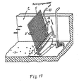
- Figure 17 shows a broken partial representation of a channel with a Sieve 5 made of sieve rods 5 ', which is a reamer in the form of a wide jet nozzle 32 is assigned, which is similar to a reamer with tines parallel to the screen surface of the sieve 5 is guided.
- Both the sieve and the Wide jet nozzle 32 extend over the entire clear width of the Gerinnequeriteses.
- the wide jet nozzle 32 does not require any mechanical means different ways for the up and down movement, a targeted Operation only for detachment and removal of deposits on the sieve Solids towards the bottom can be reached by using the Only spray the spray jet with the downward movement in the course of the downward movement leaves.
- This spray liquid - cleaning water - can e.g. by a hose line 33 or the like can be supplied, but it is also possible, this liquid from the cleaned area behind the Remove sieve 5 from the liquid. For the rest, this representation is rejected to the circumstances according to FIG. 3 and in this context given explanations.
- Figure 18 shows one in this respect for all of the above-described embodiments, that is to say entirely generally applicable configuration of the screen of the computing device in such a way that the through openings are seen from the ground upwards of the sieve for the liquid to be freed from solids are trained.
- a sieve with perforated openings as with a sieve with elongated openings for example and especially in vertical planes, each spaced-apart sieve bars, which in this respect also by corresponding areas of the rake according to FIGS. 11 and 12 can be formed can.
- a sieve is formed using sieve rods, the protruding from the floor of different lengths upwards are trained.
- a lower area of the screen has a number of in Direction of the width of the channel closely spaced rods 5 ', 5 “and 5'", which is therefore proportionate at a lower liquid level close-meshed sieve - sieve with (small) narrow openings - form. Looking up towards a higher water level every second rod ends 5 ", so that between the rods 5 'and 5"' result in wider distances and thus a lower flow resistance. In In a zone which is moved even further up, the rods 5 '' also end, so that a high hydraulic permeability is given. That kind of Sieve design can be used instead of the height-limited design Sieves - Figures 8, 9 and 12 or also in the context of such height-limited training may be provided. Otherwise, the The above-mentioned creation of distances by omitting Bar sections are not mandatory, they can also be offset laterally Rod arrangements are provided and otherwise different thickly formed rod areas.
Landscapes
- Chemical & Material Sciences (AREA)
- Chemical Kinetics & Catalysis (AREA)
- Separation Of Solids By Using Liquids Or Pneumatic Power (AREA)
- Sewage (AREA)
- Filtration Of Liquid (AREA)
- Extraction Or Liquid Replacement (AREA)
Description
- Figur 1
- ein Rechengerät innerhalb eines Gerinnes in teilweise aufgebrochener perspektivischer Darstellung mit einem zum Boden des Gerinnes bündigen Sammelraum, wobei das Sieb als Stabrechen ausgebildet ist und der Räumer mit in Strömungsrichtung abragenden Harkenzinken versehen ist und die Abführung der abgestreiften Feststoffe aus dem Sammelraum durch Unterdruck mittels einer Tauchmotorpumpe erfolgt;
- Figur 2
- ein Rechengerät innerhalb eines Gerinnes in teilweise aufgebrochener Darstellung mit einem als rinnenförmige Aussparung vertieften, in dem Rinnenboden ausgearbeiteten Sammelraum, wobei das Sieb als Stabrechen ausgebildet ist und der Räumer mit in Strömungsrichtung abragenden Harkenzinken versehen ist und die Abführung der abgestreiften Feststoffe aus dem Sammelraum durch Unterdruck mittels einer Tauchmotorpumpe erfolgt;
- Figur 3
- ein Rechengerät innerhalb eines Gerinnes in teilweise aufgebrochener perspektivischer Darstellung mit einem zum Boden des Gerinnes bündigen Sammelraum, wobei das Sieb als Stabrechen ausgebildet ist und der Räumer mit in Gegenströmungsrichtung abragenden Harkenzinken versehen ist und die Abführung der abgestreiften Feststoffe aus dem Sammelraum durch Unterdruck mittels einer Tauchmotorpumpe erfolgt;
- Figur 4
- ein Rechengerät innerhalb eines Gerinnes in teilweise aufgebrochener perspektivischer Darstellung mit einem als rinnenförmige Aussparung vertieften, in dem Rinnenboden ausgearbeiteten Sammelraum, wobei das Sieb als Stabrechen ausgebildet ist und der Räumer mit in Gegenstromrichtung abragenden Harkenzinken versehen ist und die Abführung der abgestreiften Feststoffe aus dem Sammelraum durch Unterdruck mittels einer Tauchmotorpumpe erfolgt;
- Figur 5
- ein Rechengerät und eine Sammelraumausbildung ähnlich Figur 2, wobei anstelle der Tauchmotorpumpe eine außerhalb der Strömung oberhalb der Gerinneoberebene aufgestellte Pumpe vorgesehen ist;
- Figur 6
- ein Rechengerät und eine Sammelraumausbildung ähnlich Figur 2, wobei als Abtransporteinrichtung bzw. Druckerzeugungseinrichtung eine Druckpumpe vorgesehen ist;
- Figur 7
- ein Rechengerät und eine Sammelraumausbildung ähnlich Figur 2, bei der als Abtransportvorrichtung eine aus zwei Abschnitten bestehende Förderschneckenausbildung vorgesehen ist.
- Figur 8
- ein Rechengerät und eine Sammelraumausbildung ähnlich Figur 3 zur Verdeutlichung einer derart niedrigeren Rechenausbildung unterhalb der Oberkante des Gerinnes, so dass ein Notüberlauf ermöglicht ist;
- Figur 9
- ein Rechengerät und eine Sammelraumausbildung ähnlich Figur 2 zur Verdeutlichung einer derart niedrigeren Rechenausbildung unterhalb der Oberkante des Gerinnes, so dass ein Notüberlauf ermöglicht ist;
- Figur 10
- ein Rechengerät in Ausbildung als Lochblechrechen in Anwendung auf eine Sammelraumausbildung gemäß Figur 2;
- Figur 11
- ein Rechengerät in Ausbildung als Paternosterrechen in Anwendung auf eine Sammelraumausbildung gemäß Figur 2;
- Figur 12
- ein Rechengerät in Ausbildung als Filterstufenrechen in Anwendung auf eine Sammelraumausbildung gemäß Figur 2 in einer einen Notüberlauf ermöglichenden Höhenausbildung;
- Figur 13
- ein Rechengerät mit einer Sammelraumausbildung gemäß Figur 3 mit einem Drei-Wege-Schieber in der Abtransportleitung zur wahlweisen Rückführung des abzutransportierenden Feststoffes zur wiederholten Waschung zurück in den Sammelraum;
- Figur 14
- ein Rechengerät in Anwendung auf eine Sammelraumausbildung gemäß Figur 2 mit einer Zerkleinerungsvorrichtung innerhalb des Sammelraumes mit einer Rückspülung von insoweit vorzerkleinertem Feststoff am Ausgang des Zerkleinerers zur Rückführung an dessen Eingang;
- Figur 15
- ein Rechengerät ähnlich Figur 14 mit einer in einem Sammelraum derart angeordneten Zerkleinerungsvorrichtung, dass unter dieser ein Geröllfang gebildet ist;
- Figur 16
- ein Rechengerät in Ausbildung als Siebwendel oder Siebschnecke in Mehrfachanordnung in Anwendung an einem teilweise rinnenförmig unterhalb des Gerinnebodens ragenden Sammelraum und einem DreiWege-Schieber in der Abtransportleitung für die gegebenenfalls wiederholte Rückführung des abzutransportierenden Feststoffes in den Sammelraum.
- Figur 17
- ein Rechengerät ähnlich beispielsweise demgemäss Figuren 3 und 4, bei dem der Räumer anstelle von Harkenzinken mit Spritzdüsen versehen ist, im vorliegenden Beispiel als Breitstrahldüse ausgebildet;
- Figur 18
- ein Rechengerät mit einem als Stabrechen ausgebildeten Sieb mit vom Boden aus gesehen nach oben sich erweiternden Sieböffnungen;
Claims (11)
- Verfahren für das Aussondern von Feststoffen aus einem in einer bestimmten Strömungsrichtung zufließenden Flüssigkeits-Feststoff-Gemisch (Suspension), beispielsweise Abwasser, in einem Gerinne, Behälter oder dergleichen durch Auffangen der Feststoffe an einer das Flüssigkeits-Feststoff-Gemisch quer zu dessen Strömungsrichtung durchgreifenden Siebfläche und deren durch mechanischen Angriff zwangsweiser Abförderung von der Siebfläche zur Weiterbehandlung,
dadurch gekennzeichnet, dass die Abförderung der Feststoffe von der Siebfläche zum Boden des Gerinnes, Behälters oder dergleichen hin durch zum Boden gerichteten mechanischen Angriff zwangsweise erfolgt, worauf im Zuge der Weiterverarbeitung die Feststoffe aus dem Bodenbereich des Gerinnes, Behälters oder dergleichen nach außerhalb der Strömung abtransportiert oder in dem Bodenbereich zerkleinert oder soweit nicht genügend zerkleinert aus dem Bodenbereich nach außerhalb der Strömung abtransportiert werden. - Verfahren nach Anspruch 1,
dadurch gekennzeichnet, dass die Feststoffe im Zuge des Abtransportes dem Bodenbereich wiederholt zugeführt werden. - Trenneinrichtung für das Aussondern von Feststoffen aus einer in einer bestimmten Richtung zufließenden Strömung eines Flüssigkeits-Feststoff-Gemisches (Suspension), beispielsweise Abwasser, in einem Gerinne (2), Behälter oder dergleichen mit einem in das Flüssigkeits-Feststoff-Gemisch dieses quer zu dessen Strömungsrichtung durchgreifend eingesetzten Rechengerät (1), das ein Sieb (4) und einen Räumer (6) umfasst, welch letzterer die von dem Sieb (4) aus dem Gemisch aufgefangenen Feststoffe von diesem abstreift, zur Durchführung des Verfahrens nach Anspruch 1 oder 2,
dadurch gekennzeichnet, dass der Räumer (6) die von dem Sieb (4) abgestreiften Feststoffe in den Bodenbereich des Gerinnes (2), Behälters oder dergleichen hin gerichtet abfördernd ausgebildet ist und dass eine Transportvorrichtung für die Überführung des von dem Räumer (6) zum Bodenbereich abgestreiften Feststoffes nach außerhalb der Strömung vorgesehen ist oder in dem Bodenbereich eine Zerkleinerungsvorrichtung (29) - Häcksel-, Schreddervorrichtung oder ähnliches - für den Weitertransport des entsprechend zerkleinerten, das Sieb (4) passierenden Feststoffes mit dem Flüssigkeitsstrom zu einer Kläranlage oder dergleichen vorgesehen ist oder sowohl eine Zerkleinerungsvorrichtung (29) als auch eine Transportvorrichtung für die Überführung der nicht genügend zerkleinerten Feststoffe nach außerhalb der Strömung vorgesehen sind. - Trennvorrichtung nach Anspruch 3,
dadurch gekennzeichnet, dass der Bodenbereich für die Aufnahme des mittels des Räumers (6) von dem Sieb (4) abgestreiften Feststoffes durch einen Sammelraum (9) gebildet ist, der oberhalb der Sohle (3) des Gerinnes (2) bzw. Bodens des Behälters oder dergleichen oder zumindest teilweise durch eine Ausnehmung (10) unterhalb der Sohle (3) bzw. des Bodens gebildet ist, welcher Sammelraum (9) an die Transportvorrichtung (13; 19; 20) in Ausbildung als Unterdruckquelle wie Saugpumpe (13), im Sinne einer Evakuierung beaufschlagter Unterdruckraum oder dergleichen oder Druckpumpe, im Sinne eines Druckaufbaues beaufschlagter Überdruckraum oder dergleichen oder mechanische Fördervorrichtung wie Förderschnecke oder dergleichen angeschlossen ist. - Trennvorrichtung nach Anspruch 3 oder 4,
dadurch gekennzeichnet, dass das Sieb (4) von seinem unteren Randbereich aus gesehen in oder aus der Vertikalen gegen die Strömungsrichtung geneigt ausgebildet ist. - Trenneinrichtung nach Anspruch 5,
dadurch gekennzeichnet, dass das Sieb (5) in etwa vertikaler Ebene, nach Maßgabe der Siebwirkung beabstandet parallel verlaufend angeordnete Siebstäbe (5') aufweist, zwischen denen die Sieböffnungen als von oben nach unten zum Boden (3) des Gerinnes (2), Behälters oder dergleichen verlaufende Schlitze ausgebildet sind, in die Harkenzinken (7) des Räumers (6) im Zuge der Abstreifbewegung von oben nach unten eingreifen, während die entgegengesetzte Bewegung der Harkenzinken (7) außerhalb des Eingriffes an dem Sieb (5) erfolgt, wobei die Harkenzinken (7) in Strömungsrichtung abragend oder entgegengesetzt in die Sieböffnungen eingreifend ausgebildet sind. - Trenneinrichtung nach einem der Ansprüche 3 bis 5,
dadurch gekennzeichnet, dass das Sieb als Lochblech (23) ausgebildet ist, an dem der Räumer (24) schiebend oder rotierend von oben nach unten entlanggeführt ist, während die entgegengesetzte Bewegung außerhalb des Angriffs an dem Sieb erfolgt. - Trenneinrichtung nach einem der Ansprüche 3 bis 5,
dadurch gekennzeichnet, dass das Rechengerät als Paternosterrechen (25) oder Filterstufenrechen (26) ausgebildet Ist. - Trenneinrichtung nach Anspruch 3 oder 4,
dadurch gekennzeichnet, dass das Rechengerät als eine oder mehrere nebeneinander angeordneten Siebwendel - oder Siebspiralrechenvorrichtungen (31) ausgebildet ist oder sind. - Trenneinrichtung nach einem der Ansprüche 3 bis 5,
dadurch gekennzeichnet, dass der Räumer durch auf die an dem Sieb (5) aufgefangenen Feststoffe gerichtete Spritzdüsen gebildet ist, die in Höhenrichtung des Siebes verschiebbar sind. - Trenneinrichtung nach einem der Ansprüche Anspruch 3 bis 10,
dadurch gekennzeichnet, dass die Öffnungen des Siebes (5) vom Boden aus gesehen nach oben zunehmend größer (weiter) ausgebildet sind, insbesondere bei Ausbildung mit Siebstäben (5', 5", 5''') derart, dass deren Beabstandung - vorzugsweise gestuft - nach oben hin größer werdend ausgebildet ist.
Applications Claiming Priority (3)
| Application Number | Priority Date | Filing Date | Title |
|---|---|---|---|
| DE19907067A DE19907067C2 (de) | 1999-02-19 | 1999-02-19 | Trennvorrichtung für das Aussondern von Feststoffen aus einem Flüssigkeits-Feststoff-Gemisch |
| DE19907067 | 1999-02-19 | ||
| PCT/DE2000/000496 WO2000048705A1 (de) | 1999-02-19 | 2000-02-21 | Trenneinrichtung für das aussondern von feststoffen aus einem flüssigkeits- feststoff- gemisch |
Publications (2)
| Publication Number | Publication Date |
|---|---|
| EP1161292A1 EP1161292A1 (de) | 2001-12-12 |
| EP1161292B1 true EP1161292B1 (de) | 2003-05-02 |
Family
ID=7898090
Family Applications (1)
| Application Number | Title | Priority Date | Filing Date |
|---|---|---|---|
| EP00910549A Expired - Lifetime EP1161292B1 (de) | 1999-02-19 | 2000-02-21 | Trenneinrichtung für das aussondern von feststoffen aus einem flüssigkeits- feststoff- gemisch |
Country Status (4)
| Country | Link |
|---|---|
| EP (1) | EP1161292B1 (de) |
| AT (1) | ATE238833T1 (de) |
| DE (2) | DE19907067C2 (de) |
| WO (1) | WO2000048705A1 (de) |
Cited By (3)
| Publication number | Priority date | Publication date | Assignee | Title |
|---|---|---|---|---|
| DE102014103865A1 (de) | 2014-03-20 | 2015-10-08 | Rudolf Bischof Gmbh Technische Handelsvertretungen | Verfahren und Vorrichtung zum Verändern eines Pegelstands sowie Verwendungen derselben bei der Trennung von Feststoffen zu Flüssigkeiten |
| DE102016110760A1 (de) | 2016-05-27 | 2017-11-30 | Rudolf Bischof Gmbh | Pegelstandseinstellungsvorrichtung sowie damit versehene Flüssigkeits-Feststoff-Trennvorrichtung |
| EP4178917A4 (de) * | 2020-07-10 | 2024-07-03 | Jets AS | Abscheider für ein abwassersystem |
Families Citing this family (15)
| Publication number | Priority date | Publication date | Assignee | Title |
|---|---|---|---|---|
| EP1222950A1 (de) * | 2001-01-16 | 2002-07-17 | Ludwig Kaminski | Vorrichtung zum Trennen von durch Fräs- oder Schneidvorgänge erzeugten Flüssigkeiten |
| AUPR533301A0 (en) * | 2001-05-29 | 2001-06-21 | Wallace & Sons Research Pty Ltd | Pump assembly |
| DE102005010576A1 (de) * | 2005-03-04 | 2006-09-14 | Gesellschaft für Planung, Maschinen- und Mühlenbau Erhard Muhr mbH | Rechenanlage mit anpreßbarer Reinigungsharke |
| DE102007035081A1 (de) | 2007-04-18 | 2008-10-23 | Rudolf Bischof Gmbh Technische Handelsvertretungen | Siebrechenvorrichtung sowie Verwendungen davon |
| US9707496B2 (en) * | 2009-09-02 | 2017-07-18 | Terry L. Duperon | Thin plate apparatus for removing debris from water |
| DE102011082629B4 (de) | 2011-09-13 | 2015-07-23 | Rudolf Bischof GmbH Technische HV Abwassertechnik | Siebrechenvorrichtung |
| US9962740B2 (en) * | 2015-03-25 | 2018-05-08 | Ruggenthaler Manufacturing, LLC | Self-actuating debris removal device |
| DE102016103081A1 (de) * | 2016-02-23 | 2017-08-24 | Huber Se | Siebvorrichtung |
| CN107989158B (zh) * | 2017-12-26 | 2020-04-14 | 陕西一和环境工程有限公司 | 易清理排污渠 |
| FI128183B (en) * | 2018-04-04 | 2019-12-13 | Jouni Salonen | Biowaste collection system and an intermediate tank for a biowaste collection system |
| CN112121491A (zh) * | 2020-09-25 | 2020-12-25 | 申阳 | 一种废水处理装置 |
| ES2909464B2 (es) * | 2020-11-05 | 2023-02-20 | Deyma La Mancha S L | Dispositivo de desbaste en pozos de gruesos, de una estación depuradora de aguas residuales |
| CN113559610B (zh) * | 2021-07-19 | 2022-07-05 | 宜兴泉溪环保设备有限公司 | 一种方便清理的城市污水处理用格栅结构 |
| CN114177677B (zh) * | 2021-12-20 | 2022-06-24 | 河津市炬华铝业有限公司 | 一种活性氧化铝生产用压滤装置及其压滤方法 |
| CN115228782B (zh) * | 2022-07-25 | 2023-09-22 | 湘西土家族苗族自治州畜牧水产事务中心 | 一种稻田养鱼的拦鱼装置及其工作方法 |
Family Cites Families (9)
| Publication number | Priority date | Publication date | Assignee | Title |
|---|---|---|---|---|
| US2672985A (en) * | 1950-08-14 | 1954-03-23 | Louise N Millspaugh | Transfer and comminuting device for screens |
| US3836463A (en) * | 1972-07-28 | 1974-09-17 | Gen Signal Corp | System and apparatus for cleaning bar grid |
| SE416413B (sv) * | 1978-02-10 | 1980-12-22 | Hans Hansson | Anordnig for automatisk resning av avskiljningsgaller vid turbinintag, friskvattenintag,avloppsanleggning och liknande |
| US4792394A (en) * | 1985-10-04 | 1988-12-20 | Rudz Enterprises, Inc. | Bar screening apparatus |
| DE3624523A1 (de) * | 1986-07-19 | 1988-01-21 | Holstein & Kappert Maschf | Vorrichtung zum filtern der spritzfluessigkeit in reinigungsmaschinen |
| DE3913020A1 (de) * | 1989-04-20 | 1990-10-25 | Passavant Werke | Rechenreinigungsvorrichtung |
| DE4320678C2 (de) * | 1993-06-22 | 1996-04-11 | Branko Dipl Ing Klasnic | Vorrichtung zum Entfernen von Rechengut aus einer mit einer verunreinigten Flüssigkeit durchströmten Zulaufrinne, insbesondere von Kläranlagen |
| DE4328476C2 (de) * | 1993-08-24 | 1997-10-30 | Rudolf Bischof Gmbh Tech Hande | Vorrichtung zum Austragen von festen Bestandteilen aus einem Fluid |
| DE4429537C2 (de) * | 1994-08-19 | 1998-09-17 | Durchschlag & Bever Gmbh | Abwasserreinigungsanlage |
-
1999
- 1999-02-19 DE DE19907067A patent/DE19907067C2/de not_active Expired - Fee Related
-
2000
- 2000-02-21 DE DE50001965T patent/DE50001965D1/de not_active Expired - Fee Related
- 2000-02-21 AT AT00910549T patent/ATE238833T1/de not_active IP Right Cessation
- 2000-02-21 EP EP00910549A patent/EP1161292B1/de not_active Expired - Lifetime
- 2000-02-21 WO PCT/DE2000/000496 patent/WO2000048705A1/de not_active Ceased
Cited By (6)
| Publication number | Priority date | Publication date | Assignee | Title |
|---|---|---|---|---|
| DE102014103865A1 (de) | 2014-03-20 | 2015-10-08 | Rudolf Bischof Gmbh Technische Handelsvertretungen | Verfahren und Vorrichtung zum Verändern eines Pegelstands sowie Verwendungen derselben bei der Trennung von Feststoffen zu Flüssigkeiten |
| EP2933391A1 (de) | 2014-03-20 | 2015-10-21 | Rudolf Bischof GmbH Technische Handelsvertretung Abwassertechnik | Verfahren und Vorrichtung zum Verändern eines Pegelstands sowie Verwendungen derselben bei der Trennung von Feststoffen von Flüssigkeiten |
| DE102014103865B4 (de) * | 2014-03-20 | 2018-02-01 | Rudolf Bischof Gmbh Technische Handelsvertretungen | Verfahren und Vorrichtung zum Verändern eines Pegelstands sowie Verwendungen derselben bei der Trennung von Feststoffen von Flüssigkeiten |
| DE102016110760A1 (de) | 2016-05-27 | 2017-11-30 | Rudolf Bischof Gmbh | Pegelstandseinstellungsvorrichtung sowie damit versehene Flüssigkeits-Feststoff-Trennvorrichtung |
| DE102016110760B4 (de) | 2016-05-27 | 2019-09-26 | Rudolf Bischof Gmbh | Pegelstandseinstellungsvorrichtung sowie damit versehene Flüssigkeits-Feststoff-Trennvorrichtung |
| EP4178917A4 (de) * | 2020-07-10 | 2024-07-03 | Jets AS | Abscheider für ein abwassersystem |
Also Published As
| Publication number | Publication date |
|---|---|
| DE19907067C2 (de) | 2001-05-10 |
| EP1161292A1 (de) | 2001-12-12 |
| DE50001965D1 (de) | 2003-06-05 |
| DE19907067A1 (de) | 2000-09-14 |
| ATE238833T1 (de) | 2003-05-15 |
| WO2000048705A1 (de) | 2000-08-24 |
Similar Documents
| Publication | Publication Date | Title |
|---|---|---|
| EP1161292B1 (de) | Trenneinrichtung für das aussondern von feststoffen aus einem flüssigkeits- feststoff- gemisch | |
| DE69713741T2 (de) | Sediment- und abfallabscheider für regenwasser | |
| DE69115490T2 (de) | Entwässerungssystem zum entfernen von schlamm | |
| DE2362674A1 (de) | Vorrichtung zum abtrennen der festen und der fluessigen bestandteile aus einer schlamm fuehrenden fluessigkeit | |
| DD229452A5 (de) | Verfahren und vorrichtung zur aufbereitung einer dickspuelung | |
| DE4211657C1 (de) | ||
| EP0654294A2 (de) | Verfahren und Vorrichtung zum Ausfiltrieren und Rückspülen von Feststoff-Partikeln aus Flüssigkeiten | |
| DE69313682T2 (de) | Reinigungsvorrichtung | |
| DE3122131C2 (de) | Vorrichtung zur Entnahme und Entwässerung von Feststoffen aus Flüssigkeiten, insbesondere aus Gerinnen von Kläranlagen | |
| EP2500459B2 (de) | Verfahren und Vorrichtung zum Waschen von insbesondere Wäschestücken | |
| EP2427310B2 (de) | Verfahren und vorrichtung zum aufbereiten verunreinigter kunststoffgebinde, insbesondere ölbehälter | |
| DE102007035081A1 (de) | Siebrechenvorrichtung sowie Verwendungen davon | |
| DE1658063A1 (de) | Feststoffabfangeinrichtung | |
| DE69216813T2 (de) | Filtrationsanlage für Luftbehandlungsysteme oder Küchenhauben | |
| DE10200599B4 (de) | Vorrichtung zum Abscheiden von organischem und anorganischem Material aus einer Flüssigkeit | |
| EP1291059B1 (de) | Vorrichtung zum Separieren und Austragen von Spänen | |
| EP0672801B1 (de) | Siebelement, Entwässerungsmulde sowie Strassen- und Kanalreinigungsfahrzeug mit einem derartigen Siebelement | |
| WO1995019212A1 (de) | Vorrichtung zur reinigung von in abwassern enthaltenen feststoffen | |
| AT405278B (de) | Kombinierte vorrichtung zum abscheiden von feststoffen und fetten | |
| DE3302490C2 (de) | Sinkscheider | |
| DE20114853U1 (de) | Vorrichtung zum Separieren und Austragen von Spänen | |
| AT520238B1 (de) | Spaltsieb | |
| DE102017201768B3 (de) | Vorrichtung und Verfahren zum Reinigen und Entsteinen von Rodungsfrüchten sowie Verwendung einer solchen Vorrichtung | |
| DE102006013256B4 (de) | Vorrichtung und Verfahren zum Entfernen von Partikeln aus einer Flüssigkeit | |
| EP1286740A1 (de) | Verfahren bzw. einrichtung zum sedimentationstrennen physikalisch detektierbarer partikel aus einem partikelstrom |
Legal Events
| Date | Code | Title | Description |
|---|---|---|---|
| PUAI | Public reference made under article 153(3) epc to a published international application that has entered the european phase |
Free format text: ORIGINAL CODE: 0009012 |
|
| 17P | Request for examination filed |
Effective date: 20010917 |
|
| AK | Designated contracting states |
Kind code of ref document: A1 Designated state(s): AT BE CH CY DE DK ES FI FR GB GR IE IT LI LU MC NL PT SE |
|
| GRAH | Despatch of communication of intention to grant a patent |
Free format text: ORIGINAL CODE: EPIDOS IGRA |
|
| GRAH | Despatch of communication of intention to grant a patent |
Free format text: ORIGINAL CODE: EPIDOS IGRA |
|
| GRAA | (expected) grant |
Free format text: ORIGINAL CODE: 0009210 |
|
| AK | Designated contracting states |
Designated state(s): AT DE FR GB IT NL |
|
| PG25 | Lapsed in a contracting state [announced via postgrant information from national office to epo] |
Ref country code: NL Free format text: LAPSE BECAUSE OF FAILURE TO SUBMIT A TRANSLATION OF THE DESCRIPTION OR TO PAY THE FEE WITHIN THE PRESCRIBED TIME-LIMIT Effective date: 20030502 Ref country code: IT Free format text: LAPSE BECAUSE OF FAILURE TO SUBMIT A TRANSLATION OF THE DESCRIPTION OR TO PAY THE FEE WITHIN THE PRESCRIBED TIME-LIMIT;WARNING: LAPSES OF ITALIAN PATENTS WITH EFFECTIVE DATE BEFORE 2007 MAY HAVE OCCURRED AT ANY TIME BEFORE 2007. THE CORRECT EFFECTIVE DATE MAY BE DIFFERENT FROM THE ONE RECORDED. Effective date: 20030502 Ref country code: GB Free format text: LAPSE BECAUSE OF FAILURE TO SUBMIT A TRANSLATION OF THE DESCRIPTION OR TO PAY THE FEE WITHIN THE PRESCRIBED TIME-LIMIT Effective date: 20030502 Ref country code: FR Free format text: LAPSE BECAUSE OF FAILURE TO SUBMIT A TRANSLATION OF THE DESCRIPTION OR TO PAY THE FEE WITHIN THE PRESCRIBED TIME-LIMIT Effective date: 20030502 |
|
| REG | Reference to a national code |
Ref country code: GB Ref legal event code: FG4D Free format text: NOT ENGLISH |
|
| REF | Corresponds to: |
Ref document number: 50001965 Country of ref document: DE Date of ref document: 20030605 Kind code of ref document: P |
|
| REG | Reference to a national code |
Ref country code: IE Ref legal event code: FG4D Free format text: GERMAN |
|
| NLV1 | Nl: lapsed or annulled due to failure to fulfill the requirements of art. 29p and 29m of the patents act | ||
| GBV | Gb: ep patent (uk) treated as always having been void in accordance with gb section 77(7)/1977 [no translation filed] |
Effective date: 20030502 |
|
| REG | Reference to a national code |
Ref country code: IE Ref legal event code: FD4D Ref document number: 1161292E Country of ref document: IE |
|
| PG25 | Lapsed in a contracting state [announced via postgrant information from national office to epo] |
Ref country code: AT Free format text: LAPSE BECAUSE OF NON-PAYMENT OF DUE FEES Effective date: 20040221 |
|
| PGFP | Annual fee paid to national office [announced via postgrant information from national office to epo] |
Ref country code: DE Payment date: 20040227 Year of fee payment: 5 |
|
| PLBE | No opposition filed within time limit |
Free format text: ORIGINAL CODE: 0009261 |
|
| STAA | Information on the status of an ep patent application or granted ep patent |
Free format text: STATUS: NO OPPOSITION FILED WITHIN TIME LIMIT |
|
| 26N | No opposition filed |
Effective date: 20040203 |
|
| EN | Fr: translation not filed | ||
| PG25 | Lapsed in a contracting state [announced via postgrant information from national office to epo] |
Ref country code: DE Free format text: LAPSE BECAUSE OF NON-PAYMENT OF DUE FEES Effective date: 20050901 |