EP1162007B1 - Bremsrolle für Metallbandspaltanlagen - Google Patents
Bremsrolle für Metallbandspaltanlagen Download PDFInfo
- Publication number
- EP1162007B1 EP1162007B1 EP01201970A EP01201970A EP1162007B1 EP 1162007 B1 EP1162007 B1 EP 1162007B1 EP 01201970 A EP01201970 A EP 01201970A EP 01201970 A EP01201970 A EP 01201970A EP 1162007 B1 EP1162007 B1 EP 1162007B1
- Authority
- EP
- European Patent Office
- Prior art keywords
- braking roller
- braking
- strips
- roller according
- roller
- Prior art date
- Legal status (The legal status is an assumption and is not a legal conclusion. Google has not performed a legal analysis and makes no representation as to the accuracy of the status listed.)
- Expired - Lifetime
Links
Images


Classifications
-
- B—PERFORMING OPERATIONS; TRANSPORTING
- B21—MECHANICAL METAL-WORKING WITHOUT ESSENTIALLY REMOVING MATERIAL; PUNCHING METAL
- B21C—MANUFACTURE OF METAL SHEETS, WIRE, RODS, TUBES, PROFILES OR LIKE SEMI-MANUFACTURED PRODUCTS OTHERWISE THAN BY ROLLING; AUXILIARY OPERATIONS USED IN CONNECTION WITH METAL-WORKING WITHOUT ESSENTIALLY REMOVING MATERIAL
- B21C47/00—Winding-up, coiling or winding-off metal wire, metal band or other flexible metal material characterised by features relevant to metal processing only
- B21C47/003—Regulation of tension or speed; Braking
-
- B—PERFORMING OPERATIONS; TRANSPORTING
- B21—MECHANICAL METAL-WORKING WITHOUT ESSENTIALLY REMOVING MATERIAL; PUNCHING METAL
- B21C—MANUFACTURE OF METAL SHEETS, WIRE, RODS, TUBES, PROFILES OR LIKE SEMI-MANUFACTURED PRODUCTS OTHERWISE THAN BY ROLLING; AUXILIARY OPERATIONS USED IN CONNECTION WITH METAL-WORKING WITHOUT ESSENTIALLY REMOVING MATERIAL
- B21C47/00—Winding-up, coiling or winding-off metal wire, metal band or other flexible metal material characterised by features relevant to metal processing only
- B21C47/006—Winding-up, coiling or winding-off metal wire, metal band or other flexible metal material characterised by features relevant to metal processing only winding-up or winding-off several parallel metal bands
-
- B—PERFORMING OPERATIONS; TRANSPORTING
- B65—CONVEYING; PACKING; STORING; HANDLING THIN OR FILAMENTARY MATERIAL
- B65H—HANDLING THIN OR FILAMENTARY MATERIAL, e.g. SHEETS, WEBS, CABLES
- B65H23/00—Registering, tensioning, smoothing or guiding webs
- B65H23/04—Registering, tensioning, smoothing or guiding webs longitudinally
- B65H23/06—Registering, tensioning, smoothing or guiding webs longitudinally by retarding devices, e.g. acting on web-roll spindle
- B65H23/10—Registering, tensioning, smoothing or guiding webs longitudinally by retarding devices, e.g. acting on web-roll spindle acting on running web
- B65H23/14—Tensioning rollers applying braking forces
-
- B—PERFORMING OPERATIONS; TRANSPORTING
- B65—CONVEYING; PACKING; STORING; HANDLING THIN OR FILAMENTARY MATERIAL
- B65H—HANDLING THIN OR FILAMENTARY MATERIAL, e.g. SHEETS, WEBS, CABLES
- B65H27/00—Special constructions, e.g. surface features, of feed or guide rollers for webs
-
- B—PERFORMING OPERATIONS; TRANSPORTING
- B65—CONVEYING; PACKING; STORING; HANDLING THIN OR FILAMENTARY MATERIAL
- B65H—HANDLING THIN OR FILAMENTARY MATERIAL, e.g. SHEETS, WEBS, CABLES
- B65H2301/00—Handling processes for sheets or webs
- B65H2301/40—Type of handling process
- B65H2301/41—Winding, unwinding
- B65H2301/414—Winding
- B65H2301/4148—Winding slitting
-
- Y—GENERAL TAGGING OF NEW TECHNOLOGICAL DEVELOPMENTS; GENERAL TAGGING OF CROSS-SECTIONAL TECHNOLOGIES SPANNING OVER SEVERAL SECTIONS OF THE IPC; TECHNICAL SUBJECTS COVERED BY FORMER USPC CROSS-REFERENCE ART COLLECTIONS [XRACs] AND DIGESTS
- Y10—TECHNICAL SUBJECTS COVERED BY FORMER USPC
- Y10T—TECHNICAL SUBJECTS COVERED BY FORMER US CLASSIFICATION
- Y10T29/00—Metal working
- Y10T29/49—Method of mechanical manufacture
- Y10T29/49544—Roller making
- Y10T29/49547—Assembling preformed components
- Y10T29/49556—Work contacting surface element assembled to end support members
Definitions
- the present invention relates to a braking roller for systems for cutting metal bands into strips.
- a braking system of the same strips is provided before their winding into single rolls.
- the braking system that is part of the system itself must guarantee a correct and even winding tension of the single strips. In fact, it must be possible to compensate the difference of speed that generates after possible differences of thickness between a strip and the other, since the transversal section of the initial band may not have an even thickness. In fact, it may be thinner at the longitudinal side edges with central swelling, or it may be thinner centrally starting from the thicker longitudinal edges.
- felt elements used as braking system are known, guided into containment housings, that are determined in engagement on the strips of the passing band through an underlying inflatable thrust element.
- the rubber surface of braking rollers - called “presser rollers” - acting on the band strips has also been provided with a series of surface peripheral notches, transversal to the roller axis, thus creating a series of rubber teeth that may allow some possibilities of bending in the advancement direction of the strip, or in the opposite direction.
- Such "folding" or “yielding” surface tooth should facilitate the adaptation to the speed of the single strip of the braking roller. In this way, there would be a suitable differentiated braking on the associated strips cut from the band.
- US-A-4 347 962 discloses a braking roller according to the preamble of claim 1.
- Purpose of the present invention is therefore that of realising a braking roller, called “presser roller”, for systems for cutting metal bands into strips, which should solve the above technical problems.
- Another purpose is that of eliminating any possible difficulty of braking even in the presence of strong variations between the speeds of the different strips obtained from the cutting.
- Another purpose is that of eliminating any possible defect that may arise on the surface of the strips due to the braking, so as to protect the surfaces of the same strips.
- Another purpose is that of realising a braking roller for systems for cutting metal bands into strips that should be little expensive and easy to manufacture and operate, without problems of continuous adjustment or setting interventions.
- Figure 1 shows a system wherein a roll of band 12, once cut through a special shear 13, generates a certain number of strips 14, which must then be wound into final rolls 15 through a special winding reel. Braking rollers, as well as a compensation area, are provided between shear 13 and the winding reel so as to facilitate such operation.
- Figure 1 shows how it is possible to provide, in the braking units, drafting elements consisting of one or two "braking rollers", or braking rollers 16 according to the invention, in collaboration with baffle rollers 18 and simple tows 19.
- Figure 2 shows how braking rollers according to the invention can be used as baffle rollers 18 or as braking bridles 17, thus solving the problems of known braking rollers of the prior art.
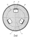
- Figures 3 and 4 respectively show a front partly sectioned view of a braking roller and an enlarged transversal section of the same braking roller that in general can be used for systems for cutting metal bands into strips.
- a braking roller 16, 17, 18 has been devised as braking element for "slitter" systems in general; that is to say that it can be used as component of one or more tangential braking tows, as component of one or more braking bridles, or simply as baffle roller, in the schematic system shown in figures 1 and 2.
- a braking roller 16, 17, 18 consists of a series of elements combined in a particular manner.
- a shaft 20 is provided, towed into rotation by a motor, schematised in 21, which is thus rotating, that forms the carrying structure.
- Shaft 20 is provided with two end pins 22 and 23 adapted to receive support bearings, schematised in 33, of the same roller and on one side, it connects to the above motorisation unit.
- the idle pulleys 25 can freely rotate without any axial movement, and they can be externally provided with a covering 28, made of a scratch-proof engagement material of various types, such as for example rubber material, leather, spunbonded fabric, etc.
- the inflatable elements 29, such as air tubes or the like, are fed from the outside with pressurised air through a pipe 31 connected to a rotating joint, schematised in 32, fastened to the other end of shaft 20.
- the pressure into the inflatable elements 29 can be regulated in function of the particular requirements from the outside, in a quick and simple manner, even during the operation of the braking roller into the system.
- one or n wear elements 34 are provided, one for each inflatable element 29, arranged into recesses 30 and such as to fill them with the inflatable element 29, so as to try to protrude inwards of each idle pulley 25.
- the wear element 34 is made by the inflatable element 29 to abut against the inside surface of each idle pulley 25.
- These wear elements 34 can be made of various types of material, for example felt, brake lining, etc., and they can be easily replaced by side extraction through suitable slits 35 obtained on the side containment flanges 27. In case of bad operation, it is even possible to replace the inflatable elements 29.
- the operating principle of the braking roller 16, 17, 18 of the present invention is as follows: the roller is put into rotation by motor 21 connected to shaft 20 so that the peripheral speed corresponding to the outside surface of pulleys 25, or of covering 28, is slightly less than the speed of the slowest strip 14 of band 12.
- each pulley 25, pulled by strip 14 into contact with it rotates - with respect to shaft 20 - at a slightly higher speed than the difference between its speed and the speed of the slowest strip.
- the presence of the pulleys, of the covering of the same, if present, and of the inflatable element and of the wear element allows the adjustment to the different speeds of the strips of the single portion of the braking roller in a functional, correct and practical manner. In fact, it is possible to guarantee a correct and even winding tension of the single strips, thus compensating the difference of speed that generates after possible differences of thickness between the strips.
- the presence of the pulleys, of the inflatable element and of the wear element, as well as of the pulley covering, allows a suitable adjustment.
Landscapes
- Engineering & Computer Science (AREA)
- Mechanical Engineering (AREA)
- Rolls And Other Rotary Bodies (AREA)
- Accessories And Tools For Shearing Machines (AREA)
- Controlling Rewinding, Feeding, Winding, Or Abnormalities Of Webs (AREA)
- Braking Arrangements (AREA)
- Winding, Rewinding, Material Storage Devices (AREA)
- Registering, Tensioning, Guiding Webs, And Rollers Therefor (AREA)
- Advancing Webs (AREA)
Claims (8)
- Bremsrolle für Systeme, um Metallbänder in Streifen zu schneiden, mit einer rotierenden und motorisierten (21) Welle (20), die zwei (in 33) lagerbare Endzapfen (22, 23) aufweist und an einer zentralen Seitenfläche (24) eine Serie von losen Rollen (25) trägt, die axial (in 27) gehalten sind, wobei in der zentralen Seitenfläche (24) zumindest eine Ausnehmung (30) vorgesehen ist, in der zumindest ein aufblasbares Element (29) angeordnet ist, über dem zumindest ein Verschleißelement (34) angeordnet ist, das so ausgebildet ist, dass es einwärts von jeder losen Rolle (25) anliegt, wobei die Serie von losen Rollen (25) durch zwei seitliche Aufnahmeflansche (27) axial gehalten wird, die ihre relative Drehung zulassen,
dadurch gekennzeichnet, dass zumindest einer der beiden seitlichen Aufnahmeflansche (27) zumindest einen Schlitz (35) für die Entnahme und/oder das Einsetzen des zumindest einen Verschleißelements (34) aufweist. - Bremsrolle nach Anspruch 1,
dadurch gekennzeichnet, dass das zumindest eine aufblasbare Element (29) von der Außenseite über Druckluft durch ein Rohr (31), das mit einer Drehkupplung (32) verbunden ist, die an einem Endzapfen (23) der Welle (20) angebracht ist, gespeist werden kann. - Bremsrolle nach Anspruch 1,
dadurch gekennzeichnet, dass jedes der Serie von losen Rollen (25) mit einer Abdeckung (28) versehen ist, die aus einem kratzfesten Eingriffsmaterial besteht. - Bremsrolle nach Anspruch 3,
dadurch gekennzeichnet, dass das kratzfeste Eingriffsmaterial ein Gummimaterial, Leder oder ein Spinnvlies ist. - Bremsrolle nach Anspruch 1,
dadurch gekennzeichnet, dass der zumindest eine der beiden seitlichen Aufnahmeflansche (27) zumindest einen Schlitz (35) für die Entnahme und/oder das Einsetzen des zumindest einen aufblasbaren Elements (29) aufweist. - Bremsrolle nach Anspruch 1,
dadurch gekennzeichnet, dass die Welle (20) mit einem Motor (21) versehen ist, der mit einem (22) der beiden Endzapfen (22, 23) verbunden ist. - Bremsrolle nach Anspruch 1,
dadurch gekennzeichnet, dass das zumindest eine Verschleißelement (34) aus Filz oder Bremsbelag besteht. - Bremsrolle nach Anspruch 1,
dadurch gekennzeichnet, dass das zumindest eine aufblasbare Element (29) aus zumindest einem Luftschlauch besteht.
Applications Claiming Priority (2)
| Application Number | Priority Date | Filing Date | Title |
|---|---|---|---|
| ITMI201208 | 2000-05-31 | ||
| IT2000MI001208A IT1317956B1 (it) | 2000-05-31 | 2000-05-31 | Rullo di frenatura per impianti di taglio di nastri metallici instrisce. |
Publications (2)
| Publication Number | Publication Date |
|---|---|
| EP1162007A1 EP1162007A1 (de) | 2001-12-12 |
| EP1162007B1 true EP1162007B1 (de) | 2004-06-16 |
Family
ID=11445159
Family Applications (1)
| Application Number | Title | Priority Date | Filing Date |
|---|---|---|---|
| EP01201970A Expired - Lifetime EP1162007B1 (de) | 2000-05-31 | 2001-05-25 | Bremsrolle für Metallbandspaltanlagen |
Country Status (7)
| Country | Link |
|---|---|
| US (1) | US6599224B2 (de) |
| EP (1) | EP1162007B1 (de) |
| CN (1) | CN1213818C (de) |
| AT (1) | ATE269176T1 (de) |
| DE (1) | DE60103811T2 (de) |
| ES (1) | ES2223729T3 (de) |
| IT (1) | IT1317956B1 (de) |
Families Citing this family (12)
| Publication number | Priority date | Publication date | Assignee | Title |
|---|---|---|---|---|
| US20040051948A1 (en) * | 2002-09-11 | 2004-03-18 | David Reed | Systems, methods, and apparatus for patterned sheeting |
| US6964392B1 (en) * | 2003-06-24 | 2005-11-15 | Matsunaga Douglas S | Variable strip tensioner |
| US8191340B1 (en) * | 2008-12-11 | 2012-06-05 | Cp Packaging, Inc. | Mandrel brake arrangement for a web supply in a packaging machine |
| JP5565889B1 (ja) * | 2013-02-06 | 2014-08-06 | Jdc株式会社 | サクションロール装置 |
| CN105179527B (zh) * | 2015-10-21 | 2017-09-22 | 湖南远扬煤机制造有限公司 | 一种多段圆辊式盘形闸及单级软启动无级调速箱 |
| EP3251989B1 (de) * | 2016-05-30 | 2019-05-08 | OCE Holding B.V. | Bahnwicklung mit reibungsbedingter anspannung |
| DE202017105245U1 (de) | 2017-07-12 | 2018-10-16 | Danieli Germany GmbH | Bremsrolle und Bremsrollensystem zum Spannen von Bandstreifen aus Metall |
| DE102017120012B4 (de) | 2017-07-12 | 2024-07-11 | Danieli Germany GmbH | Bremsrolle und Bremsrollensystem zum Spannen von Bandstreifen aus Metall |
| CN109132666A (zh) * | 2018-07-13 | 2019-01-04 | 佛山市百明实业有限公司 | 一种钢带自动调整装置 |
| CN109333066B (zh) * | 2018-09-27 | 2020-07-17 | 浙江花园铜业有限公司 | 一种铜带挤压装置及挤压方法 |
| CN110422672B (zh) * | 2019-09-04 | 2020-11-13 | 浙江聚众柔印科技有限公司 | 一种气动防打滑的印刷机用导送装置 |
| WO2023219563A2 (en) * | 2022-05-13 | 2023-11-16 | National University Of Singapore | Force control module and wearable device comprising the same |
Family Cites Families (9)
| Publication number | Priority date | Publication date | Assignee | Title |
|---|---|---|---|---|
| FR94782E (fr) | 1966-09-20 | 1969-11-21 | Creil Const Mec | Perfectionnements apportés a l'enroulement sur un meme mandrin d'une pluralité de bandes. |
| FR2029280A6 (de) * | 1969-01-23 | 1970-10-16 | Comec Creil Const Meca | |
| FR2079762A5 (de) | 1970-02-12 | 1971-11-12 | Plantard Bernard | |
| US3685711A (en) * | 1970-09-08 | 1972-08-22 | Forges De La Loire Comp D Atel | Tension adjuster for slit metal sheets |
| US4026491A (en) | 1975-12-31 | 1977-05-31 | Theodore Bostroem | Winder drums for strip slitting lines |
| US4120576A (en) * | 1977-04-04 | 1978-10-17 | Xerox Corporation | Drum support apparatus |
| DE2933775C2 (de) | 1979-08-21 | 1981-11-05 | Sundwiger Eisenhütte Maschinenfabrik Grah & Co, 5870 Hemer | Bremsrolle zum Spannen von mehreren Bändern |
| JP2651891B2 (ja) | 1993-11-05 | 1997-09-10 | 株式会社日本開発コンサルタント | 円形型金属性帯板張力付与装置 |
| US6440048B1 (en) * | 1998-12-31 | 2002-08-27 | Eastman Kodak Company | Low cost fuser rollers |
-
2000
- 2000-05-31 IT IT2000MI001208A patent/IT1317956B1/it active
-
2001
- 2001-05-24 US US09/864,933 patent/US6599224B2/en not_active Expired - Fee Related
- 2001-05-25 EP EP01201970A patent/EP1162007B1/de not_active Expired - Lifetime
- 2001-05-25 DE DE60103811T patent/DE60103811T2/de not_active Expired - Fee Related
- 2001-05-25 AT AT01201970T patent/ATE269176T1/de not_active IP Right Cessation
- 2001-05-25 ES ES01201970T patent/ES2223729T3/es not_active Expired - Lifetime
- 2001-05-31 CN CNB011213140A patent/CN1213818C/zh not_active Expired - Fee Related
Also Published As
| Publication number | Publication date |
|---|---|
| US20020006854A1 (en) | 2002-01-17 |
| EP1162007A1 (de) | 2001-12-12 |
| ITMI20001208A0 (it) | 2000-05-31 |
| ITMI20001208A1 (it) | 2001-12-01 |
| US6599224B2 (en) | 2003-07-29 |
| ES2223729T3 (es) | 2005-03-01 |
| CN1213818C (zh) | 2005-08-10 |
| IT1317956B1 (it) | 2003-07-21 |
| DE60103811D1 (de) | 2004-07-22 |
| CN1325770A (zh) | 2001-12-12 |
| ATE269176T1 (de) | 2004-07-15 |
| DE60103811T2 (de) | 2005-07-28 |
Similar Documents
| Publication | Publication Date | Title |
|---|---|---|
| EP1162007B1 (de) | Bremsrolle für Metallbandspaltanlagen | |
| US4480801A (en) | Webbing system | |
| DE69812196T2 (de) | Aufwickelvorrichtung und Verfahren zum Aufwickeln von Papierbahnen oder Gleichwertiges | |
| FI116973B (fi) | Uudelleenrullauskone ja menetelmä rullien muodostamiseksi rainamateriaalista, käsittäen rainamateriaalin katkaisulaitteen | |
| EP0418903B2 (de) | Papierbahneinführungsvorrichtung für Rotationsdruckmaschine | |
| DE69933144T2 (de) | Bahnverarbeitungssystem | |
| DE3123587A1 (de) | "bandeinfuehrungssteuerungsmaschine" | |
| DE19608842B4 (de) | Vorrichtung und Verfahren für den Bahneinzug | |
| SE8206171D0 (sv) | Anordning vid dubblosa upplindningsmaskiner | |
| US5649890A (en) | Draw roller for the transport of a material web, particularly a paper web in a web-fed printing machine | |
| JPH0688696B2 (ja) | ウェブ料紙加工機械の紙通し装置 | |
| US4823147A (en) | Graphic machine with continuous storing device | |
| JPH0350680B2 (de) | ||
| EP1295830B1 (de) | Rollenwechsler und Verfahren für einen automatischen Rollenwechseln im Stillstand | |
| DE69607326T2 (de) | Vorrichtung und verfahren in einer verpackungsmachine | |
| US4753380A (en) | Overdriven tractor-friction paper drive | |
| FI105575B (fi) | Menetelmä paperirainan viemiseksi ja paperirainan vientilaitteisto | |
| GB2096101A (en) | Reeling mandrel for winding split narrow strips | |
| MXPA00009318A (es) | Devanadora para una cinta delgada de metal. | |
| CN217780304U (zh) | 带有分切构件的收卷装置 | |
| AT503731B1 (de) | Verfahren am aufroller einer faserbahnmaschine | |
| GB2287458A (en) | Winding webs | |
| KR880002345B1 (ko) | 테이프 연속체의 적정권취기구 | |
| CA2669155A1 (en) | Method and device in a fibre-web reeler | |
| JPH0759453B2 (ja) | 輪転機の紙通し装置 |
Legal Events
| Date | Code | Title | Description |
|---|---|---|---|
| PUAI | Public reference made under article 153(3) epc to a published international application that has entered the european phase |
Free format text: ORIGINAL CODE: 0009012 |
|
| AK | Designated contracting states |
Kind code of ref document: A1 Designated state(s): AT BE CH CY DE DK ES FI FR GB GR IE IT LI LU MC NL PT SE TR |
|
| AX | Request for extension of the european patent |
Free format text: AL;LT;LV;MK;RO;SI |
|
| 17P | Request for examination filed |
Effective date: 20020325 |
|
| AKX | Designation fees paid |
Free format text: AT BE CH CY DE DK ES FI FR GB GR IE IT LI LU MC NL PT SE TR |
|
| 17Q | First examination report despatched |
Effective date: 20030520 |
|
| GRAP | Despatch of communication of intention to grant a patent |
Free format text: ORIGINAL CODE: EPIDOSNIGR1 |
|
| GRAS | Grant fee paid |
Free format text: ORIGINAL CODE: EPIDOSNIGR3 |
|
| GRAA | (expected) grant |
Free format text: ORIGINAL CODE: 0009210 |
|
| AK | Designated contracting states |
Kind code of ref document: B1 Designated state(s): AT BE CH CY DE DK ES FI FR GB GR IE IT LI LU MC NL PT SE TR |
|
| PG25 | Lapsed in a contracting state [announced via postgrant information from national office to epo] |
Ref country code: BE Free format text: LAPSE BECAUSE OF FAILURE TO SUBMIT A TRANSLATION OF THE DESCRIPTION OR TO PAY THE FEE WITHIN THE PRESCRIBED TIME-LIMIT Effective date: 20040616 Ref country code: TR Free format text: LAPSE BECAUSE OF FAILURE TO SUBMIT A TRANSLATION OF THE DESCRIPTION OR TO PAY THE FEE WITHIN THE PRESCRIBED TIME-LIMIT Effective date: 20040616 Ref country code: AT Free format text: LAPSE BECAUSE OF FAILURE TO SUBMIT A TRANSLATION OF THE DESCRIPTION OR TO PAY THE FEE WITHIN THE PRESCRIBED TIME-LIMIT Effective date: 20040616 Ref country code: FI Free format text: LAPSE BECAUSE OF FAILURE TO SUBMIT A TRANSLATION OF THE DESCRIPTION OR TO PAY THE FEE WITHIN THE PRESCRIBED TIME-LIMIT Effective date: 20040616 Ref country code: NL Free format text: LAPSE BECAUSE OF FAILURE TO SUBMIT A TRANSLATION OF THE DESCRIPTION OR TO PAY THE FEE WITHIN THE PRESCRIBED TIME-LIMIT Effective date: 20040616 Ref country code: LI Free format text: LAPSE BECAUSE OF FAILURE TO SUBMIT A TRANSLATION OF THE DESCRIPTION OR TO PAY THE FEE WITHIN THE PRESCRIBED TIME-LIMIT Effective date: 20040616 Ref country code: CH Free format text: LAPSE BECAUSE OF FAILURE TO SUBMIT A TRANSLATION OF THE DESCRIPTION OR TO PAY THE FEE WITHIN THE PRESCRIBED TIME-LIMIT Effective date: 20040616 |
|
| REG | Reference to a national code |
Ref country code: GB Ref legal event code: FG4D |
|
| REG | Reference to a national code |
Ref country code: CH Ref legal event code: EP |
|
| REF | Corresponds to: |
Ref document number: 60103811 Country of ref document: DE Date of ref document: 20040722 Kind code of ref document: P |
|
| REG | Reference to a national code |
Ref country code: IE Ref legal event code: FG4D |
|
| PG25 | Lapsed in a contracting state [announced via postgrant information from national office to epo] |
Ref country code: SE Free format text: LAPSE BECAUSE OF FAILURE TO SUBMIT A TRANSLATION OF THE DESCRIPTION OR TO PAY THE FEE WITHIN THE PRESCRIBED TIME-LIMIT Effective date: 20040916 Ref country code: GR Free format text: LAPSE BECAUSE OF FAILURE TO SUBMIT A TRANSLATION OF THE DESCRIPTION OR TO PAY THE FEE WITHIN THE PRESCRIBED TIME-LIMIT Effective date: 20040916 Ref country code: DK Free format text: LAPSE BECAUSE OF FAILURE TO SUBMIT A TRANSLATION OF THE DESCRIPTION OR TO PAY THE FEE WITHIN THE PRESCRIBED TIME-LIMIT Effective date: 20040916 |
|
| NLV1 | Nl: lapsed or annulled due to failure to fulfill the requirements of art. 29p and 29m of the patents act | ||
| REG | Reference to a national code |
Ref country code: CH Ref legal event code: PL |
|
| REG | Reference to a national code |
Ref country code: ES Ref legal event code: FG2A Ref document number: 2223729 Country of ref document: ES Kind code of ref document: T3 |
|
| ET | Fr: translation filed | ||
| PLBE | No opposition filed within time limit |
Free format text: ORIGINAL CODE: 0009261 |
|
| STAA | Information on the status of an ep patent application or granted ep patent |
Free format text: STATUS: NO OPPOSITION FILED WITHIN TIME LIMIT |
|
| PG25 | Lapsed in a contracting state [announced via postgrant information from national office to epo] |
Ref country code: CY Free format text: LAPSE BECAUSE OF FAILURE TO SUBMIT A TRANSLATION OF THE DESCRIPTION OR TO PAY THE FEE WITHIN THE PRESCRIBED TIME-LIMIT Effective date: 20050525 Ref country code: IE Free format text: LAPSE BECAUSE OF NON-PAYMENT OF DUE FEES Effective date: 20050525 Ref country code: LU Free format text: LAPSE BECAUSE OF NON-PAYMENT OF DUE FEES Effective date: 20050525 |
|
| PG25 | Lapsed in a contracting state [announced via postgrant information from national office to epo] |
Ref country code: MC Free format text: LAPSE BECAUSE OF NON-PAYMENT OF DUE FEES Effective date: 20050531 |
|
| 26N | No opposition filed |
Effective date: 20050317 |
|
| REG | Reference to a national code |
Ref country code: IE Ref legal event code: MM4A |
|
| PG25 | Lapsed in a contracting state [announced via postgrant information from national office to epo] |
Ref country code: PT Free format text: LAPSE BECAUSE OF NON-PAYMENT OF DUE FEES Effective date: 20041116 |
|
| PGFP | Annual fee paid to national office [announced via postgrant information from national office to epo] |
Ref country code: DE Payment date: 20080529 Year of fee payment: 8 Ref country code: ES Payment date: 20080619 Year of fee payment: 8 |
|
| PGFP | Annual fee paid to national office [announced via postgrant information from national office to epo] |
Ref country code: GB Payment date: 20080528 Year of fee payment: 8 |
|
| GBPC | Gb: european patent ceased through non-payment of renewal fee |
Effective date: 20090525 |
|
| REG | Reference to a national code |
Ref country code: FR Ref legal event code: ST Effective date: 20100129 |
|
| PG25 | Lapsed in a contracting state [announced via postgrant information from national office to epo] |
Ref country code: FR Free format text: LAPSE BECAUSE OF NON-PAYMENT OF DUE FEES Effective date: 20090602 |
|
| PGFP | Annual fee paid to national office [announced via postgrant information from national office to epo] |
Ref country code: FR Payment date: 20080514 Year of fee payment: 8 |
|
| PG25 | Lapsed in a contracting state [announced via postgrant information from national office to epo] |
Ref country code: GB Free format text: LAPSE BECAUSE OF NON-PAYMENT OF DUE FEES Effective date: 20090525 |
|
| PG25 | Lapsed in a contracting state [announced via postgrant information from national office to epo] |
Ref country code: DE Free format text: LAPSE BECAUSE OF NON-PAYMENT OF DUE FEES Effective date: 20091201 |
|
| REG | Reference to a national code |
Ref country code: ES Ref legal event code: FD2A Effective date: 20090526 |
|
| PG25 | Lapsed in a contracting state [announced via postgrant information from national office to epo] |
Ref country code: ES Free format text: LAPSE BECAUSE OF NON-PAYMENT OF DUE FEES Effective date: 20090526 |
|
| PGFP | Annual fee paid to national office [announced via postgrant information from national office to epo] |
Ref country code: IT Payment date: 20120516 Year of fee payment: 12 |
|
| PG25 | Lapsed in a contracting state [announced via postgrant information from national office to epo] |
Ref country code: IT Free format text: LAPSE BECAUSE OF NON-PAYMENT OF DUE FEES Effective date: 20130525 |