EP1162065A1 - Dispositif pour détecter le déplacement d'un objet en mouvement - Google Patents
Dispositif pour détecter le déplacement d'un objet en mouvement Download PDFInfo
- Publication number
- EP1162065A1 EP1162065A1 EP01113902A EP01113902A EP1162065A1 EP 1162065 A1 EP1162065 A1 EP 1162065A1 EP 01113902 A EP01113902 A EP 01113902A EP 01113902 A EP01113902 A EP 01113902A EP 1162065 A1 EP1162065 A1 EP 1162065A1
- Authority
- EP
- European Patent Office
- Prior art keywords
- detection
- detection body
- movable body
- press member
- potentiometer
- Prior art date
- Legal status (The legal status is an assumption and is not a legal conclusion. Google has not performed a legal analysis and makes no representation as to the accuracy of the status listed.)
- Withdrawn
Links
Images

Classifications
-
- B—PERFORMING OPERATIONS; TRANSPORTING
- B41—PRINTING; LINING MACHINES; TYPEWRITERS; STAMPS
- B41F—PRINTING MACHINES OR PRESSES
- B41F13/00—Common details of rotary presses or machines
- B41F13/08—Cylinders
- B41F13/10—Forme cylinders
- B41F13/12—Registering devices
- B41F13/14—Registering devices with means for displacing the cylinders
-
- G—PHYSICS
- G01—MEASURING; TESTING
- G01B—MEASURING LENGTH, THICKNESS OR SIMILAR LINEAR DIMENSIONS; MEASURING ANGLES; MEASURING AREAS; MEASURING IRREGULARITIES OF SURFACES OR CONTOURS
- G01B7/00—Measuring arrangements characterised by the use of electric or magnetic techniques
- G01B7/003—Measuring arrangements characterised by the use of electric or magnetic techniques for measuring position, not involving coordinate determination
-
- G—PHYSICS
- G01—MEASURING; TESTING
- G01D—MEASURING NOT SPECIALLY ADAPTED FOR A SPECIFIC VARIABLE; ARRANGEMENTS FOR MEASURING TWO OR MORE VARIABLES NOT COVERED IN A SINGLE OTHER SUBCLASS; TARIFF METERING APPARATUS; MEASURING OR TESTING NOT OTHERWISE PROVIDED FOR
- G01D5/00—Mechanical means for transferring the output of a sensing member; Means for converting the output of a sensing member to another variable where the form or nature of the sensing member does not constrain the means for converting; Transducers not specially adapted for a specific variable
- G01D5/12—Mechanical means for transferring the output of a sensing member; Means for converting the output of a sensing member to another variable where the form or nature of the sensing member does not constrain the means for converting; Transducers not specially adapted for a specific variable using electric or magnetic means
- G01D5/14—Mechanical means for transferring the output of a sensing member; Means for converting the output of a sensing member to another variable where the form or nature of the sensing member does not constrain the means for converting; Transducers not specially adapted for a specific variable using electric or magnetic means influencing the magnitude of a current or voltage
- G01D5/16—Mechanical means for transferring the output of a sensing member; Means for converting the output of a sensing member to another variable where the form or nature of the sensing member does not constrain the means for converting; Transducers not specially adapted for a specific variable using electric or magnetic means influencing the magnitude of a current or voltage by varying resistance
- G01D5/165—Mechanical means for transferring the output of a sensing member; Means for converting the output of a sensing member to another variable where the form or nature of the sensing member does not constrain the means for converting; Transducers not specially adapted for a specific variable using electric or magnetic means influencing the magnitude of a current or voltage by varying resistance by relative movement of a point of contact or actuation and a resistive track
Definitions
- the present invention relates to a moving amount detection apparatus for detecting the moving amount of a movable body.
- a printing press has a plate registration unit for moving a plate cylinder in circumferential and lateral directions in order to set the register of a plate mounted on the plate cylinder in the circumferential and lateral directions.
- a plate registration unit of this type has a detection apparatus for detecting the position of the plate cylinder (movable body) by detecting the moving amount of the plate cylinder.
- a conventional moving amount detection apparatus for a plate cylinder has a plate cylinder the movement of which can be adjusted in the axial direction, and a direct coupled type potentiometer for linearly detecting the movement of the plate cylinder in the axial direction, as disclosed in Japanese Utility Model Laid-Open No. 64-42135.
- the direct coupled type potentiometer has a detection body which moves against the spring force of a compression coil spring when it is urged by a press member movable together with the plate cylinder.
- the detection body when the press member moves in a direction to urge the detection body into the direct coupled type potentiometer, the detection body is directly urged by the press member against the spring force of the compression coil spring.
- the detection body When the press member moves in a direction to extend the detection body from the potentiometer, the detection body extends to follow the spring force of the compression coil spring.
- the moving amount detection apparatus has not been in use for a long period of time, or ink, paper dust, powder, or the like attaches to that portion of the detection body which slides on the potentiometer, sometimes the detection body does not extend correctly despite the spring force of the compression coil spring. More specifically, when the press member moves in a direction to extend the detection body, the detection body does not extend and thus does not follow the movement of the press member. In this case, the moving amount of the detection body cannot be detected correctly, so correct position control of the movable body cannot be performed, and the reliability decreases.
- a moving amount detection apparatus for a movable body, comprising an operational member provided to either one of a stationary member and a movable body a moving amount of which is to be controlled, a detection body connected to the operational member, and detection means, provided to the remaining one of the stationary member and the movable body, for detecting the moving amount of the movable body on the basis of a displacement of the movable body relative to the detection body, wherein one of the operational member and the detection member displaces in accordance with movement of the movable body.
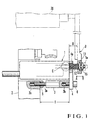
- Fig. 1 shows a moving amount detection apparatus for a plate cylinder in a printing press according to an embodiment of the present invention.
- a direct coupled type potentiometer 1 with a circular cylindrical detection body 1a which is linearly movable forward/backward is fixed to a holder 4 through a hexagonal adjuster bolt 3 in a bracket 2 fixed to a frame (not shown), such that a projection height T from the bracket 2 can be adjusted.
- the adjuster bolt 3 has a male screw portion 3a formed at its one end and a female screw portion 3b formed at its other end. With the male screw portion 3a of the adjuster bolt 3 threadably engaging with a threaded portion 2a of the bracket 2, when a nut 5 is fastened, the adjuster bolt 3 is fixed to the bracket 2 to be upright from it.
- the holder 4 to which the potentiometer 1 is fixed is fixed to the adjuster bolt 3 through a bolt 6 threadably engaging with the female screw portion 3b of the adjuster bolt 3.
- the holder 4 has a window 4a through which the detection member 1a passes.
- the press member 8 is fixed to the end shaft of a plate cylinder 20, serving as a movable body through a bracket or the like, to oppose the potentiometer 1.
- the press member 8 moves (is displaced) together with the plate cylinder 20 in the axial direction (direction of arrows A - B) of the plate cylinder 20.
- the press member 8 has a circular recess 8a in its surface opposing the potentiometer 1, and a through hole 8b, through which the detection body 1a of the potentiometer 1 is to movably extend, is formed in the bottom of the recess 8a.
- the description in Japanese Utility Model Laid-Open No. 64-42135 is incorporated in this specification.
- a snap ring 10 is axially mounted around the detection body 1a corresponding to the recess 8a and extending through the through hole 8b, and a washer 13 loosely fitted on the detection body 1a is interposed between the snap ring 10 and the bottom surface of the recess 8a.
- a pair of spring guides 9 and 11 are slidably supported on the detection body 1a, and a compression coil spring 12 is elastically mounted on the detection body 1a between the spring guides 9 and 11.
- the spring force of the compression coil spring 12 urges the spring guide 11 against the snap ring 10 so as to bias the detection body 1a in a direction to separate from the bracket 2.
- the detection body 1a of the potentiometer 1 is biased by the spring force of the compression coil spring 12 through the snap ring 10 in an extending direction (direction of arrow B), and is locked by the press member 8 through the washer 13.
- a snap ring 14 is axially mounted around the distal end of the detection body 1a projecting from the press member 8.
- a washer 15 is loosely fitted on the detection body 1a between the snap ring 14 and press member 8, and a clearance ⁇ is set between the washer 15 and press member 8.
- the clearance ⁇ prevents the press member 8 from being inclined. In other words, the backlash caused by inclination of the snap rings 10 and 14 is absorbed by the clearance ⁇ and does not adversely affect the press member 8.
- the detection body 1a is not inclined with respect to the axial direction. Hence, an excessive load can be prevented from acting on the detection body 1a to fracture it. Since the detection body 1a moves in the axial direction, it can move smoothly, and the accurate moving amount of the press member 8 can be detected.
- the press member 8 When a motor (not shown) is driven by a control unit (not shown) in order to perform register adjustment of the plate cylinder 20, the press member 8 also moves together with the plate cylinder 20 in the axial direction (direction of arrows A - B) of the press member 8.
- the press member 8 moves in a direction to move the detection body 1a backward, i.e., in the direction of an arrow A
- the detection body 1a moves in the direction of arrow A through the washer 13 and snap ring 10 against the spring force of the compression coil spring 12, and is retracted into the potentiometer 1.
- the driving operation of the motor is stopped, so the movement of the plate cylinder 20 is stopped and the movement of the press member 8 is also stopped.
- the detection body 1a When the press member 8 moves in the extending direction of the detection body 1a, i.e., in the direction of arrow B, the detection body 1a is extended by the spring force of the compression coil spring 12 to follow the press member 8. In other words, with the washer 13 being urged against the bottom surface of the recess 8a of the press member 8, the compression coil spring 12 biases the detection body 1a in the extending direction through the spring guide 11 and snap ring 10. Thus, the detection body 1a moves in the direction of arrow B together with the press member 8.
- the compression coil spring 12 is extended by its own spring force to urge the washer 13 against the bottom surface of the recess 8a of the press member 8 again through the spring guide 11 and snap ring 10.
- the washer 13 is restored to a normal state wherein it is urged by the compression coil spring 12 against the press member 8, and the washer 13 and press member 8 integrally move by a predetermined amount in the direction of arrow B.
- the detection body 1a When the detection body 1a is locked and the press member 8 has moved in the direction of arrow A, the detection body 1a is biased in the compression direction of the compression coil spring 12 through the washer 13 and snap ring 10, so the detection body 1a is unlocked in the same manner as that described above.
- the washer 13 is urged against the press member 8, in the same manner as in the state before the press member 8 starts moving, and the relative position relationship between the press member 8 and detection body 1a becomes identical to that obtained before the press member 8 starts moving.
- the moving amount of the press member 8 becomes equal to that of the detection body 1a, and the detection body 1a correctly detects the moving amount of the press member 8.
- the fastened nut 5 is loosened, and the fastened bolt 6 is loosened to separate the holder 4 from the adjuster bolt 3 to which it has been fixed. Subsequently, the adjuster bolt 3 is rotated clockwise/counterclockwise by a spanner or the like, thereby adjusting the projection height T of the adjuster bolt 3.
- the nut 5 is fastened to fix the adjuster bolt 3 to the bracket 2, and the bolt 6 is fastened to fix the holder 4 to the adjuster bolt 3.
- the detection body 1a can detect the moving amount of the press member 8 correctly and reliably.
- the potentiometer 1 is fixed to the bracket 2 as a stationary side, and the press member 8 is provided to the plate cylinder 20 side as the detection target side.
- the potentiometer 1 may be provided to the plate cylinder 20 side, and the press member 8 may be fixed to the bracket 2.
- the compression coil spring 12 urges one washer 13 against the press member 8 with its spring force, so the detection body 1a moves to follow the movement of the press member 8.
- no clearance ⁇ may be provided between the press member 8 and the other washer 15, but the press member 8 may be sandwiched by the two washers 13 and 15, and the press member 8 and detection body 1a may be directly connected to each other through the two washers 13 and 15. In this case, the compression coil spring 12 becomes unnecessary.
- the above embodiment exemplifies a case in the printing press wherein plate register adjustment of the plate cylinder 20 is controlled by the potentiometer 1.
- the present invention is not limited to this, but can also be applied to position detection apparatuses for various types of movable bodies that move linearly.
- the detection body As has been described above, according to the present invention, as the operational member moves, the detection body is also forced to move. Thus, the detection body is moved reliably. As a result, the reliability of the position detection precision for the movable body is improved. Since the distance between the detection means and operational member can be adjusted, detection can be performed correctly and reliably.
Landscapes
- Physics & Mathematics (AREA)
- General Physics & Mathematics (AREA)
- Engineering & Computer Science (AREA)
- Mechanical Engineering (AREA)
- Measurement Of Length, Angles, Or The Like Using Electric Or Magnetic Means (AREA)
Applications Claiming Priority (2)
| Application Number | Priority Date | Filing Date | Title |
|---|---|---|---|
| JP2000171921 | 2000-06-08 | ||
| JP2000171921 | 2000-06-08 |
Publications (1)
| Publication Number | Publication Date |
|---|---|
| EP1162065A1 true EP1162065A1 (fr) | 2001-12-12 |
Family
ID=18674408
Family Applications (1)
| Application Number | Title | Priority Date | Filing Date |
|---|---|---|---|
| EP01113902A Withdrawn EP1162065A1 (fr) | 2000-06-08 | 2001-06-07 | Dispositif pour détecter le déplacement d'un objet en mouvement |
Country Status (2)
| Country | Link |
|---|---|
| US (1) | US20010050698A1 (fr) |
| EP (1) | EP1162065A1 (fr) |
Citations (5)
| Publication number | Priority date | Publication date | Assignee | Title |
|---|---|---|---|---|
| DE1961229B1 (de) * | 1969-12-05 | 1971-04-08 | Sortimat Creuz & Co | Tastvorrichtung zum ermitteln mehrerer pruefmasse |
| JPS58150801A (ja) * | 1982-01-28 | 1983-09-07 | Tokico Ltd | 車高検出器 |
| EP0096563A2 (fr) * | 1982-06-04 | 1983-12-21 | Harris Graphics Corporation | Procédé et dispositif pour déterminer des positions dans une machine à imprimer des bandes |
| DE3405455C1 (de) * | 1984-02-16 | 1985-08-14 | M.A.N.- Roland Druckmaschinen AG, 6050 Offenbach | Umfangsregister-Einstellvorrichtung an Rotationsdruckmaschinen |
| DE19606849A1 (de) * | 1995-02-27 | 1996-08-29 | Mitsubishi Heavy Ind Ltd | Registereinstellvorrichtung für eine Druckmaschine |
-
2001
- 2001-06-07 EP EP01113902A patent/EP1162065A1/fr not_active Withdrawn
- 2001-06-07 US US09/878,072 patent/US20010050698A1/en not_active Abandoned
Patent Citations (5)
| Publication number | Priority date | Publication date | Assignee | Title |
|---|---|---|---|---|
| DE1961229B1 (de) * | 1969-12-05 | 1971-04-08 | Sortimat Creuz & Co | Tastvorrichtung zum ermitteln mehrerer pruefmasse |
| JPS58150801A (ja) * | 1982-01-28 | 1983-09-07 | Tokico Ltd | 車高検出器 |
| EP0096563A2 (fr) * | 1982-06-04 | 1983-12-21 | Harris Graphics Corporation | Procédé et dispositif pour déterminer des positions dans une machine à imprimer des bandes |
| DE3405455C1 (de) * | 1984-02-16 | 1985-08-14 | M.A.N.- Roland Druckmaschinen AG, 6050 Offenbach | Umfangsregister-Einstellvorrichtung an Rotationsdruckmaschinen |
| DE19606849A1 (de) * | 1995-02-27 | 1996-08-29 | Mitsubishi Heavy Ind Ltd | Registereinstellvorrichtung für eine Druckmaschine |
Non-Patent Citations (1)
| Title |
|---|
| PATENT ABSTRACTS OF JAPAN vol. 007, no. 270 (P - 240) 2 December 1983 (1983-12-02) * |
Also Published As
| Publication number | Publication date |
|---|---|
| US20010050698A1 (en) | 2001-12-13 |
Similar Documents
| Publication | Publication Date | Title |
|---|---|---|
| US7540571B2 (en) | Motor-driven disk brake system | |
| US6910694B2 (en) | Electrical tool with a quick-action clamping device | |
| JPH0317612B2 (fr) | ||
| JPH0722854B2 (ja) | ロボツト・グリツパをロボツト・アームに連結するための追従型機構 | |
| US7448249B2 (en) | Clutch actuation control system with adjustable position encoder assembly | |
| US4114747A (en) | Switching bearing assembly for a motor-driven spindle | |
| US20010050698A1 (en) | Moving amount detection apparatus for movable body | |
| JPS6436451A (en) | Remotely controllable adjusting means elastically changing registration rail | |
| US4429777A (en) | Automatic locking and adjustment assembly | |
| US5447083A (en) | Linear link selectively providing for lost motion | |
| US4976167A (en) | Tilt-telescope steering column | |
| US6009801A (en) | Method for safeguarding or protecting against penetration by foreign bodies into a roller nip | |
| JP2002062125A (ja) | 移動体の移動量検出装置 | |
| EP1312833A1 (fr) | Dispositif mobile a arbre de transmission | |
| EP1516726B1 (fr) | Dispositif de verrouillage d'un élément mobile | |
| JP2936979B2 (ja) | クラッチ調整装置及びクラッチの調整方法 | |
| JP3335614B2 (ja) | ガイド調整装置 | |
| JP3880686B2 (ja) | 転造盤のセンタ台装置 | |
| JPH08152Y2 (ja) | 産業用ロボットのフローティングユニット | |
| US5826510A (en) | Adjustment device for adjusting the height of gripper impact bars disposed diametrically opposite one another on sheet-guiding cylinder of a printing press | |
| JPH0222225Y2 (fr) | ||
| JP2002283148A (ja) | プロジェクションナットの供給装置 | |
| JP2596213Y2 (ja) | 研削砥石の芯出し調整機構 | |
| GB2071284A (en) | Hydraulic brake circuit | |
| US6253895B1 (en) | Adjustable bushing flange for clutch |
Legal Events
| Date | Code | Title | Description |
|---|---|---|---|
| PUAI | Public reference made under article 153(3) epc to a published international application that has entered the european phase |
Free format text: ORIGINAL CODE: 0009012 |
|
| AK | Designated contracting states |
Kind code of ref document: A1 Designated state(s): AT BE CH CY DE DK ES FI FR GB GR IE IT LI LU MC NL PT SE TR |
|
| AX | Request for extension of the european patent |
Free format text: AL;LT;LV;MK;RO;SI |
|
| AKX | Designation fees paid | ||
| REG | Reference to a national code |
Ref country code: DE Ref legal event code: 8566 |
|
| STAA | Information on the status of an ep patent application or granted ep patent |
Free format text: STATUS: THE APPLICATION IS DEEMED TO BE WITHDRAWN |
|
| 18D | Application deemed to be withdrawn |
Effective date: 20020613 |