EP1162428A2 - Verfahren und Vorrichtung zum Zünden eines Gefechtskopfes bei zielverfolgenden Lenkflugkörpern - Google Patents
Verfahren und Vorrichtung zum Zünden eines Gefechtskopfes bei zielverfolgenden Lenkflugkörpern Download PDFInfo
- Publication number
- EP1162428A2 EP1162428A2 EP01113715A EP01113715A EP1162428A2 EP 1162428 A2 EP1162428 A2 EP 1162428A2 EP 01113715 A EP01113715 A EP 01113715A EP 01113715 A EP01113715 A EP 01113715A EP 1162428 A2 EP1162428 A2 EP 1162428A2
- Authority
- EP
- European Patent Office
- Prior art keywords
- target
- hit
- ignition delay
- predicted
- guided missile
- Prior art date
- Legal status (The legal status is an assumption and is not a legal conclusion. Google has not performed a legal analysis and makes no representation as to the accuracy of the status listed.)
- Granted
Links
Images





Classifications
-
- F—MECHANICAL ENGINEERING; LIGHTING; HEATING; WEAPONS; BLASTING
- F42—AMMUNITION; BLASTING
- F42C—AMMUNITION FUZES; ARMING OR SAFETY MEANS THEREFOR
- F42C9/00—Time fuzes; Combined time and percussion or pressure-actuated fuzes; Fuzes for timed self-destruction of ammunition
- F42C9/14—Double fuzes; Multiple fuzes
- F42C9/148—Proximity fuzes in combination with other fuzes
-
- F—MECHANICAL ENGINEERING; LIGHTING; HEATING; WEAPONS; BLASTING
- F42—AMMUNITION; BLASTING
- F42C—AMMUNITION FUZES; ARMING OR SAFETY MEANS THEREFOR
- F42C13/00—Proximity fuzes; Fuzes for remote detonation
Definitions
- the invention relates to a method for igniting a warhead targeting guided missiles, one impact detonator and one Have proximity fuses for firing a warhead.
- the invention further relates to a device for igniting a warhead targeting guided missiles, one impact detonator and one Have proximity detonators for igniting a warhead, the Proximity detonator ignites the warhead with the ignition delay time.
- Guided missiles are guided to a target by a seeker head.
- a search head contains an image-resolution detector, usually one two-dimensional arrangement of detector elements.
- the resulting picture of a the visual field scene containing the target is switched to image processing means.
- Steering signals are obtained from the image processing, by means of which the Guided missile is guided to the target. If closer to the target delivers the seeker head takes a picture of the target, the bigger the farther the guided missile is approaches the goal.
- the guided missile contains a warhead, i.e. an explosive charge through which the target should be destroyed with the greatest possible certainty.
- the trajectory of the The guided missile can have some of the ideal trajectory due to various influences differ. This may be due to e.g. through the encounter geometry, for example through Maneuvers of the target, due to inaccuracies in the guidance of the guided missile or due to limitations in the maneuverability of the guided missile. In one In the event the guided missile will not hit the target at the optimal location.
- the Guided missiles can even reach the target at a greater or lesser distance fly by.
- the guided missile has an impact detonator. The Impact detonator ignites the warhead when the guided missile hits the Target hits.
- the guided missile also has a proximity fuse.
- the Proximity detonator responds when the guided missile reaches the target sufficiently far has approached. It ignites the warhead even when the missile is on it Target flies by. The ignition takes place with an ignition delay time after the response of the proximity fuse. This ignition delay time is chosen so that the ignition in Flyby occurs at a time when the detonating warhead and the splinters thrown away by this cause the greatest possible damage to the target to serve.
- the ignition delay time is usually a fixed, empirically found value.
- the invention is based on the object of a guided missile with impact and proximity detonators to cause the warhead to ignite so that the Damage to the target becomes as large as possible.
- Hit lists can be set according to size and direction. According to the basic idea According to the invention, this hit repository is now dependent on various predictable influencing factors predicted. Depending on this predicted The hit delay is then set to the ignition delay time.
- the dependency of the hit list on the influencing variables and on the remaining flight time of the Guided missile can be determined and saved by simulation.
- the influencing variables can include steering-specific variables such as the line of sight rotation rate, that result from the geometry of the target and guided missile.
- the influencing factors can also missile-specific sizes such as rudder deflection or Include lateral acceleration. These influencing factors are particularly important when the guided missile reaches the limits of its maneuverability.
- Influencing variables e.g. the line of sight rotation rate. Under These influencing factors are taken into account for a predetermined remaining flight time predicted hit lists determined. The hit lists determined in this way are replaced by the Determination of the underlying remaining flight time delayed provided at an exit. When the proximity detonator responds, predicted hit placements are available Available, which are based on the influencing factors, which before the given associated remaining flight times were measured and now relate to the time, to which the proximity sensor responds. Then there is no remaining flight time to be estimated, which is usually only possible with great inaccuracy.
- a hit repository obtained in this way on the basis of a single remaining flight time can to be adulterated by noise.
- Embodiments of the device are the subject of further claims.
- the guided missile contains an impact detonator, which if the Missile responsive to the target and the warhead, possibly with a very small one Ignition delay time, ignites inside the target.
- the guided missile continues to contain a proximity fuse.
- the proximity fuse responds when the guided missile has approached the target within a short distance.
- the proximity fuse fires even if the guided missile does not hit the target directly but in a short distance past the target.
- the ignition is usually carried out here an ignition delay time.
- a detonating warhead of a guided missile has two Effects, namely a pressure effect and a splinter effect. The pressure effect comes into play especially when the warhead is within the target or in detonated in the immediate vicinity of the target.
- Detonation outside the target can result in a Destruction or damage to the target is caused by the splinter effect. If the Guided missile scored a direct hit, i.e. hits the target directly, then is it is best if the warhead is fired by the impact detonator. During a flyby, the ignition is triggered by the proximity fuse with a such ignition delay time that there is a maximum splintering effect.
- the response point of the proximity fuse is often poorly defined. This Contact point can e.g. depend on the type of destination or the direction which of the guided missiles approaches the target. It can therefore happen that at early response of the proximity fuse and fixed ignition delay time the warhead is fired before the guided missile hits the target, too if the guided missile hits a direct hit without this premature ignition would. Then the effectiveness of the warhead would not be maximum and that Destroy probability reduced. In this case, the ignition delay would be longer of the proximity fuse is more favorable, since this makes the impact fuse effective would allow.
- the ignition delay time is made dependent on the predicted one Hit storage.
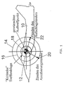
- the "hit repository" is explained with reference to FIG. 1.
- 10 is a target, here an enemy fighter aircraft, as it is from the image-resolving detector of the guided missile is seen. On this goal lies a “desired aimpoint". If the missile is directly on hitting this desired point of impact is a maximum effect of the warhead guaranteed. This desired point of impact is designated by 12 in FIG. The The actual point of impact now usually deviates from the desired one Impact point 12 by distance and direction. This is the "hit repository”.
- the Hit depots are in Fig.1 by circles 14, 16, 18 in the manner of a target indicated. Is the point of impact still within the inner circle 18, the one "Critical hit storage" determined, there is still a direct hit, i.e. the missile hits the target directly. The missile can be fired at larger hit areas fly past goal 10.
- the warhead is then ignited by the Proximity igniter, as shown in Fig. 1 by point 20. But it can also the amount after a larger number of hits is a direct hit, as shown in Fig.1 Point 22 is shown.
- the ignition takes place the warhead by the proximity fuse with an optimal ignition delay time, so that maximum splintering effect is achieved.
- the impact detonator should be effective within circle 18 or also in point 22 become.
- the point of impact is now based on observed influencing variables predicted. This is with reference to FIGS. 2 to 4 for the influencing variable "Line of sight rotation rate ⁇ ⁇ " explained for the flat case.
- R is the current distance from guided missile 24 and target 26
- V r is the relative speed between guided missile 24 and target 26
- t r is the remaining flight time. It is assumed that the missile and target continue to move unaccelerated during the short remaining flight time.
- ⁇ is the angle between the vectors of the Target distance and relative speed.
- the relative speed vector V r will always have a certain misalignment ⁇ with respect to the target 26.
- the line of sight rotation rate increases inversely proportional to the remaining distance
- increases at a given residual distance
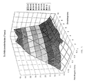
- FIG. 5 shows such a one obtained from a six-dimensional simulation Relationship between hit storage and line of sight rate as a function of Remaining flight time.
- the horizontal coordinates in Fig. 5 are the remaining flight time and hit list.
- the vertical coordinate is the mean line of sight rotation rate.
- Fig. 5 clearly the expected almost linear increase in line of sight rotation as a function of Hit storage.
- Figures 5 and 6 show steering-specific parameters that depend on the relative movement of Guided missile 24 and target 26 are determined as indicators of the size of the Hit storage.
- missile-specific parameters can also be indicators for the size of the hit repository.
- a not perfectly adjusted one Autopilot give rise to restless flight behavior of the guided missile, which in turn can lead to larger hit lists.
- Operation of the guided missile can also take place the limits of its aerodynamic or flight mechanical performance as Indicator for a larger number of hits tend to be used. Such a Operation can be due to high angles of attack, large rudder deflections or high Lateral accelerations must be marked. These influences are referred to below as Referred to as "stress factors".
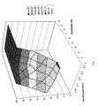
- Fig. 7 shows that also obtained by six-dimensional simulation Relationship between hit placement and rudder deflection as a function of Remaining flight time. Large rudder deflections usually occur in connection with large ones Angles of attack, large lateral accelerations or high rotation rates. Fig. 7 show that large rudder deflections, especially if they have the maximum rudder deflection reach, are associated with larger hit lists.
- Fig. 8 finally shows the relationship between obtained in a similar manner Hit placement and measured lateral acceleration as a function of the remaining flight time.
- the Horizontal coordinates in Fig. 8 are the remaining flight time and hit list.
- the vertical Coordinate is the measured mean lateral acceleration of the guided missile.
- a high lateral acceleration indicates that the encounter in the border area of the Performance of the guided missile takes place, e.g. near the inner Firing range limit.
- the high lateral acceleration can also be connected to a large angle of attack of the guided missile.
- lateral acceleration shows a clear connection with the Hit storage, which increases for high lateral accelerations, and with the remaining flight time.
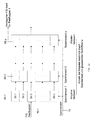
- the various influencing variables namely on the one hand the steering-specific parameters such as line-of-sight rotation rate ⁇ prepare and line-of-sight spin and on the other hand, the missile-specific parameters such as rudder deflection and lateral acceleration, as shown in FIG. 9, are switched to a hit deposit predictor 28.
- the remaining flight time (“time-to-go"), which is estimated by image processing of a viewfinder image of the seeker head of the guided missile, is also applied to the hit storage predictor. This is one way of considering the remaining flight time.
- the hit placement predictor 28 predicts either a direct hit with a signal at an output 30 or a near miss ("near miss") with a signal at an output 32.
- the signals at the outputs 30 and 32 are connected to an igniter section 34.
- Detonator section 34 includes a proximity detonator which responds when the missile approaches the target. This is indicated by an input 36 "target detection”.
- a first ignition delay time table 38 is assigned to the proximity fuse, which table delivers a relatively long first ignition delay time for the proximity fuse. This ignition delay time table 38 takes effect when the hit deposit predictor signals a direct hit at output 30.
- a second ignition delay time table 40 is also assigned to the proximity sensor, which table delivers a shorter, second ignition delay time for the proximity sensor.
- the first ignition delay time is chosen so long that the impact detonator of the guided missile can take effect before the warhead can be ignited via the proximity sensor. This ensures that the warhead cannot be fired prematurely via the proximity sensor before the missile strikes the target. This could happen if the proximity sensor responds very early and the ignition delay time is set relatively short.
- the second ignition delay time is shorter than the first ignition delay time. This second ignition delay time is selected so that when the guided missile flies past the target, maximum destruction is achieved at the target by splintering.
- an ignition pulse is generated at an output 42 generated, the ignition delay time the direct hit or the flyby in the above described meaning corresponds.
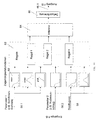
- Eig.10 is a block diagram and shows the formation of the "direct hits" - and "Flyby" signals at outputs 30 and 32.
- the Measurement or estimation of those needed to determine the hit location Difficulty remaining.
- this remaining flight time from the Estimate the image processing and apply it to the predictor 28 as a measured variable in the preferred embodiment of FIG. 10
- an estimate of the Hit storage made in parallel for different predetermined remaining flight times, whereby the current parameters are used as a basis.
- the so estimated Hit lists are given around the predefined basis used for the assessment Remaining flight time delayed.
- Estimates of the hit list are available, e.g.
- the influencing variables described with reference to FIGS. 5 to 8 or Parameters provide information on the expected number of hits.
- the hit tray leaves but can not be easily calculated from this according to a certain algorithm. For this reason, the hit list is estimated on the basis of the influencing variables and the assumed remaining flight time by "fuzzy inference systems". This is in Fig.11 shown.
- the influencing factors are based on membership functions in Linguistic variables such as "large”, “medium”, "small” implemented. Since the Membership functions usually overlap, a certain value can be a Influencing variable with certain percentages ("belonging factors") different be assigned to linguistic variables, ie approximately 75% "large” and 25% “medium” his.
- the linguistic quantities are shaped according to given inference rules "If ..., then ..” processed.
- the results of the inference are determined in accordance with the Affiliation factors linked.
- the "defuzzification” then results in one numerical output variable. This is a known technique.
- fuzzy inference systems 44.1, 44.2 ... 44.m are provided in FIG.
- Each of these fuzzy inference systems is constantly acted upon by the current influencing variables and requires an associated predetermined remaining flight time t r1 , t r2 ... t m .
- the fuzzy inference systems deliver numerical output variables in the form of predicted hit depots at outputs 46.1, 46.2 ... 46.m.
- the output variables are each delayed by the associated remaining flight time t r1 , t r2 ... t m by means of shift registers 48.1, 48.2, ... 48.m.
- wm are available that are comparable in terms of time to the remaining flight times. These predicted hit lists are weighted in a summing point 52. The weighted sum is applied to an evaluation circuit 54. The evaluation circuit 54 then delivers the signals "direct hit” or “flyby” at the outputs 30 and 32, as was explained with reference to FIG.
- FIG. 11 shows schematically one of the fuzzy inference systems shown in FIG.
- the fuzzy inference system e.g. 44.1, has inputs 56.1, 56.2 ... 56.n for the various steering-specific or missile-specific influencing variables or parameters. Furthermore, the fuzzy inference system contains an input 58 to which a predetermined remaining flight time t r1 ,... Assigned to the respective fuzzy inference system is applied. Each input is, as shown completely in FIG. 11 for input 56.1, connected in parallel to sorting elements 60, by means of which the input variable present, for example the line of sight rotation rate ⁇ ⁇ , with a membership factor of a linguisian variable determined by a membership function "small", "medium” or "large” is assigned. The linguistic variables thus obtained are connected to a rule bank 62.
- All of the rules mentioned ie all rules in which parameters appear as linguistic variables with a membership factor, provide linguistic variables with membership factors that result from the membership factors of the parameters that occur. This is represented by block 64 in FIG.
- the results of the various rules are summed up and again provide a numerical value. This is shown in FIG. 11 by a block 66 "defuzzification" with an output 46.1.
- FIG. 12 shows a shift register for delaying the predicted hit storage by one Remaining flight time, e.g. corresponds to the shift register 48.1 of Fig.10.
- the shift register 48.1 contains registers 68.1, 68.2 ... 68.p.
- register 68.1 with bits 1 to k is the fuzzy inference system 44.1 from the output 46.1 of the same read in the current value of the predicted hit list.
- the shift register 48.1 is, like the other shift registers, from a memory clock at a clock input 70 controlled.
- the current predicted hit storage from the fuzzy inference system 44.1 is read into register 68.1 as a memory word. Through a This memory word is clock pulse from register 68.1 to register 68.2 transfer.
- the memory word previously stored in register 68.2 becomes simultaneous transferred to the next register 68.3, etc., while in register 68.1 the new one current predicted hit list is read.
- After p clock pulses that the correspond to the specified remaining flight time, is that read into register 68.1 Memory word arrives in register 68p and is there for reading out as a delayed predicted hit list w1 (Fig. 10) is available.
Landscapes
- Engineering & Computer Science (AREA)
- General Engineering & Computer Science (AREA)
- Aiming, Guidance, Guns With A Light Source, Armor, Camouflage, And Targets (AREA)
- Radar Systems Or Details Thereof (AREA)
Abstract
Description

- Fig.1
- veranschaulicht die Definition der Trefferablage und der "Kritischen Trefferablage" bezogen auf ein vom Sucher des Lenkflugkörpers erfaßtes Ziel.
- Fig.2
- veranschaulicht die Relativgeometrie Lenkflugkörper-Ziel.
- Fig.3
- veranschaulicht die Relativgeschwindigkeit Lenkflugkörper
- Fig.4
- veranschaulicht die Annäherungsgeometrie.
- Fig.5
- ist ein durch Simulation gewonnenes Diagramm und zeigt den Zusammenhang zwischen Trefferablage und Sichtliniendrehrate als Funktion der Restflugzeit.
- Fig.6
- ist ein durch Simulation gewonnenes Diagramm und zeigt den Zusammenhang zwischen Trefferablage und Sichtliniendrehbeschleunigung als Funktion der Restflugzeit.
- Fig.7
- ist ein durch Simulation gewonnenes Diagramm und zeigt den Zusammenhang zwischen Trefferablage und maximalem Ruderauschlag als Funktion der Restflugzeit.
- Fig.8
- ist ein durch Simulation gewonnenes Diagramm und zeigt den Zusammenhang zwischen Trefferablage und gemessener Querbeschleunigung als Funktion der Restflugzeit.
- Fig.9
- ist ein Blockdiagramm und zeigt im Prinzip die Einbindung einer Direkttreffer-Prädiktion an der Schnittstelle zwischen Lenkeinheit und Zünder.
- Fig.10
- ist ein schematisches Blockdiagramm und veranschaulicht die Prädiktion der Trefferablage.
- Fig.11
- veranschaulicht ein zur Prädizierung der Trefferablage vorgesehenes "Fuzzy-Inferenz"-System.
- Fig.12
- veranschaulicht die Verzögerung der prädizierten Zielablage um die bei der Prädizierung vorausgesetzte Restflugzeit.


Claims (20)
- Verfahren zum Zünden eines Gefechtskopfes bei zielverfolgenden Lenkflugkörpern, die einen Aufschlagzünder und einen Annäherungszünder aufweisen, der bei Annäherung des Flugkörpers an ein Ziel anspricht, wobei eine Detonation des Gefechtskopfes durch den Aufschlagzünder beim Auftreffen des Flugkörpers auf das Ziel und durch den Annäherungszünder mit einer Zündverzugszeit gegenüber dem Ansprechen des Annäherungszünders ausgelöst wird, gekennzeichnet durch die Verfahrensschritte:Erfassen von Einflußgrößen, welche die Art der Begegnung des Lenkflugkörpers mit dem Ziel beeinflussen, undEinstellen der Zündverzugszeit in Abhängigkeit von solchen Einflußgrößen.
- Verfahren nach Anspruch 1, dadurch gekennzeichnet, daßaus den erfaßten Einflußgrößen eine prädizierte Trefferablage bestimmt wird unddie Zündverzugszeit nach Maßgabe der so prädizierten Trefferablage eingestellt wird.
- Verfahren nach Anspruch 2, dadurch gekennzeichnet, daß dann, wenn die prädizierte Trefferablage einen Direkttreffer erwarten läßt, eine so lange Zündverzugszeit eingestellt wird, daß die Zündung des Gefechtskopfes bei Auftreffen des Lenkflugkörpers auf das Ziel durch den Aufschlagzünder erfolgen kann.
- Verfahren nach Anspruch 2 oder 3, dadurch gekennzeichnet, daß dann, wenn die prädizierte Trefferablage einen Vorbeiflug des Lenkflugkörpers an dem Ziel erwarten läßt, eine Zündverzugszeit eingestellt wird, die im Hinblick auf die Wirksamkeit des seitlich vom Ziel detonierenden Gefechtskopfes optimiert ist.
- Verfahren nach einem der Ansprüche 2 bis 4, dadurch gekennzeichnet, daß die Abhängigkeit der Trefferablage von den Einflußgrößen und von der Restflugzeit des Lenkflugkörpers durch Simulation ermittelt und gespeichert wird.
- Verfahren nach einem der Ansprüche 1 bis 5, dadurch gekennzeichnet, daß die Einflußgrößen solche Größen wie die Sichtliniendrehrate umfassen, die sich aus der Geometrie von Ziel und Lenkflugkörper ergeben.
- Verfahren nach einem der Ansprüche 1 bis 6, dadurch gekennzeichnet, daß die Einflußgrößen flugkörperspezifische Größen wie Ruderausschlag oder Querbeschleunigung umfassen.
- Verfahren nach einem der Ansprüche 4 bis 6, dadurch gekennzeichnet, daß die Restflugzeit aus einer Bildverarbeitung eines von einem bildauflösenden Suchkopf des Lenkflugkörpers gelieferten Zielbildes gewonnen wird.
- Verfahren nach Anspruch 2, dadurch gekennzeichnet, daß(a) aus den Einflußgrößen für eine vorgegebene Restflugzeit laufend eine prädizierte Trefferablage bestimmt wird, und(b) die so für eine bestimmte Restflugzeit prädizierte Trefferablage um diese Restflugzeit verzögert für die Bestimmung der Zündverzugszeit beim Ansprechen des Annäherungszünders bereitgestellt wird.
- Verfahren nach Anspruch 9, dadurch gekennzeichnet, daß(a) aus den Einflußgrößen parallel für verschiedene Restflugzeiten zugehörige prädizierte Trefferablagen bestimmt werden,(b) jede der für eine Restflugzeit bestimmte prädizierte Trefferablage um diese zugehörige Restflugzeit verzögert für die Bestimmung der Zündverzugszeit beim Ansprechen des Annäherungszünders bereitgestellt wird und(c) für die Bestimmung der Zündverzugszeit ein Mittel oder gewichtetes Mittel der zeitverzögert bereitgestellten prädizierten Trefferablagen gebildet wird.
- Vorrichtung zum Zünden eines Gefechtskopfes bei zielverfolgenden Lenkflugkörpern, die einen Aufschlagzünder und einen Annäherungszünder zum Zünden des Gefechtskopfes aufweisen, wobei der Annäherungszünder bei Annäherung an das Ziel anspricht und die Detonation des Gefechtskopfes mit einer Zündverzögerung gegenüber dem Ansprechen des Annäherungszünders auslöst,
gekennzeichnet durch(a) Mittel zum Erfassen von Einflußgrößen (σ ˙,...), welche die Art der Begegnung des Lenkflugkörpers (24) und des Ziels beeinflussen während des Fluges des Lenkflugkörpers (24), und (b) Einstellmittel (38,40) zum Einstellen der Zündverzugszeit des Annäherungszünders in Abhängigkeit von solchen Einflußgrößen.
 - Vorrichtung nach Anspruch 11, gekennzeichnet durch Mittel zum Bestimmen einer prädizierten Trefferablage aus den so bestimmten Einflußgrößen, wobei die Einstellgrößen nach Maßgabe der so bestimmten prädizierten Trefferablage einstellbar sind.
- Vorrichtung nach Anspruch 12, dadurch gekennzeichnet, daß(a) durch die Einstellmittel (38,40) dann, wenn die prädizierte Trefferablage einen Direkttreffer erwarten läßt, eine so lange Zündverzugszeit einstellbar ist, daß die Zündung des Gefechtskopfes bei Auftreffen des Lenkflugkörpers (24) auf das Ziel (26) durch den Aufschlagzünder erfolgen kann, und(b) durch die Einstellmittel dann, wenn die prädizierte Trefferablage einen Vorbeiflug des Lenkflugkörpers (24) an dem Ziel (26) erwarten läßt, eine Zündverzugszeit einstellbar ist, die im Hinblick auf die Wirksamkeit des seitlich vom Ziel detonierenden Gefechtskopfes optimiert ist.
- Vorrichtung nach Anspruch 13, gekennzeichnet durch Speichermittel, mittels derer die durch Simulation ermittelte Abhängigkeit der Trefferablage von den Einflußgrößen und von der Restflugzeit des Lenkflugkörpers (24) gespeichert ist.
- Vorrichtung nach einem der Ansprüche 12 bis 14, dadurch gekennzeichnet, daß die Mittel zum Erfassen der Einflußgrößen(a) Mittel zum Erfassen lenkspezifische Größen wie die Sichtliniendrehrate umfassen, die sich aus der Geometrie von Ziel und Lenkflugkörper ergeben, und(b) Mittel zum Erfassen lenkflugkörperspezifischer Größen wie Ruderausschlag oder Querbeschleunigung.
- Vorrichtung nach Anspruch 13, gekennzeichnet durch(a) einem bildauflösenden Suchkopf des Lenkflugkörpers, der ein Zielbild liefert, und(b) bildverarbeitende Mittel zur Abschätzung der Restflugzeit aus der Größenänderung des Zielbildes.
- Vorrichtung nach einem der Ansprüche 12 bis 14, gekennzeichnet durch(a) Mittel (44.1) zur Bestimmung der Trefferablage aus den Einflußgrößen für eine vorgegebene Restflugzeit und(b) Verzögerungsmittel (48.1), durch welche die für die vorgegebene Restflugzeit prädizierte Trefferablage um diese Restflugzeit verzögert für die Bestimmung der Zündverzugszeit beim Ansprechen des Annäherungszünders bereitstellbar ist.
- Vorrichtung nach Anspruch 17, dadurch gekennzeichnet, daß(a) die Mittel (44.1,44.2 ...) zur Bestimmung der Trefferablage aus den Einflußgrößen vermehrfacht in parallelen Kanälen vorgesehen sind, wobei jeder Kanal von den Einflußgrößen beaufschlagt ist und in den Kanälen prädizierte Trefferablagen für verschiedene Restflugzeiten bestimmt werden,(b) Verzögerungsmittel (48.1,48.2 ...) vorgesehen sind, durch welche jede der so für eine bestimmte Restflugzeit prädizierte Trefferablage um diese Restflugzeit verzögert für die Bestimmung der Zündverzugszeit beim Ansprechen des Annäherungszünders bereitstellbar ist.
- Vorrichtung nach Anspruch 18, dadurch gekennzeichnet, daß die zeitverzögert bereitgestellten prädizierten Trefferablagen für die Bestimmung der Zündverzugszeit auf Mittel (52) zur Bildung eines gewichteten Mittels der zeitverzögert bereitgestellten prädizierten Trefferablagen aufgeschaltet sind.
- Vorrichtung nach einem der Ansprüche 11 bis 19, dadurch gekennzeichnet, daß die die Mittel zur Bestimmung der Trefferablage aus den Einflußgrößen von einem Fuzzy-Inferenz-System gebildet sind.
Applications Claiming Priority (2)
| Application Number | Priority Date | Filing Date | Title |
|---|---|---|---|
| DE10028746 | 2000-06-10 | ||
| DE10028746A DE10028746A1 (de) | 2000-06-10 | 2000-06-10 | Verfahren und Vorrichtung zur Bestimmung der Zündverzugszeit bei zielverfolgenden Lenkflugkörpern |
Publications (3)
| Publication Number | Publication Date |
|---|---|
| EP1162428A2 true EP1162428A2 (de) | 2001-12-12 |
| EP1162428A3 EP1162428A3 (de) | 2004-02-25 |
| EP1162428B1 EP1162428B1 (de) | 2007-08-22 |
Family
ID=7645338
Family Applications (1)
| Application Number | Title | Priority Date | Filing Date |
|---|---|---|---|
| EP01113715A Expired - Lifetime EP1162428B1 (de) | 2000-06-10 | 2001-06-05 | Verfahren und Vorrichtung zum Zünden eines Gefechtskopfes bei zielverfolgenden Lenkflugkörpern |
Country Status (3)
| Country | Link |
|---|---|
| US (1) | US6584906B2 (de) |
| EP (1) | EP1162428B1 (de) |
| DE (2) | DE10028746A1 (de) |
Cited By (3)
| Publication number | Priority date | Publication date | Assignee | Title |
|---|---|---|---|---|
| EP2245420A4 (de) * | 2008-02-21 | 2012-09-19 | Rafael Advanced Defense Sys | Geführte waffe mit mehreren während des flugs umschaltbaren zündmodi |
| CN112035780A (zh) * | 2020-09-04 | 2020-12-04 | 清华大学 | 一种导弹末制导阶段杀伤效果计算方法 |
| CN114091226A (zh) * | 2021-09-26 | 2022-02-25 | 中国人民解放军63921部队 | 基于毁伤建筑物靶标侵彻计层飞行试验的再用评定方法 |
Families Citing this family (3)
| Publication number | Priority date | Publication date | Assignee | Title |
|---|---|---|---|---|
| US7261035B1 (en) * | 2005-01-31 | 2007-08-28 | United States Of America As Represented By The Secretary Of The Navy | Method and system for operation of a safe and arm device |
| US8834163B2 (en) * | 2011-11-29 | 2014-09-16 | L-3 Communications Corporation | Physics-based simulation of warhead and directed energy weapons |
| CN116679743B (zh) * | 2023-04-24 | 2026-03-20 | 中国人民解放军国防科技大学 | 拦截机动目标的非线性最优飞行时间控制制导方法 |
Family Cites Families (9)
| Publication number | Priority date | Publication date | Assignee | Title |
|---|---|---|---|---|
| US4168663A (en) * | 1954-12-01 | 1979-09-25 | The United States Of America As Represented By The Secretary Of The Army | Computer fuzes |
| US3877377A (en) * | 1955-01-17 | 1975-04-15 | Us Army | Proximity Fuze |
| US3613590A (en) * | 1956-02-15 | 1971-10-19 | Us Navy | Vt fuse with inherent capacity for pd action when on a normal approach collision course |
| US3850103A (en) * | 1973-12-04 | 1974-11-26 | Us Army | Computer interceptor proximity fuze |
| DE2514136C1 (de) * | 1975-03-29 | 1985-10-31 | Messerschmitt-Bölkow-Blohm GmbH, 8000 München | Zuendvorrichtung,bestehend aus einem Aufschlag- und einem UEberflugzuender |
| DE3011231A1 (de) * | 1980-03-22 | 1981-10-01 | Licentia Patent-Verwaltungs-Gmbh, 6000 Frankfurt | Schaltungsanordnung eines kombinierten annaeherungs- und aufschlagzuenders |
| JPH0718676B2 (ja) * | 1989-08-29 | 1995-03-06 | 三菱プレシジョン株式会社 | 近接信管装置 |
| JPH0718677B2 (ja) * | 1989-08-30 | 1995-03-06 | 三菱プレシジョン株式会社 | 近接信管装置 |
| US5696347A (en) * | 1995-07-06 | 1997-12-09 | Raytheon Company | Missile fuzing system |
-
2000
- 2000-06-10 DE DE10028746A patent/DE10028746A1/de not_active Withdrawn
-
2001
- 2001-06-05 EP EP01113715A patent/EP1162428B1/de not_active Expired - Lifetime
- 2001-06-05 DE DE50112899T patent/DE50112899D1/de not_active Expired - Lifetime
- 2001-06-08 US US09/877,346 patent/US6584906B2/en not_active Expired - Lifetime
Cited By (5)
| Publication number | Priority date | Publication date | Assignee | Title |
|---|---|---|---|---|
| EP2245420A4 (de) * | 2008-02-21 | 2012-09-19 | Rafael Advanced Defense Sys | Geführte waffe mit mehreren während des flugs umschaltbaren zündmodi |
| US8689692B2 (en) | 2008-02-21 | 2014-04-08 | Rafael Advanced Defense Systems Ltd. | Guided weapon with in-flight-switchable multiple fuze modes |
| CN112035780A (zh) * | 2020-09-04 | 2020-12-04 | 清华大学 | 一种导弹末制导阶段杀伤效果计算方法 |
| CN112035780B (zh) * | 2020-09-04 | 2022-05-31 | 清华大学 | 一种导弹末制导阶段杀伤效果计算方法 |
| CN114091226A (zh) * | 2021-09-26 | 2022-02-25 | 中国人民解放军63921部队 | 基于毁伤建筑物靶标侵彻计层飞行试验的再用评定方法 |
Also Published As
| Publication number | Publication date |
|---|---|
| EP1162428B1 (de) | 2007-08-22 |
| US20030047102A1 (en) | 2003-03-13 |
| EP1162428A3 (de) | 2004-02-25 |
| DE50112899D1 (de) | 2007-10-04 |
| DE10028746A1 (de) | 2001-12-13 |
| US6584906B2 (en) | 2003-07-01 |
Similar Documents
| Publication | Publication Date | Title |
|---|---|---|
| DE2833079C1 (de) | Lenkgeschoss | |
| EP1079198B1 (de) | Verfahren zur Bestimmung der Relativbewegung zwischen Flugkörper und Ziel | |
| DE2714688A1 (de) | Vorrichtung zur korrektur der flugbahn eines projektils | |
| DE3011231C2 (de) | ||
| EP0547391A1 (de) | Verfahren zur Erhöhung der Erfolgswahrscheinlichkeit bei der Flugkörperabwehr mittels eines fernzerlegbaren Geschosses | |
| DE69625927T2 (de) | Vorrichtung zur bekämpfung von luftzielen | |
| DE3303763C2 (de) | ||
| DE2830502A1 (de) | Steuervorrichtung fuer flugkoerper | |
| DE2452586C3 (de) | Verfahren und Vorrichtung zur Festlegung der Dauer des Flugweges eines Geschosses | |
| CH669659A5 (de) | ||
| DE2922583A1 (de) | Annaeherungszuender fuer panzerbekaempfungsflugkoerper | |
| EP1162428A2 (de) | Verfahren und Vorrichtung zum Zünden eines Gefechtskopfes bei zielverfolgenden Lenkflugkörpern | |
| DE3733962A1 (de) | Verfahren zur automatischen zielklassifizierung durch land- und wasserkampffahrzeuge sowie einrichtung zur durchfuehrung des verfahrens | |
| DE2325355B2 (de) | Verfahren zur Zielsteuerung eines Flugkörpers | |
| DE2650804C1 (de) | Einrichtung an tieffliegenden Waffentraegern zur Bekaempfung von Bodenzielen | |
| DE3906372C2 (de) | ||
| DE2922592C2 (de) | Verfahren zur Abwehr von Flugkörpern | |
| DE3013405A1 (de) | Verfahren zum vermeiden des nachrichtens von abschussgeraeten fuer ballistische flugkoerper | |
| DE2522927C2 (de) | System zur taeuschung, ablenkung und vernichtung von lenkwaffen | |
| DE4133405C2 (de) | Submunition für Tiefflugeinsatz | |
| DE3821309C2 (de) | ||
| DE3410942C1 (de) | Infrarot-Detektor | |
| EP2226607B1 (de) | Verfahren zum Zünden eines Gefechtskopfs einer Granate und Fahrzeug | |
| DE19540252C2 (de) | Verfahren zum Führen von Submunition in ein Ziel und Träger hierfür | |
| DE69719852T2 (de) | Vorrichtung zur Rollwinkelbestimmung eines Flugkörpers, insbesondere einer Munition |
Legal Events
| Date | Code | Title | Description |
|---|---|---|---|
| PUAI | Public reference made under article 153(3) epc to a published international application that has entered the european phase |
Free format text: ORIGINAL CODE: 0009012 |
|
| AK | Designated contracting states |
Kind code of ref document: A2 Designated state(s): AT BE CH CY DE DK ES FI FR GB GR IE IT LI LU MC NL PT SE TR |
|
| AX | Request for extension of the european patent |
Free format text: AL;LT;LV;MK;RO;SI |
|
| PUAL | Search report despatched |
Free format text: ORIGINAL CODE: 0009013 |
|
| AK | Designated contracting states |
Kind code of ref document: A3 Designated state(s): AT BE CH CY DE DK ES FI FR GB GR IE IT LI LU MC NL PT SE TR |
|
| AX | Request for extension of the european patent |
Extension state: AL LT LV MK RO SI |
|
| 17P | Request for examination filed |
Effective date: 20040821 |
|
| AKX | Designation fees paid |
Designated state(s): DE FR GB IT SE |
|
| 17Q | First examination report despatched |
Effective date: 20041126 |
|
| RAP1 | Party data changed (applicant data changed or rights of an application transferred) |
Owner name: DIEHL BGT DEFENCE GMBH & CO.KG |
|
| GRAP | Despatch of communication of intention to grant a patent |
Free format text: ORIGINAL CODE: EPIDOSNIGR1 |
|
| GRAS | Grant fee paid |
Free format text: ORIGINAL CODE: EPIDOSNIGR3 |
|
| GRAA | (expected) grant |
Free format text: ORIGINAL CODE: 0009210 |
|
| AK | Designated contracting states |
Kind code of ref document: B1 Designated state(s): DE FR GB IT SE |
|
| REG | Reference to a national code |
Ref country code: GB Ref legal event code: FG4D Free format text: NOT ENGLISH |
|
| REF | Corresponds to: |
Ref document number: 50112899 Country of ref document: DE Date of ref document: 20071004 Kind code of ref document: P |
|
| GBT | Gb: translation of ep patent filed (gb section 77(6)(a)/1977) |
Effective date: 20071001 |
|
| REG | Reference to a national code |
Ref country code: SE Ref legal event code: TRGR |
|
| ET | Fr: translation filed | ||
| PLBE | No opposition filed within time limit |
Free format text: ORIGINAL CODE: 0009261 |
|
| STAA | Information on the status of an ep patent application or granted ep patent |
Free format text: STATUS: NO OPPOSITION FILED WITHIN TIME LIMIT |
|
| 26N | No opposition filed |
Effective date: 20080526 |
|
| REG | Reference to a national code |
Ref country code: FR Ref legal event code: PLFP Year of fee payment: 15 |
|
| REG | Reference to a national code |
Ref country code: FR Ref legal event code: PLFP Year of fee payment: 16 |
|
| REG | Reference to a national code |
Ref country code: DE Ref legal event code: R081 Ref document number: 50112899 Country of ref document: DE Owner name: DIEHL DEFENCE GMBH & CO. KG, DE Free format text: FORMER OWNER: DIEHL BGT DEFENCE GMBH & CO. KG, 88662 UEBERLINGEN, DE |
|
| REG | Reference to a national code |
Ref country code: FR Ref legal event code: PLFP Year of fee payment: 17 |
|
| REG | Reference to a national code |
Ref country code: FR Ref legal event code: PLFP Year of fee payment: 18 |
|
| PGFP | Annual fee paid to national office [announced via postgrant information from national office to epo] |
Ref country code: FR Payment date: 20200619 Year of fee payment: 20 |
|
| PGFP | Annual fee paid to national office [announced via postgrant information from national office to epo] |
Ref country code: GB Payment date: 20200625 Year of fee payment: 20 Ref country code: SE Payment date: 20200625 Year of fee payment: 20 |
|
| PGFP | Annual fee paid to national office [announced via postgrant information from national office to epo] |
Ref country code: DE Payment date: 20200819 Year of fee payment: 20 |
|
| PGFP | Annual fee paid to national office [announced via postgrant information from national office to epo] |
Ref country code: IT Payment date: 20200625 Year of fee payment: 20 |
|
| REG | Reference to a national code |
Ref country code: DE Ref legal event code: R071 Ref document number: 50112899 Country of ref document: DE |
|
| REG | Reference to a national code |
Ref country code: GB Ref legal event code: PE20 Expiry date: 20210604 |
|
| REG | Reference to a national code |
Ref country code: SE Ref legal event code: EUG |
|
| PG25 | Lapsed in a contracting state [announced via postgrant information from national office to epo] |
Ref country code: GB Free format text: LAPSE BECAUSE OF EXPIRATION OF PROTECTION Effective date: 20210604 |