EP1162767A2 - Kommunikationssystem und Verfahren mit ultra breite Bande - Google Patents
Kommunikationssystem und Verfahren mit ultra breite Bande Download PDFInfo
- Publication number
- EP1162767A2 EP1162767A2 EP01202151A EP01202151A EP1162767A2 EP 1162767 A2 EP1162767 A2 EP 1162767A2 EP 01202151 A EP01202151 A EP 01202151A EP 01202151 A EP01202151 A EP 01202151A EP 1162767 A2 EP1162767 A2 EP 1162767A2
- Authority
- EP
- European Patent Office
- Prior art keywords
- data
- signal
- ultra
- stream
- notching
- Prior art date
- Legal status (The legal status is an assumption and is not a legal conclusion. Google has not performed a legal analysis and makes no representation as to the accuracy of the status listed.)
- Granted
Links
- 238000000034 method Methods 0.000 title claims abstract description 54
- 238000004891 communication Methods 0.000 title claims abstract description 53
- 230000001360 synchronised effect Effects 0.000 claims description 10
- 230000008569 process Effects 0.000 claims description 5
- 230000007480 spreading Effects 0.000 claims description 3
- 230000006870 function Effects 0.000 description 41
- 238000010586 diagram Methods 0.000 description 16
- 230000005540 biological transmission Effects 0.000 description 9
- 230000008901 benefit Effects 0.000 description 5
- 238000012886 linear function Methods 0.000 description 4
- 230000005855 radiation Effects 0.000 description 4
- 238000004590 computer program Methods 0.000 description 2
- 238000013500 data storage Methods 0.000 description 2
- 230000004048 modification Effects 0.000 description 2
- 238000012986 modification Methods 0.000 description 2
- 238000001228 spectrum Methods 0.000 description 2
- 230000009466 transformation Effects 0.000 description 2
- 230000004075 alteration Effects 0.000 description 1
- 239000011449 brick Substances 0.000 description 1
- 230000001413 cellular effect Effects 0.000 description 1
- 235000009508 confectionery Nutrition 0.000 description 1
- 238000010276 construction Methods 0.000 description 1
- 230000001419 dependent effect Effects 0.000 description 1
- 230000000694 effects Effects 0.000 description 1
- 238000005516 engineering process Methods 0.000 description 1
- 230000007246 mechanism Effects 0.000 description 1
- 230000000737 periodic effect Effects 0.000 description 1
- 230000008054 signal transmission Effects 0.000 description 1
- 238000006467 substitution reaction Methods 0.000 description 1
- 230000007704 transition Effects 0.000 description 1
Images


Classifications
-
- H—ELECTRICITY
- H04—ELECTRIC COMMUNICATION TECHNIQUE
- H04B—TRANSMISSION
- H04B7/00—Radio transmission systems, i.e. using radiation field
- H04B7/24—Radio transmission systems, i.e. using radiation field for communication between two or more posts
- H04B7/26—Radio transmission systems, i.e. using radiation field for communication between two or more posts at least one of which is mobile
- H04B7/2603—Arrangements for wireless physical layer control
Definitions
- This invention relates generally to wireless communications, and more particularly to ultra-wide band communication methods and systems.
- Ultra Wide Band (UWB) communication systems promise the maximum data rate for dc power expended. These systems are characterized by microwatts of transmitted power, bandwidths of ten times the data rate, digital coding for processing gains of 100 and center frequencies nearly the same as the bandwidth.
- Known UWB communication systems generally utilize wavelet waveforms having a bandwidth of several GHz.
- Present low-power (FCC Part 15, ISM bands) unlicensed, undefined modulation systems can transmit at RF power levels up to 0.7 mw, equivalent to 50 mv/m at a distance of 3 meters. This implies, for example, a transmit power level of -1.25 dBm for a dipole antenna (isotropic).
- intentional radiation RF power levels outside of the ISM bands is limited above 960 MHz to 500 uv/m (-21.25 dBm).
- UWB systems utilize the VHF and UHF bands for optimal in-building communication.
- VHF and UHF bands are two bands which are extremely sensitive to interference. These are the 1220 MHz and 1575 MHz global positioning system (GP) satellite link communication frequencies.
- GPS global positioning system
- Such a communication system would be very advantageous since it would be capable of short range, indoor communication without concern for signal losses associated with objects, e.g. walls, doors, windows, appliances, or other structures, due to reflections and the like, when operating within or near the broadcast frequency band (i.e., about 100-200 MHz).
- Such a communication system would thus be able to take advantage of the "sweet spot" range of frequencies (about 100-200 MHz) normally associated with indoor, battery operated devices.
- the present invention is directed to a low-cost, low-power, highly efficient ultra-wide band (UWB) communication system capable of selectively removing transmissions, without use of frequency notch filters or frequency shifting techniques, in designated bands that are narrow relative to the full bandwidth being utilized by the UWB communication system.
- UWB ultra-wide band
- One preferred embodiment of the present invention comprises an expander or spreader to process an incoming stream of data in the frequency domain into a waveform that is a function of time.
- One embodiment implements this expansion process by multiplying, via a mixer, the incoming stream of data with a chirp waveform from a chirp generator, thereby creating an output waveform in which each frequency is associated with a specific unit of time. Most preferably, each frequency will be associated with no more than a single unit of time.
- the processed waveform that is a function of time is then passed through a time notching process (as contrasted with known frequency notching techniques discussed above) in the time domain by synchronizing the processed waveform with a series of notches implemented in the time domain.
- a time notching process as contrasted with known frequency notching techniques discussed above
- a technique provides for a maximum limit on peak transmitter power such that a 100x factor in range may be attained in a quiet (i.e. home) environment, thereby enabling a transmitter to back-off to the minimum RF power for a given bit error rate.
- a technique provides an advantage when used in the same environment as unlicensed direct sequence (DS) radios.
- Present ISM band unlicensed DS radios are limited to 8 dBm with +10 dB gain, effectively providing 18 dBm transmitted power.
- the present invention therefore has a 1.75 dB advantage over unlicensed DS radios in the ISM bands.
- a technique enables several users to operate in the same frequency range without frequency channelization using several expensive IF filters, e.g. placing resonators at respective shunt elements in a lattice structure in an attempt to create a narrow-band notch.
- a technique enables precise ("brick wall”) notching of many forbidden frequency bands.
- a technique provides precise notching in association with signal processing (DSP) at baseband.
- DSP signal processing
- a technique enables near perfect (steep, minimal transition) excision of selected transmission frequencies.
- a technique enables implementation of a low-cost, low-power UWB communication system using known building blocks, e.g. reasonably good RF transceiver that does not require a high performance local oscillator (phase noise relaxation); chirp modulation; and demodulation circuits to implement spread-spectrum, such as an oversampled digital correlator, or SAW correlator, that does not require synchronization.
- known building blocks e.g. reasonably good RF transceiver that does not require a high performance local oscillator (phase noise relaxation); chirp modulation; and demodulation circuits to implement spread-spectrum, such as an oversampled digital correlator, or SAW correlator, that does not require synchronization.
- FIG. 1 is a diagram illustrating the frequency characteristics of a common RF notch filter 100 known in the art.
- a communication signal waveform 102 covers a wide range of frequencies in which it is desired to eliminate signal transmissions in a particular frequency band 104.
- Present frequency notch filters are generally costly to implement and are also lossy in the pass band frequencies due to limitations regarding known methods of physically implementing frequency notch filters.
- Figure 2 is a diagram illustrating a frequency shifting technique for excising a band of frequencies 200.
- This technique is useful where it is understood and accepted that many frequencies lying outside specific narrow frequency bands, e.g. 202, 204, are excised, even though only specific narrow frequency bands necessarily are required to be excised. Importantly, this technique may not be useful where the resulting operating range of frequencies will fall too high in the frequency spectrum, due to additional propagation loss which is proportional to f 2 .
- FIG 3 is a diagram illustrating a transform function 300 in which frequency is a linear function of time, f(t).
- Figure 4 is a diagram illustrating a transform function 400 in which frequency is a non-linear function of time, f(t).
- Figure 5 is a diagram illustrating a transform function 500 in which frequency is a discrete function of time, f(t). Any of the transform functions 300, 400, 500 can be implemented in association with a requisite expander or spreader to generate a communication signal in which a frequency waveform is a function of time. As described above, precise excision of particular frequencies or frequency bands is not practical or even feasible at baseband due to physical limitations associated with known frequency notching techniques and filters.
- Waveform 600 is a narrow band signal comprising pulses transmitted at 30 MHz. Each data pulse therefore is transmitted in a time interval of 0.033 usec (1/30MHz).
- the waveform 600 is one input to a mixer 602.
- a transform generator 604 such as a chirp generator generates a signal that is another input to the mixer 602.
- any transform function can be used so long as the expander generates a waveform that is a function of time. This function need not be monotonic, linear, or continuous.
- the present invention is not so limited however, and it shall be understood that a spreader can also be used to generate a waveform that is a function of time under appropriate circumstances well known to those skilled in the art.
- a chirp generator is thus exemplified herein only for purposes of explanation of the principles of the present invention.
- the chirp generator then generates a signal such as depicted in Figure 3 in which frequency is a function of time synchronized to the input data rate and that is repeated every 0.033 usec.
- the waveform 600 is transformed into a data stream 606 in which the transmitted data is represented as a function of time.
- Figure 7 is a diagram illustrating operation of a compressor.
- a compressor operates to recover the original transmission waveform that was transformed by the expander or spreader as described above.
- the transformed waveform (data stream 606) is received via a receiver antenna 700, sent through a buffer amplifier 702 and then to a mixer 704 where the data stream 606 is mixed with a signal generated by an inverse transform generator 706 such as an inverse chirp generator.
- the expander for example, comprises a function of frequency H ( f ) whose magnitude is unitary over the frequency range of interest.
- the expander also comprises a quadratic phase function ⁇ ( f )in which slope varies as a function of frequency.
- the compressor also has an
- the compressor has a quadratic phase function ⁇ ( f ) in which slope varies inversely as a function of frequency.
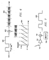
- FIG 8 is a diagram illustrating a system and method 800 of implementing a low-cost, low-power ultra-wide band (UWB) communication system according to one embodiment of the present invention.
- a data signal 802 is first seen generated over a 30-MHz frequency band. This data signal 802 is passed through an expander 804 as described herein above. Although described in association with an expander 804, those skilled in the art will readily appreciate the present invention can be implemented using either hardware or software techniques to implement the requisite waveform expansion or spreading as necessary to generate an expanded or spread waveform that is a function of time. Expansion processing of the original baseband signal produces the expanded waveform 806 that is now a function of time, f(t).
- This function of time is of course dependent upon the particular transform function associated with the expander 804, and can be continuous or non-continuous, monotonic, linear, non-linear or any combination thereof so long as the resultant waveform can be represented as a function of time.
- the waveform Once the waveform has been expanded such that it can be represented as a function of time, it can then be synchronized and mixed as shown in block 808 with a notching function 810 in the time domain using well known mixing and/or switching techniques and the like.
- the time domain notching function 810 is seen to have frequency band notches centered at 900 MHz and 1900 MHz as well as distinct frequency notches at two GPS frequencies according to one embodiment.
- a baseband waveform 812 is seen to possess the desired transmission characteristics comprising a waveform that is a function of time in which desired frequencies and frequency bands have been successfully excised from the baseband waveform 812.
- the baseband waveform 812 can then be amplified 814 and transmitted via an antenna 816 to one or more receivers configured to compress the expanded baseband waveform 812 using appropriate inverse chirp generators and the like well known to those skilled in the mixed signal art such that the original baseband waveform having the desired frequencies precisely excised can be recovered.
- a low-cost, low-power, ultra-wide band communication system is provided that is particularly suitable for use in association with video applications.
- a camcorder using the ultra-wide band communication system to communicate with its associated tape mechanism, or a camcorder using the ultra-wide band communication system to communicate with a television set exemplify such video applications.
- Such applications would be possible since ultra-wide band communications minimizes potential interferors as well as the effects of objects normally associated with signal losses due to reflections and the like that often degrade the baseband signal.
- the present invention provides a significant advancement in the present art since it affords a cost effective and power saving time domain technique to achieve excision of unwanted signal frequencies from a baseband waveform without use of expensive and lossy frequency notching techniques.
- a transmitter 900 configured to generate an ultra-wide band communication signal according to one embodiment of the present invention is illustrated in Figure 9.
- the transmitter 900 is configured for generating a baseband signal via a data generator 902 in the frequency domain and has a first signal processor 904 configured to process the baseband signal to generate an ultra-wide baseband signal having a desired bandwidth in which frequency is a function of time.
- the transmitter 900 further has a second signal processor 906 configured for notching the ultra-wide baseband signal in the time domain to generate an ultra-wide band output signal having desired signal frequencies precisely excised from the expanded baseband signal.
- the present invention has been described in association with particular transformation characteristics and particular frequency conditions, for example, the present invention can be implemented using any transformation functions that can be represented as a function of time and that can be applied in periodic form to transform frequency waveforms to time domain waveforms.
- CMOS complementary metal-oxide-semiconductor
- HBT complementary metal-oxide-semiconductor
- At least portions of the present invention may be implemented in computer programs, i.e. algorithms, executing on programmable baseband computers each comprising a data processor, e.g. DSP, a data storage system, including both volatile and non-volatile memory and/or data storage devices, at least one input device, e.g. A/D converter, and at least one output device, e.g. D/A converter.
- Program code is applied to input data to perform the functions described herein and generate output information.
- the output information is applied to one or more output devices, in known fashion.
- Each such program may be implemented in a high level procedural or object oriented programming language to communicate with a baseband computer system. However, the programs can be implemented in assembly or machine language, if desired.
- the language may be a compiled or interpreted language.
- Portions of the inventive structure and method may also be considered to be implemented as a computer-readable storage medium, configured with a computer program, where the storage medium so configured causes a data processor to operate in a specific and predefined manner to perform the functions described herein.
- An example of one such type of data processor is a digital signal processor (DSP).
- DSP digital signal processor
Landscapes
- Engineering & Computer Science (AREA)
- Computer Networks & Wireless Communication (AREA)
- Signal Processing (AREA)
- Transmitters (AREA)
- Measurement And Recording Of Electrical Phenomena And Electrical Characteristics Of The Living Body (AREA)
- Amplifiers (AREA)
- Reduction Or Emphasis Of Bandwidth Of Signals (AREA)
- Two-Way Televisions, Distribution Of Moving Picture Or The Like (AREA)
Applications Claiming Priority (2)
| Application Number | Priority Date | Filing Date | Title |
|---|---|---|---|
| US588086 | 2000-06-06 | ||
| US09/588,086 US6668008B1 (en) | 2000-06-06 | 2000-06-06 | Ultra-wide band communication system and method |
Publications (3)
| Publication Number | Publication Date |
|---|---|
| EP1162767A2 true EP1162767A2 (de) | 2001-12-12 |
| EP1162767A3 EP1162767A3 (de) | 2004-04-28 |
| EP1162767B1 EP1162767B1 (de) | 2010-12-22 |
Family
ID=24352426
Family Applications (1)
| Application Number | Title | Priority Date | Filing Date |
|---|---|---|---|
| EP01202151A Expired - Lifetime EP1162767B1 (de) | 2000-06-06 | 2001-06-06 | Kommunikationssystem und Verfahren mit ultra breite Bande |
Country Status (5)
| Country | Link |
|---|---|
| US (1) | US6668008B1 (de) |
| EP (1) | EP1162767B1 (de) |
| JP (1) | JP2002043849A (de) |
| AT (1) | ATE492950T1 (de) |
| DE (1) | DE60143684D1 (de) |
Cited By (1)
| Publication number | Priority date | Publication date | Assignee | Title |
|---|---|---|---|---|
| WO2004046704A1 (ja) * | 2002-11-15 | 2004-06-03 | Renesas Technology Corp. | 建造物品質モニタシステム、建造物品質モニタ方法、及びそれらに用いられる半導体集積回路装置 |
Families Citing this family (23)
| Publication number | Priority date | Publication date | Assignee | Title |
|---|---|---|---|---|
| US6952483B2 (en) * | 1999-05-10 | 2005-10-04 | Genisus Systems, Inc. | Voice transmission apparatus with UWB |
| US7023833B1 (en) | 1999-09-10 | 2006-04-04 | Pulse-Link, Inc. | Baseband wireless network for isochronous communication |
| US7088795B1 (en) | 1999-11-03 | 2006-08-08 | Pulse-Link, Inc. | Ultra wide band base band receiver |
| US6970448B1 (en) * | 2000-06-21 | 2005-11-29 | Pulse-Link, Inc. | Wireless TDMA system and method for network communications |
| US6952456B1 (en) | 2000-06-21 | 2005-10-04 | Pulse-Link, Inc. | Ultra wide band transmitter |
| JP2002335188A (ja) * | 2001-05-08 | 2002-11-22 | Sony Corp | 無線送信装置、無線受信装置、無線送信方法、並びに無線受信方法 |
| US7787513B2 (en) * | 2002-07-26 | 2010-08-31 | Alereon, Inc. | Transmitting and receiving spread spectrum signals using continuous waveforms |
| US7206334B2 (en) * | 2002-07-26 | 2007-04-17 | Alereon, Inc. | Ultra-wideband high data-rate communication apparatus and associated methods |
| US7190729B2 (en) * | 2002-07-26 | 2007-03-13 | Alereon, Inc. | Ultra-wideband high data-rate communications |
| WO2004073195A1 (en) * | 2003-02-14 | 2004-08-26 | Koninklijke Philips Electronics N.V. | Variable sign/phase and inter-pulse time modulated multi-band uwb communication system |
| US7570712B2 (en) * | 2003-02-28 | 2009-08-04 | Freescale Semiconductor, Inc. | System and method for transmitting ultrawide bandwidth signals |
| WO2004105291A2 (en) * | 2003-05-13 | 2004-12-02 | Time Domain Corporation | Ultra-wideband high data-rate communication apparatus and associated methods |
| US20050084033A1 (en) * | 2003-08-04 | 2005-04-21 | Lowell Rosen | Scalable transform wideband holographic communications apparatus and methods |
| US20050041746A1 (en) * | 2003-08-04 | 2005-02-24 | Lowell Rosen | Software-defined wideband holographic communications apparatus and methods |
| US20050100076A1 (en) * | 2003-08-04 | 2005-05-12 | Gazdzinski Robert F. | Adaptive holographic wideband communications apparatus and methods |
| US7366243B1 (en) * | 2003-10-29 | 2008-04-29 | Itt Manufacturing Enterprises, Inc. | Methods and apparatus for transmitting non-contiguous spread spectrum signals for communications and navigation |
| US7263333B2 (en) * | 2004-01-28 | 2007-08-28 | Harris Corporation | Wireless ultra wideband network having frequency bin transmission level setting and related methods |
| US7653020B2 (en) * | 2004-01-28 | 2010-01-26 | Harris Corporation | Wireless ultra wideband network having interference mitigation and related methods |
| WO2005089304A2 (en) * | 2004-03-12 | 2005-09-29 | Conexant Systems, Inc. | Methods and systems for frequency shift keyed modulation for broadband wideband and ultra wideband communication |
| WO2005088850A1 (ja) * | 2004-03-17 | 2005-09-22 | Brother Kogyo Kabushiki Kaisha | 位置検出システム、応答器及び質問器、無線通信システム、位置検出方法、位置検出用プログラム及び情報記録媒体 |
| KR100621138B1 (ko) | 2004-05-20 | 2006-09-19 | 삼성전자주식회사 | 다수의 논리채널 및 각 논리채널에 할당된 확산 코드를이용하는 코드분할 다중접속 방식의 초광대역 통신 방법및 장치 |
| US20070194978A1 (en) * | 2006-01-27 | 2007-08-23 | Tasuku Teshirogi | Uwb short-range radar |
| US9002261B2 (en) * | 2007-10-12 | 2015-04-07 | Broadcom Corporation | Method and system for utilizing out of band signaling for calibration and configuration of a mesh network of EHF transceivers/repeaters |
Citations (2)
| Publication number | Priority date | Publication date | Assignee | Title |
|---|---|---|---|---|
| EP0942538A2 (de) | 1998-03-10 | 1999-09-15 | Matsushita Electric Industrial Co., Ltd. | Vorrichtung und Verfahren zum Senden und Empfangen durch Wobbeln der Frequenz |
| WO2001047203A2 (de) | 1999-12-21 | 2001-06-28 | Rudolf Bannasch | Modulation mittels chirp-signale, insbesondere zur anwendung in einer mehrwegumgebung |
Family Cites Families (3)
| Publication number | Priority date | Publication date | Assignee | Title |
|---|---|---|---|---|
| US6700939B1 (en) * | 1997-12-12 | 2004-03-02 | Xtremespectrum, Inc. | Ultra wide bandwidth spread-spectrum communications system |
| US6384773B1 (en) * | 2000-12-15 | 2002-05-07 | Harris Corporation | Adaptive fragmentation and frequency translation of continuous spectrum waveform to make use of discontinuous unoccupied segments of communication bandwidth |
| US7177368B2 (en) * | 2001-09-26 | 2007-02-13 | General Atomics | Data transfer using frequency notching of radio-frequency signals |
-
2000
- 2000-06-06 US US09/588,086 patent/US6668008B1/en not_active Expired - Lifetime
-
2001
- 2001-06-06 DE DE60143684T patent/DE60143684D1/de not_active Expired - Lifetime
- 2001-06-06 EP EP01202151A patent/EP1162767B1/de not_active Expired - Lifetime
- 2001-06-06 AT AT01202151T patent/ATE492950T1/de not_active IP Right Cessation
- 2001-06-06 JP JP2001171571A patent/JP2002043849A/ja not_active Withdrawn
Patent Citations (2)
| Publication number | Priority date | Publication date | Assignee | Title |
|---|---|---|---|---|
| EP0942538A2 (de) | 1998-03-10 | 1999-09-15 | Matsushita Electric Industrial Co., Ltd. | Vorrichtung und Verfahren zum Senden und Empfangen durch Wobbeln der Frequenz |
| WO2001047203A2 (de) | 1999-12-21 | 2001-06-28 | Rudolf Bannasch | Modulation mittels chirp-signale, insbesondere zur anwendung in einer mehrwegumgebung |
Cited By (2)
| Publication number | Priority date | Publication date | Assignee | Title |
|---|---|---|---|---|
| WO2004046704A1 (ja) * | 2002-11-15 | 2004-06-03 | Renesas Technology Corp. | 建造物品質モニタシステム、建造物品質モニタ方法、及びそれらに用いられる半導体集積回路装置 |
| US6950767B2 (en) | 2002-11-15 | 2005-09-27 | Renesas Technology Corp. | Quality monitoring system for building structure, quality monitoring method for building structure and semiconductor integrated circuit device |
Also Published As
| Publication number | Publication date |
|---|---|
| US6668008B1 (en) | 2003-12-23 |
| DE60143684D1 (de) | 2011-02-03 |
| EP1162767A3 (de) | 2004-04-28 |
| EP1162767B1 (de) | 2010-12-22 |
| ATE492950T1 (de) | 2011-01-15 |
| JP2002043849A (ja) | 2002-02-08 |
Similar Documents
| Publication | Publication Date | Title |
|---|---|---|
| US6668008B1 (en) | Ultra-wide band communication system and method | |
| EP0477862B1 (de) | Spreizbandkommunikationssystem | |
| EP0960485B1 (de) | Gerät und Verfahren zur Kodennachführung in einem IS-95 Spreizspektrumnachrichtenübertragungssystem | |
| KR101883123B1 (ko) | 간섭 제거 디바이스 및 방법 | |
| JP4162725B2 (ja) | Is−95規格のスペクトラム拡散通信システムにおける疑似雑音符号の追跡装置及び方法 | |
| CN107769886B (zh) | 一种信号干扰装置和方法 | |
| US4862478A (en) | Spread spectrum communications with resistance to multipath at differential delays both larger and smaller than a chip width | |
| JPS63306727A (ja) | 無線通信装置 | |
| US5761238A (en) | Transmitted reference spread spectrum communications system | |
| KR101525968B1 (ko) | 컴먼 웨이브와 측파대 경감 통신 시스템 및 통신속도, 스펙트럼 효율, 다른 효과를 높이기 위한 방법 | |
| US20060198522A1 (en) | Wide band-DCSK modulation method, transmitting apparatus thereof, wide band-DCSK demodulation method, and receiving apparatus thereof | |
| US8005220B2 (en) | RF communication system having a chaotic signal generator and method for generating chaotic signal | |
| JP3917637B2 (ja) | 無線通信システム、無線送信機、無線受信機および無線通信方法 | |
| US7020122B1 (en) | CDMA system mobile radio terminal equipment | |
| WO2007060749A1 (en) | Wireless communication method and system | |
| EP2224603A1 (de) | Empfangsgerät und Empfangsverfahren | |
| Bergstrom et al. | Adaptive spectrum exploitation using emerging software defined radios | |
| US6963599B1 (en) | Multitone frequency hop communications system | |
| EP0777337A2 (de) | Spreizspektrum-Nachrichtenübertragungsgerät | |
| Ping et al. | Simulation analysis on co-site interference of vehicular digital communication system based on IM prediction method by BER | |
| JPH0810841B2 (ja) | スペクトラム拡散通信装置 | |
| US6580702B1 (en) | Data transmission apparatus for CDMA communication system and method thereof | |
| JP3808825B2 (ja) | 広帯域無線送信装置および広帯域無線受信装置およびその方法 | |
| JP2004260371A (ja) | リピータ装置 | |
| KR960000144B1 (ko) | 직접 확산 대역 통신시스템의 정보 송수신 방법 및 회로 |
Legal Events
| Date | Code | Title | Description |
|---|---|---|---|
| PUAI | Public reference made under article 153(3) epc to a published international application that has entered the european phase |
Free format text: ORIGINAL CODE: 0009012 |
|
| 17P | Request for examination filed |
Effective date: 20010606 |
|
| AK | Designated contracting states |
Kind code of ref document: A2 Designated state(s): AT BE CH CY DE DK ES FI FR GB GR IE IT LI LU MC NL PT SE TR |
|
| AX | Request for extension of the european patent |
Free format text: AL;LT;LV;MK;RO;SI |
|
| PUAL | Search report despatched |
Free format text: ORIGINAL CODE: 0009013 |
|
| AK | Designated contracting states |
Kind code of ref document: A3 Designated state(s): AT BE CH CY DE DK ES FI FR GB GR IE IT LI LU MC NL PT SE TR |
|
| AX | Request for extension of the european patent |
Extension state: AL LT LV MK RO SI |
|
| AKX | Designation fees paid |
Designated state(s): AT BE CH CY DE DK ES FI FR GB GR IE IT LI LU MC NL PT SE TR |
|
| 17Q | First examination report despatched |
Effective date: 20050629 |
|
| 17Q | First examination report despatched |
Effective date: 20050629 |
|
| GRAP | Despatch of communication of intention to grant a patent |
Free format text: ORIGINAL CODE: EPIDOSNIGR1 |
|
| GRAS | Grant fee paid |
Free format text: ORIGINAL CODE: EPIDOSNIGR3 |
|
| GRAA | (expected) grant |
Free format text: ORIGINAL CODE: 0009210 |
|
| AK | Designated contracting states |
Kind code of ref document: B1 Designated state(s): AT BE CH CY DE DK ES FI FR GB GR IE IT LI LU MC NL PT SE TR |
|
| REG | Reference to a national code |
Ref country code: GB Ref legal event code: FG4D |
|
| REG | Reference to a national code |
Ref country code: CH Ref legal event code: EP |
|
| REG | Reference to a national code |
Ref country code: IE Ref legal event code: FG4D |
|
| REF | Corresponds to: |
Ref document number: 60143684 Country of ref document: DE Date of ref document: 20110203 Kind code of ref document: P |
|
| REG | Reference to a national code |
Ref country code: DE Ref legal event code: R096 Ref document number: 60143684 Country of ref document: DE Effective date: 20110203 |
|
| REG | Reference to a national code |
Ref country code: NL Ref legal event code: T3 |
|
| PG25 | Lapsed in a contracting state [announced via postgrant information from national office to epo] |
Ref country code: CY Free format text: LAPSE BECAUSE OF FAILURE TO SUBMIT A TRANSLATION OF THE DESCRIPTION OR TO PAY THE FEE WITHIN THE PRESCRIBED TIME-LIMIT Effective date: 20101222 Ref country code: FI Free format text: LAPSE BECAUSE OF FAILURE TO SUBMIT A TRANSLATION OF THE DESCRIPTION OR TO PAY THE FEE WITHIN THE PRESCRIBED TIME-LIMIT Effective date: 20101222 Ref country code: AT Free format text: LAPSE BECAUSE OF FAILURE TO SUBMIT A TRANSLATION OF THE DESCRIPTION OR TO PAY THE FEE WITHIN THE PRESCRIBED TIME-LIMIT Effective date: 20101222 Ref country code: SE Free format text: LAPSE BECAUSE OF FAILURE TO SUBMIT A TRANSLATION OF THE DESCRIPTION OR TO PAY THE FEE WITHIN THE PRESCRIBED TIME-LIMIT Effective date: 20101222 |
|
| PG25 | Lapsed in a contracting state [announced via postgrant information from national office to epo] |
Ref country code: GR Free format text: LAPSE BECAUSE OF FAILURE TO SUBMIT A TRANSLATION OF THE DESCRIPTION OR TO PAY THE FEE WITHIN THE PRESCRIBED TIME-LIMIT Effective date: 20110323 Ref country code: BE Free format text: LAPSE BECAUSE OF FAILURE TO SUBMIT A TRANSLATION OF THE DESCRIPTION OR TO PAY THE FEE WITHIN THE PRESCRIBED TIME-LIMIT Effective date: 20101222 Ref country code: ES Free format text: LAPSE BECAUSE OF FAILURE TO SUBMIT A TRANSLATION OF THE DESCRIPTION OR TO PAY THE FEE WITHIN THE PRESCRIBED TIME-LIMIT Effective date: 20110402 Ref country code: PT Free format text: LAPSE BECAUSE OF FAILURE TO SUBMIT A TRANSLATION OF THE DESCRIPTION OR TO PAY THE FEE WITHIN THE PRESCRIBED TIME-LIMIT Effective date: 20110422 |
|
| PLBE | No opposition filed within time limit |
Free format text: ORIGINAL CODE: 0009261 |
|
| STAA | Information on the status of an ep patent application or granted ep patent |
Free format text: STATUS: NO OPPOSITION FILED WITHIN TIME LIMIT |
|
| PG25 | Lapsed in a contracting state [announced via postgrant information from national office to epo] |
Ref country code: DK Free format text: LAPSE BECAUSE OF FAILURE TO SUBMIT A TRANSLATION OF THE DESCRIPTION OR TO PAY THE FEE WITHIN THE PRESCRIBED TIME-LIMIT Effective date: 20101222 |
|
| 26N | No opposition filed |
Effective date: 20110923 |
|
| PG25 | Lapsed in a contracting state [announced via postgrant information from national office to epo] |
Ref country code: IT Free format text: LAPSE BECAUSE OF FAILURE TO SUBMIT A TRANSLATION OF THE DESCRIPTION OR TO PAY THE FEE WITHIN THE PRESCRIBED TIME-LIMIT Effective date: 20101222 |
|
| REG | Reference to a national code |
Ref country code: DE Ref legal event code: R097 Ref document number: 60143684 Country of ref document: DE Effective date: 20110923 |
|
| REG | Reference to a national code |
Ref country code: CH Ref legal event code: PL |
|
| REG | Reference to a national code |
Ref country code: IE Ref legal event code: MM4A |
|
| PG25 | Lapsed in a contracting state [announced via postgrant information from national office to epo] |
Ref country code: IE Free format text: LAPSE BECAUSE OF NON-PAYMENT OF DUE FEES Effective date: 20110606 Ref country code: LI Free format text: LAPSE BECAUSE OF NON-PAYMENT OF DUE FEES Effective date: 20110630 Ref country code: CH Free format text: LAPSE BECAUSE OF NON-PAYMENT OF DUE FEES Effective date: 20110630 |
|
| PG25 | Lapsed in a contracting state [announced via postgrant information from national office to epo] |
Ref country code: MC Free format text: LAPSE BECAUSE OF NON-PAYMENT OF DUE FEES Effective date: 20110630 |
|
| PG25 | Lapsed in a contracting state [announced via postgrant information from national office to epo] |
Ref country code: LU Free format text: LAPSE BECAUSE OF NON-PAYMENT OF DUE FEES Effective date: 20110606 |
|
| PG25 | Lapsed in a contracting state [announced via postgrant information from national office to epo] |
Ref country code: TR Free format text: LAPSE BECAUSE OF FAILURE TO SUBMIT A TRANSLATION OF THE DESCRIPTION OR TO PAY THE FEE WITHIN THE PRESCRIBED TIME-LIMIT Effective date: 20101222 |
|
| REG | Reference to a national code |
Ref country code: FR Ref legal event code: PLFP Year of fee payment: 16 |
|
| REG | Reference to a national code |
Ref country code: FR Ref legal event code: PLFP Year of fee payment: 17 |
|
| PGFP | Annual fee paid to national office [announced via postgrant information from national office to epo] |
Ref country code: FR Payment date: 20170518 Year of fee payment: 17 Ref country code: GB Payment date: 20170526 Year of fee payment: 17 |
|
| PGFP | Annual fee paid to national office [announced via postgrant information from national office to epo] |
Ref country code: NL Payment date: 20170613 Year of fee payment: 17 |
|
| PGFP | Annual fee paid to national office [announced via postgrant information from national office to epo] |
Ref country code: DE Payment date: 20170623 Year of fee payment: 17 |
|
| REG | Reference to a national code |
Ref country code: DE Ref legal event code: R119 Ref document number: 60143684 Country of ref document: DE |
|
| REG | Reference to a national code |
Ref country code: NL Ref legal event code: MM Effective date: 20180701 |
|
| GBPC | Gb: european patent ceased through non-payment of renewal fee |
Effective date: 20180606 |
|
| PG25 | Lapsed in a contracting state [announced via postgrant information from national office to epo] |
Ref country code: NL Free format text: LAPSE BECAUSE OF NON-PAYMENT OF DUE FEES Effective date: 20180701 |
|
| PG25 | Lapsed in a contracting state [announced via postgrant information from national office to epo] |
Ref country code: GB Free format text: LAPSE BECAUSE OF NON-PAYMENT OF DUE FEES Effective date: 20180606 Ref country code: FR Free format text: LAPSE BECAUSE OF NON-PAYMENT OF DUE FEES Effective date: 20180630 Ref country code: DE Free format text: LAPSE BECAUSE OF NON-PAYMENT OF DUE FEES Effective date: 20190101 |