EP1162811A2 - Téléphone portable - Google Patents
Téléphone portable Download PDFInfo
- Publication number
- EP1162811A2 EP1162811A2 EP01113753A EP01113753A EP1162811A2 EP 1162811 A2 EP1162811 A2 EP 1162811A2 EP 01113753 A EP01113753 A EP 01113753A EP 01113753 A EP01113753 A EP 01113753A EP 1162811 A2 EP1162811 A2 EP 1162811A2
- Authority
- EP
- European Patent Office
- Prior art keywords
- opening
- closing cover
- opened
- image
- display part
- Prior art date
- Legal status (The legal status is an assumption and is not a legal conclusion. Google has not performed a legal analysis and makes no representation as to the accuracy of the status listed.)
- Granted
Links
Images


Classifications
-
- H—ELECTRICITY
- H04—ELECTRIC COMMUNICATION TECHNIQUE
- H04M—TELEPHONIC COMMUNICATION
- H04M1/00—Substation equipment, e.g. for use by subscribers
- H04M1/02—Constructional features of telephone sets
- H04M1/23—Construction or mounting of dials or of equivalent devices; Means for facilitating the use thereof
-
- H—ELECTRICITY
- H04—ELECTRIC COMMUNICATION TECHNIQUE
- H04M—TELEPHONIC COMMUNICATION
- H04M1/00—Substation equipment, e.g. for use by subscribers
- H04M1/02—Constructional features of telephone sets
- H04M1/0202—Portable telephone sets, e.g. cordless phones, mobile phones or bar type handsets
- H04M1/0206—Portable telephones comprising a plurality of mechanically joined movable body parts, e.g. hinged housings
- H04M1/0241—Portable telephones comprising a plurality of mechanically joined movable body parts, e.g. hinged housings using relative motion of the body parts to change the operational status of the telephone set, e.g. switching on/off, answering incoming call
- H04M1/0245—Portable telephones comprising a plurality of mechanically joined movable body parts, e.g. hinged housings using relative motion of the body parts to change the operational status of the telephone set, e.g. switching on/off, answering incoming call using open/close detection
-
- H—ELECTRICITY
- H04—ELECTRIC COMMUNICATION TECHNIQUE
- H04M—TELEPHONIC COMMUNICATION
- H04M1/00—Substation equipment, e.g. for use by subscribers
- H04M1/02—Constructional features of telephone sets
- H04M1/0202—Portable telephone sets, e.g. cordless phones, mobile phones or bar type handsets
- H04M1/0206—Portable telephones comprising a plurality of mechanically joined movable body parts, e.g. hinged housings
- H04M1/0208—Portable telephones comprising a plurality of mechanically joined movable body parts, e.g. hinged housings characterized by the relative motions of the body parts
- H04M1/0214—Foldable telephones, i.e. with body parts pivoting to an open position around an axis parallel to the plane they define in closed position
Definitions
- This invention relates to a portable telephone equipped with an opening/closing cover that houses an operating part.
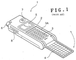
- Fig. 1 shows a prior-art portable telephone equipped with such a cover for the operating part.
- an operating part 3 provided with telephone number input keys and various function buttons, is disposed at the lower-half portion of the front face of a main casing 2 of a portable telephone 1.
- This operating part 3 is disposed in a recessed part 3A formed in the main casing 2 so that when an opening/closing cover 4 is folded and closed, the front face of this opening/closing cover 4 will be flush with the front face of the main casing 2.
- the opening/closing cover 4 has its base end part pivotally supported on the lower end part of the main casing 2 and is thereby mounted to the main casing 2 in a manner enabling opening and closing.
- Fig. 1 denotes a display panel
- 6 denotes an antenna
- 7 denotes a speaker
- 8 denotes a switch or other form of operating lever.
- the opening/closing cover 4 is folded with respect to the main casing 2 and fitted inside the recessed part 3A of the main casing 2 so that the operating part 3, which is disposed in this recessed part 3A, is housed at the inner side and unexposed to the exterior.
- the opening/closing cover 4 is raised from the main casing 2 and opened so that the operating part 3 will be exposed to the exterior.
- Such a portable telephone 1, equipped with the opening/closing cover 4 that houses the operating part 3, has the advantage that, by disposing a microphone and a part of the function buttons at the opening/closing cover 4 side, the outer dimensions of the condition in which the opening/closing cover 4 is folded can be made more compact in comparison to a portable phone that is not equipped with an opening/closing cover, and since in the standby condition, the operating part 3 is housed at the inner side of the folded opening/closing cover 4 and is not exposed to the exterior, the input keys, etc. are protected and erroneous operation due to erroneous pressing of the operating part 3 is prevented.
- the operating part 3 is disposed within the recessed part 3A for housing the opening/closing cover 4 in the main casing 2, when the opening/closing cover 4 is opened, the operating part 3 is positioned at a position that is recessed from the front face of the main casing 2 and is made difficult to operate.
- the operability becomes poor due to the difference in the stroke of the fingers required for operation, since an offset is formed between the operating part 3 disposed on the main casing 2 and the operating part disposed on the opening/closing cover 4.
- the opening/closing cover extends to the outer side of the main casing when the opening/closing cover is opened, the outer shape of the portable phone during use becomes even larger, making the phone unfit for portable use.
- This invention has been made to resolve the above-described problems of portable telephones and other portable information terminals.
- This invention has also been made to solve the above-described problems of prior-art portable telephones with an opening/closing cover that houses the operating part.
- An object of this invention is to secure good operability in a portable telephone equipped with an opening/closing cover that houses the operating part.
- a portable telephone equipped with an opening/closing cover, which can be opened and closed and houses an operating part at the inner side, has an operating panel, which comprises the above mentioned operating part, and which is mounted to a main casing of the portable telephone in a manner enabling movement between a position at the front face side and a position at the inner side of the main casing, a moving part, which moves this operating panel between the position at the front face side and the position at the inner side of the main casing.
- the above mentioned operating panel is positioned at the position at the inner side of the main casing and is housed at the inner side of the opening/closing cover when the above mentioned opening/closing cover is at the closed position, and the operating panel is moved to the position at the front face side of the main casing by the moving part in accordance with the opening operation of the opening/closing cover when the opening/closing cover is opened so that the operating surface of the operating panel will be positioned at a position at which it will be substantially flush with the back face of the opening/closing cover that is positioned at the opened position.
- the operating panel when the opening/closing cover is closed as in the standby condition of the portable telephone, the operating panel is positioned at the position at the inner side of the main casing and is housed at the inner side of the opening/closing cover.
- the moving part is actuated by the opening operation of the opening/closing cover and the operating panel is moved from the position at the inner side to the position at the front face side of the main casing, and when the opening/closing cover is opened completely and is positioned at the opened position, the operating surface of the operating panel that has been moved by the moving part becomes substantially flush with the back face (the surface that becomes the front face when the opening/closing cover is at the opened position) of the opening/closing cover that is positioned at the opened position.
- the opening/closing cover of a portable telephone equipped with the opening/closing cover when the opening/closing cover of a portable telephone equipped with the opening/closing cover is opened, an offset does not form between the back face of the opening/closing cover at the opened position and the operating surface of the operating panel. Therefore even when a part of the operation part is disposed on the back face of the opening/closing cover, the operating part disposed at this opening/closing cover and the operating part of the operating panel can be operated by the same stroke of the fingers and good operability can thus be secured.
- a portable telephone has, in addition to the arrangement according to the first aspect of this invention, a characteristic that a part of the above mentioned operating part is disposed at the back face side of the above mentioned opening/closing cover.
- the outer shape of the portable telephone can thereby be made compact and good operability is secured by the operating part disposed on the opening/closing cover and the operating part of the operating panel being positioned substantially within the same plane.
- a portable telephone has, in addition to the arrangement according to the first aspect of this invention, the characteristic that the above mentioned moving part is a resilient member that is interposed between the operating panel and the main casing and urges the operating panel in the direction of the position at the front face side of the main casing, and when the opening/closing cover is opened, the operating panel is moved from the position at the inner side towards the position at the front face side of the main casing by being urged by the resilient member.
- a portable telephone has, in addition to the arrangement according to the first aspect of this invention, the characteristic that the above mentioned moving part is an arm member, which is provided on the opening/closing cover and, in accompaniment with the opening operation of the opening/closing cover, engages with the above mentioned operating panel to urge the operating panel in the direction of the position at the front face side of the main casing, and when the opening/closing cover is opened, the operating panel is moved from the position at the inner side towards the position at the front face side of the main casing by being urged by the arm member.
- the above mentioned moving part is an arm member, which is provided on the opening/closing cover and, in accompaniment with the opening operation of the opening/closing cover, engages with the above mentioned operating panel to urge the operating panel in the direction of the position at the front face side of the main casing, and when the opening/closing cover is opened, the operating panel is moved from the position at the inner side towards the position at the front face side of the main casing by being urged by the arm member.
- a portable telephone has, in addition to the arrangement according to the first aspect of this invention, the characteristic of being equipped with a movable member, which is mounted to the operating panel in a manner enabling movement relative to the operating panel and, by the urging force that accompanies the opening operation of the opening/closing cover, is moved in the direction of engaging with the main casing and becomes latched to the main casing to position the operating panel at the position at the front face side of the main casing.
- the urging force that is generated in accompaniment with this opening operation of the opening/closing cover is applied to the movable member and the movable member is moved in the direction of engaging with the main casing.
- the movable member becomes latched to the main casing and the operating panel is thereby positioned at the position at the front face side of the main casing at which it becomes substantially flush with the back face of the opening/closing cover that is at the opened position.
- a portable telephone has, in addition to the arrangement according to the fifth aspect of this invention, the characteristic that a disengaging member, which, when the urging force on said movable member is relieved, urges the engaged movable member in the direction of disengaging from the main casing, is provided at the part of the main casing with which the above mentioned movable member engages.
- the disengaging member urges the movable member in the direction opposite that when the opening/closing cover is opened and disengages the movable member from the main casing, thereby enabling the movement of the operating panel from the position at the front face side towards the position at the inner side of the main casing.
- a portable telephone has, in addition to the arrangement according to the first aspect of this invention, the characteristic that the above mentioned main casing is equipped with an opened/closed condition detection part, which detects that the opening/closing cover is opened and thereupon sets the above mentioned operating part in the condition that enables operation. Since the operation of the operating part is thereby enabled when the opening/closing cover is opened and the operation of the operating part is disabled when the opening/closing cover is closed, erroneous operation is prevented and saving of power is achieved.
- a portable telephone has, in addition to the arrangement according to the first aspect of this invention, the characteristic that the above mentioned opening/closing cover is mounted to the main casing at a position such that the opening direction will be at the display panel side of the portable telephone.
- the enlargement of the outer shape of the portable telephone when the opening/closing cover is opened can thereby be prevented.
- Another object of this invention is to provide in a portable information terminal equipped with an opening/closing cover, a portable information terminal with which the outer shape will not become large even when the opening/closing cover is opened and yet with which good operability and convenience are secured.
- a portable information terminal equipped with an opening/closing cover, which can be opened and closed and houses an operating part at the inner side, and a display part, which displays images
- an opened/closed condition detection part which detects the opening/closing of the above mentioned opening/closing cover
- an image display part which outputs image signals to the above mentioned display part to make images be displayed on the display part
- the input of an opened/closed condition detection signal from the above mentioned opened/closed condition detection part performs, in accordance with the input of the opened/closed condition detection signal, predetermined forms of signal processing on the image signals to be output to the display part and makes images be displayed on the display part in accordance with the signal processed image signals.
- the portable information terminal is equipped with a display part, on which is displayed telephone numbers, electronic mail, and other images, and an opening/closing cover, which can be opened and closed and houses and protects an operating part, for inputting telephone numbers and performing other forms of information processing, at the inner side when the operating part is not used.
- the opening/closing cover is opened so that the operating part will be exposed to the exterior.
- That the opening/closing cover has been opened is detected by the opened/closed condition detection part, and when the opened/closed condition detection signal is input into the image display part from the opened/closed condition detection part, the image display part performs the required signal processes on the image signals to be output to the display part to make the display part display images and changes the images displayed on the display part to the required forms.
- the image displayed on the display part is compressed and changed to a form with which the entirety of the image can be seen, or an image displayed on the display part is changed to a form with which the image can be scrolled in the required direction so that the necessary parts of the image will not be hidden by the opening/closing cover, or the image displayed on the display part is changed to a form with which a required part of the image is moved to a required position of the display part so that it will not be hidden by the opening/closing cover.
- the opening/closing cover can thus be mounted at a position at which it will overlap with the display part when at the opened position, the opened opening/closing cover can be prevented from being extended from the outer edge part of the portable information terminal and enlarging the outer shape of the portable information terminal.
- a portable information terminal has, in addition to the arrangement according to the ninth aspect of this invention, the characteristic that when an opened/closed condition detection signal that indicates that the opening/closing cover has been opened is input from the opened/closed condition detection part, the above mentioned image display part applies to the image signals a signal process that compresses the image displayed on the display part.
- the compressed image will be displayed at a portion of the display part that is not overlapped with the opening/closing cover at the opened position, thereby securing the operability and convenience of the portable information terminal.
- a portable information terminal has, in addition to the arrangement according to the tenth aspect of this invention, the characteristic that the above mentioned signal process of compressing the image is a signal process that decreases the scanning lines for image display, and a compressed image is thereby displayed on the display part.
- a portable information terminal has, in addition to the arrangement according to the tenth aspect of this invention, the characteristic that when an opened/closed condition detection signal that indicates that the opening/closing cover has been closed is input from the opened/closed condition detection part, the above mentioned image display part applies to the image signals a signal process that returns the compressed image displayed on the display part to the original size.
- the original image can thus be made to be displayed on the entirety of the display part when the opening/closing cover becomes closed and operation using the operating part is not performed.
- a portable information terminal has, in addition to the arrangement according to the tenth aspect of this invention, the characteristics that the above mentioned opening/closing cover is disposed at a position at which it will overlap with the above mentioned display part when at the opened position and the above mentioned image display part applies to the image signals a signal process that makes a compressed image be displayed on a portion of the display part that will not be overlapped with the opening/closing cover at the opened position.
- a portable information terminal has, in addition to the arrangement according to the ninth aspect of this invention, the characteristic that when an opened/closed condition detection signal that indicates that the opening/closing cover has been opened is input from the opened/closed condition detection part, the above mentioned image display part applies to the image signals a signal process that scrolls the image displayed on the display part in a required direction.
- the compressed image will be scrolled in a required direction so that the image of the necessary portion will be displayed at a portion of the display part that is not overlapped with the opening/closing cover at the opened position. The operability and convenience of the portable information terminal can thus be secured.
- a portable information terminal has, in addition to the arrangement according to the fourteenth aspect of this invention, the characteristic that when an opened/closed condition detection signal that indicates that the opening/closing cover has been closed is input from the opened/closed condition detection part, the above mentioned image display part applies to the image signals a signal process that scrolls the image, which is displayed on the display part and is at the scrolled position, back to the original position.
- the original image can thus be made to be displayed on the entirety of the display part when the opening/closing cover becomes closed and operation using the operating part is not performed.
- a portable information terminal has, in addition to the arrangement according to the fourteenth aspect of this invention, the characteristics that the above mentioned opening/closing cover is disposed at a position at which it will overlap with the above mentioned display part when at the opened position and the above mentioned image display part applies to the image signals a signal process that scrolls the image towards a portion of the display part that will not be overlapped with the opening/closing cover at the opened position. Since the scrolled part of the image that is necessary for operation, etc.
- the opened opening/closing cover can be mounted at a position at which it will overlap with the display part at the opened position, the opened opening/closing cover can be prevented from being extended from the outer edge of the portable information terminal and enlarging the outer shape of the portable information terminal.
- a portable information terminal has, in addition to the arrangement according to the nineth aspect of this invention, the characteristic that when an opened/closed condition detection signal that indicates that the opening/closing cover has been opened is input from the opened/closed condition detection part, the above mentioned image display part applies to the image signals a signal process that moves an arbitrary image selected from the image displayed on the display part to a required position.
- the image of the necessary portion of the image displayed will be moved to a portion of the display part that is not overlapped with the opening/closing cover at the opened position. The operability and convenience of the portable information terminal can thus be secured.
- a portable information terminal has, in addition to the arrangement according to the seventeenth aspect of this invention, the characteristic that the above mentioned selection of the image to be moved is performed by the detection of the touched position of a touch panel mounted to the display part. A user can thus select the image portion to be moved and make this image portion be moved to the required position of the display part when the opening/closing cover is opened, simply by touching the portion of the touch panel, mounted to the display part, that corresponds to the position at which the desired image is displayed.
- a portable information terminal has, in addition to the arrangement according to the seventeenth aspect of this invention, the characteristic that when an opened/closed condition detection signal that indicates that the opening/closing cover has been closed is input from the opened/closed condition detection part, the above mentioned image display part applies to the image signals a signal process that moves the selected image, which is at the moved position in the display part, back to the original position.
- the moved image can thus be made to be displayed at the original position of the display part when the opening/closing cover becomes closed and operation using the operating part is not performed.
- a portable information terminal has, in addition to the arrangement according to the seventeenth aspect of this invention, the characteristics that the above mentioned opening/closing cover is disposed at a position at which it will overlap with the above mentioned display part when at the opened position and the above mentioned image display part applies to the image signals a signal process that moves a selected image to a position of the display part that will not be overlapped with the opening/closing cover at the opened position.
- the image which is the part of the image, displayed on the display part, that is necessary for operation, etc.
- the operability and convenience of the portable information terminal will be secured, and since the opening/closing cover can be mounted at a position at which it will overlap with the display part at the opened position, the opened opening/closing cover can be prevented from being extended from the outer edge of the portable information terminal and enlarging the outer shape of the portable information terminal.
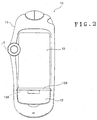
- Fig. 2 is a front view, which shows a portable telephone equipped with cover opening/closing mechanism by this invention in the standby condition
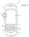
- Fig. 3 is a front view, which shows this portable telephone in the operated condition.
- a portable telephone 10 has a display panel 12 disposed at the central part of the surface of a main casing 11, and an opening/closing cover 13 is mounted to the lower part of this display panel 12.
- the opening/closing cover 13 has its upper end part (the right end part in Fig. 4) mounted by a parallel shaft 13A to the bottom edge (the left edge in Fig. 4) of the display panel 12 in a manner enabling rotation in the vertical direction (left/right direction in Fig. 4) with respect to the main casing 11.
- the position of the opening/closing cover 13 is set so that when the opening/closing cover 13 is at the closed position with respect to the main casing 11, the surface will be substantially flush with the surface of the main casing 11, and the position of the display panel 12 is set so that it will be positioned to the inner side of the main casing 11 substantially by just the thickness of the opening/closing cover 13.
- the opening/closing cover 13 has an integrally formed arm part 13B, which, in the condition where the opening/closing cover 13 is at the closed position with respect to the main casing 11, extends from the position of shaft 13A to the side of the display panel 12.
- the upper edge (the right edge in Fig. 4) of this arm part 13B is positioned just at the same position as the lower edge (the left edge in Fig. 4) of the display panel 12 so that when the portable telephone 10 is viewed from the front, a gap cannot be seen between the display panel 12 and the arm part 13B.
- An inclined surface 13Ba which is inclined downwards (leftwards in Fig. 3) from the front face to the back face is formed on the front end part of the arm part 13B.
- An operating panel 14 is fitted in a manner enabling rising and lowering onto the portion of the main casing 11 that is covered by the opening/closing cover 13, and at the back face side of this operating panel 14, an ascending/descending support plate 15 is joined to the operating panel 14 in a manner that does not allow separation but enables sliding in the vertical direction (left/right direction in Fig. 4) by the fitting of unillustrated fitting grooves formed on the mutual joining surfaces.
- First operating buttons K1 such as telephone number input keys, function keys, etc., are disposed on the front face of the operating panel 14 and second operating buttons K2 are disposed on the back face side of the opening/closing cover 13.
- a compression spring 16 is interposed between the back face of the ascending/descending support plate 15 and a frame part 11A, which is formed in an integral manner on the inner side of the main casing 11, and this compression spring 16 urges the ascending/descending support plate 15 and the operating panel 14 towards the front face side of the main casing 11.
- An inclined surface 15a which is inclined downwards (leftwards in Fig. 4) from the front face to the back face, is formed on the upper end part of the ascending/descending support plate 15.
- a recessed part 11Aa into which the ascending/descending support plate 15 in the raised position fits upon sliding in the downward direction (leftward direction in Fig. 4) of the main casing 11, is formed on frame part 11A of main casing 11.
- a spring 17 which is compressed by the entering ascending/descending support plate 15, and an unillustrated opened/closed condition detection switch, which, by being pressed and turned on by the further entry of the ascending/descending support plate 15, conducts power to the first operating buttons K1 disposed on the operating panel 14 and the second operating buttons K2 disposed on the opening/closing cover 13 to enable their operation.
- Figs. 2 and 3 19 denotes an operating dial for performing the operation of switching the display screen, etc. of the display panel 12.
- the opening/closing cover 13 is closed so as to cover the operating panel 14 as shown in Fig. 2 and is latched to the main casing 11 by the engagement of an unillustrated engaging part.
- the opening/closing cover 13 is opened by rotating it about the shaft 13A in the upward direction with respect to the main casing 11 so that the operating panel 14 will be exposed as shown in Fig. 3.
- the arm part 13B which rotates and enters inside the main casing 11 in accompaniment with the upward (rightward in Fig. 5) rotation of the opening/closing cover 13 about the shaft 13A, comes in contact with the upper end parts (right end parts in Fig. 5) of the operating panel 14 and the ascending/descending support plate 15 from below.
- the arm part 13B then supportingly raises the upper end parts of the operating panel 14 and the ascending/descending support plate 15 in accompaniment with this rotation of the opening/closing cover 13, and the ascending/descending support plate 15 becomes urged in the downward direction (leftward direction in Fig. 5) of the main casing 11 by the sliding of the inclined surface 13Ba of the arm part 13B against the inclined surface 15a of the ascending/descending support plate 15.
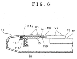
- the opening/closing cover 13 becomes completely opened as shown in Fig. 6, the opening/closing cover 13 becomes positioned at a position on the display panel 12 where the back face (operating surface) on which the second operating buttons K2 are disposed will be substantially flush with the front face of the main casing 11.
- the lower end part (left end part in Fig. 6) of the ascending/descending support plate 15 becomes fitted into the recessed part 11Aa, formed on frame part 11A of the main casing 11, while compressing the spring 17, and the ascending/descending support plate 15 and the operating panel 14, which is joined to the ascending/descending support plate 15 in an inseparable manner, become latched to the main casing 11 and thereby prevented from rising further.
- the operating panel 14 is positioned at a position at which the front side operating surface on which the first operating buttons K1 are disposed will be substantially flush with the front face of the main casing 11.
- the operating panel 14 is raised and the operating surface, on which the first operating buttons K1 are disposed, and the operating surface (back face) of the opening/closing cover 13, on which the second operating buttons K2 are disposed, become aligned in substantially the same plane.
- the unillustrated opened/closed condition detection switch mounted inside recessed part 11Aa, comes in contact with the end part of the ascending/descending support plate 15 that has been fitted inside this recessed part 11Aa and is thereby turned on to conduct power and thus enable operation by first operating buttons K1 and second operating buttons K2.
- the opening/closing cover 13 then becomes latched to the main casing 11 by means of an unillustrated engaging part and, as shown in Fig. 2, the operating surface of the operating panel 14 becomes completely housed at the inner side of the opening/closing cover 13 so as to become unable to be seen from the outer side.
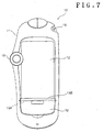
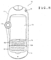
- Fig. 7 is a front view, which shows another embodiment of a portable telephone by this invention in the standby condition and Fig. 8 is a front view, which shows this portable telephone in the operating condition.
- the portable telephone 10 has the display panel 12 disposed at the central part of the surface of the main casing 11, and an the opening/closing cover 13 is mounted to the lower part of this display panel 12.
- This opening/closing cover 13 is mounted in a manner enabling rotation in the vertical direction with respect to the main casing 11 by a shaft 13A, which is parallel to the lower edge of the display panel 12.
- the operating panel 14 is mounted at a portion of the main casing 11 that is covered by the opening/closing cover 13, and as shown in Fig. 8, first operating keys K1, such as telephone number input keys, function keys, etc., are disposed on the front face of this operating panel 14 and second operating keys K2 are disposed on the back face (the surface that becomes the front side in the opened condition) of the opening/closing cover 13.
- first operating keys K1 such as telephone number input keys, function keys, etc.
- Figs. 7 and 8 18 denotes a CCD camera and 19 denotes a jog dial for performing operations, such as the switching of the display screen of the display panel 12, etc.
- Fig. 9 is a block diagram, which shows an example of the arrangement of the control unit of this portable telephone 10.
- a sending/receiving circuit 21, a data processing circuit 22, which performs clock control of the image signals and audio signals received by the sending/receiving circuit 21 and functions as an interface with a below-described CPU, and a DSP (Digital Signal Processor) 23, which is a high-speed arithmetic processing type microprocessor, are connected successively to an antenna 20 mounted to the main casing 11 of the portable telephone 10.
- DSP Digital Signal Processor
- An audio coder/decoder 24 is connected to the DSP 23, a microphone 25 and a ringer 26 are connected to the audio coder/decoder 24, and furthermore, a speaker 29 is connected to the coder/decoder 24 via a modulating sending circuit 27 and a receiving demodulating circuit 28.
- a CPU 30 is connected to the data processing circuit 22 and the DSP 23.
- the display panel 12 is connected via an LCD driver 31
- a CCD camera 18 is connected via a signal processing circuit 32
- an opened/closed condition detection sensor 33 which is mounted to the opening/closing part of the opening/closing cover 13 and detects the opened/closed condition of the opening/closing cover 13, and a touch panel 34, mounted to the display panel 12, are connected
- a connector 35 which is connected to a personal computer, etc. for performing transaction of various data with the personal computer etc., is connected via an external I/F 36.
- an SRAM 37 in which are stored various personal data, such as the shortcut dial numbers, etc. input by a user
- a ROM 38 in which the various control programs of the portable telephone are stored
- first operation keys K1 and second operation keys K2 which include various operating keys, such as the function keys and numerical keys for input of telephone numbers, and the jog dial 19.
- a radio wave that is received by the sending/receiving circuit 21 via the antenna 20 is separated into image signals and audio signals at the subsequent data processing circuit 22, and while being subject to the respective clock control based on instructions from the CPU 30, the image signals are output to the CPU 30 and the audio signals are output to the DSP 23.
- the audio signals that are input into the DSP 23 undergo audio processing at the DSP 23, are then input into and D/A converted by the audio coder/decoder 24, and output via the modulating sending circuit 27 and the receiving demodulating circuit 28 to the speaker 29 or the ringer 26.
- Audio signals input from the microphone 25 are A/D converted by the audio coder/decoder 24 and are then transmitted from the antenna 20 via the DSP 23, the data processing circuit 22, and the sending/receiving circuit 21.
- the CPU 30 supervises the control of the operations of the data processing circuit 22, DSP 23, LCD driver 31, etc. by means of the various portable telephone control programs that are stored in the ROM 38.
- the CPU 30 reads out, from the ROM 38, the control program corresponding to the operation signal, and based on the control program that has been read out, outputs image data for the operating screen onto the LCD driver 31 to make the operating screen be displayed on the display panel 12 and performs operation control of the data processing circuit 22 and the DSP 23 and the writing of data into or reading of data from the SRAM 37 or transaction, etc. of data with a personal computer, etc. which is connected by the connector 35.
- the CPU 30 outputs the corresponding image data read out from the ROM 38 to the LCD driver 31 and performs switching of the screen displayed on the display panel 12.
- the opening/closing cover 13 is arranged to open upwards and become unfolded over the display panel 12, the lower portion of the display panel 12 becomes hidden by the opening/closing cover 13 in the opened condition. There is thus a problem that a part of the screen displayed on the display panel 12 cannot be viewed as it is.
- the portable telephone 10 thus has a below-described screen processing program equipped in the abovementioned ROM 38 of the control unit, and when the opening of the opening/closing cover 13 is detected by the opened/closed condition detection sensor 33, the CPU 30 performs such processes as those described below based on the screen processing program read out from the ROM 38 so that the entirety or the necessary part of the screen displayed on the display panel 12 can be viewed.
- the CPU 30, based on the detection signal input from the opened/closed condition detection sensor 33, performs signal processing of the image signal output to the LCD driver 31 so that the image displayed on the display panel 12 will have the form of the image G1', which is shown in Fig. 10B and is compressed in the upper direction in comparison to the image G1, shown in Fig. 10A that is displayed when the opening/closing cover 13 is closed.
- the part of the screen that becomes hidden when the opening/closing cover 13 is opened thus becomes a blank b and the hiding of the image displayed on the display panel 12 by the opening/closing cover 3 is avoided.
- This compression of the image is performed for example by decreasing (thinning) the number of scan lines of image G1 in correspondence to the number of pixels in the vertical direction of the display space of the display panel 12 in which the compressed image is to be displayed.
- the CPU 30 based on the detection signal input from the opened/closed condition detection sensor 33, recovers the original image G1, shown in Fig. 10A, from the compressed image G1' of Fig. 10B, which had been displayed on the display panel 12.
- the CPU 30 upon input of a detection signal indicating the detection of the opening of the opening/closing cover 13 from the opened/closed condition detection sensor 33, scrolls the image G1 in the upward direction so that the partial image G1" within the image G1, which contains the image of A, will be displayed on the display panel 12 as shown in Fig. 11B.
- the CPU 30 based on the detection signal input from the opened/closed condition detection sensor 33, returns the image G1" of Fig. 11B, which was displayed at the scrolled position on the display panel 12, to the original position of image G1 of Fig. 11A.
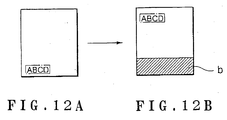
- a desired text or image displayed on the display panel 12 is to be kept visible, that is for example, if an image captured by the CCD camera 18 or a photograph or text, etc. (the characters "ABCD" in the example illustrated in Fig. 12) that was sent from another terminal device is displayed on the part of the display panel 12 that will become hidden when the opening/closing cover 13 is opened as shown in Fig. 12A and this photograph or text, etc. is to be made visible even when the opening/closing cover 13 has been opened, the user of the portable telephone 10 touches the photograph or text, etc. (in this case, the characters "ABCD"), which is to be made visible even when the opening/closing cover 13 is opened, before opening the opening/closing cover 13.
- the touched position on the display panel 12, that is, the position at which the desired photograph or text is displayed is detected by the touch panel 34 (see Fig. 9) mounted to the display panel 12, and based on the touched position detection signal input from this touch panel 34, the CPU 30, upon input of the detection signal indicating the detection of the opening of opening/cover 13 by the opened/closed condition detection sensor 33, moves the photograph or text, etc. (in this case, the characters "ABCD") at the position indicated by the touched position detection signal to a part of the display panel 12 that will not be hidden by the opening/closing cover 13 when the opening/closing cover 13 is opened as shown in Fig. 12B.
- the CPU 30 based on the detection signal input from the opened/closed condition detection sensor 33, moves the text of Fig. 12B, which is displayed on the display panel 12 at the moved position, back to the original position of Fig. 12A.
Landscapes
- Engineering & Computer Science (AREA)
- Signal Processing (AREA)
- Telephone Set Structure (AREA)
Applications Claiming Priority (4)
| Application Number | Priority Date | Filing Date | Title |
|---|---|---|---|
| JP2000169132 | 2000-06-06 | ||
| JP2000169132A JP3907388B2 (ja) | 2000-06-06 | 2000-06-06 | 携帯電話機 |
| JP2000176617 | 2000-06-13 | ||
| JP2000176617A JP3942808B2 (ja) | 2000-06-13 | 2000-06-13 | 携帯情報端末機 |
Publications (3)
| Publication Number | Publication Date |
|---|---|
| EP1162811A2 true EP1162811A2 (fr) | 2001-12-12 |
| EP1162811A3 EP1162811A3 (fr) | 2004-06-30 |
| EP1162811B1 EP1162811B1 (fr) | 2006-12-06 |
Family
ID=26593411
Family Applications (1)
| Application Number | Title | Priority Date | Filing Date |
|---|---|---|---|
| EP01113753A Expired - Lifetime EP1162811B1 (fr) | 2000-06-06 | 2001-06-05 | Téléphone portable |
Country Status (4)
| Country | Link |
|---|---|
| US (1) | US6807276B2 (fr) |
| EP (1) | EP1162811B1 (fr) |
| CN (1) | CN1206813C (fr) |
| DE (1) | DE60124983T2 (fr) |
Cited By (2)
| Publication number | Priority date | Publication date | Assignee | Title |
|---|---|---|---|---|
| WO2004109494A1 (fr) | 2003-06-05 | 2004-12-16 | Nokia Corporation | Procede et application logicielle permettant de transmettre, a l'utilisateur d'un dispositif de traitement de donnees, des informations se trouvant derriere un obstacle place sur l'affichage |
| EP1667408A1 (fr) * | 2004-12-03 | 2006-06-07 | Samsung Electronics Co., Ltd. | Terminal portable de type coulissant avec clavier ressortant |
Families Citing this family (14)
| Publication number | Priority date | Publication date | Assignee | Title |
|---|---|---|---|---|
| JP3606498B2 (ja) * | 1996-04-26 | 2005-01-05 | 三菱電機株式会社 | 携帯情報端末装置 |
| KR100396271B1 (ko) * | 2001-08-23 | 2003-09-02 | 삼성전자주식회사 | 자동 및 수동 겸용 접이형 휴대용 무선단말기 |
| JP3979090B2 (ja) * | 2001-12-28 | 2007-09-19 | 日本電気株式会社 | カメラ付き携帯型電子機器 |
| USD482010S1 (en) | 2002-05-20 | 2003-11-11 | Nokia Corporation | Handset |
| JP3726070B2 (ja) * | 2002-05-28 | 2005-12-14 | Necアクセステクニカ株式会社 | 携帯無線端末 |
| US20040204000A1 (en) * | 2002-05-30 | 2004-10-14 | Aaron Dietrich | Mobile communication device including an array sensor |
| US7085542B2 (en) * | 2002-05-30 | 2006-08-01 | Motorola, Inc. | Portable device including a replaceable cover |
| US6879842B2 (en) * | 2002-05-31 | 2005-04-12 | Lavaflow, Llp | Foldable wireless communication device functioning as a cellular telephone and a personal digital assistant |
| US7010333B2 (en) * | 2003-02-19 | 2006-03-07 | Sony Ericsson Mobile Communications Ab | Radiotelephone terminal with dual-sided keypad apparatus |
| CN101645719A (zh) * | 2008-08-07 | 2010-02-10 | 深圳富泰宏精密工业有限公司 | 便携式个人终端及其图标设定方法 |
| TWI365058B (en) * | 2009-07-23 | 2012-06-01 | Top Victory Invest Ltd | Digital photo frame with slide structure |
| US20120081275A1 (en) * | 2010-10-05 | 2012-04-05 | Microsoft Corporation | Media Display Device |
| CN103544676B (zh) * | 2012-07-16 | 2016-12-28 | 联想(北京)有限公司 | 图像处理方法及电子设备 |
| WO2021082007A1 (fr) * | 2019-11-01 | 2021-05-06 | 深圳市汇顶科技股份有限公司 | Procédé de détection de couvercle d'ouverture/de fermeture de dispositif, dispositif de commande tactile, pavé tactile et dispositif électronique |
Family Cites Families (6)
| Publication number | Priority date | Publication date | Assignee | Title |
|---|---|---|---|---|
| JPH04281628A (ja) * | 1991-03-11 | 1992-10-07 | Matsushita Electric Ind Co Ltd | 携帯形無線機 |
| US5519569A (en) | 1994-06-30 | 1996-05-21 | Compaq Computer Corporation | Compact notebook computer having a foldable and collapsible keyboard structure |
| JP3606498B2 (ja) * | 1996-04-26 | 2005-01-05 | 三菱電機株式会社 | 携帯情報端末装置 |
| CN1113519C (zh) | 1997-10-01 | 2003-07-02 | 日本电气株式会社 | 便携无线电通信装置 |
| US6038313A (en) | 1997-11-20 | 2000-03-14 | Nortel Networks Corporation | Double sided keyboard for a telephone |
| FI114267B (fi) | 1998-01-29 | 2004-09-15 | Nokia Corp | Elektroninen laite ja menetelmä tietojen näyttämiseksi |
-
2001
- 2001-06-04 US US09/871,702 patent/US6807276B2/en not_active Expired - Fee Related
- 2001-06-05 EP EP01113753A patent/EP1162811B1/fr not_active Expired - Lifetime
- 2001-06-05 DE DE60124983T patent/DE60124983T2/de not_active Expired - Fee Related
- 2001-06-06 CN CN01115751.8A patent/CN1206813C/zh not_active Expired - Fee Related
Cited By (4)
| Publication number | Priority date | Publication date | Assignee | Title |
|---|---|---|---|---|
| WO2004109494A1 (fr) | 2003-06-05 | 2004-12-16 | Nokia Corporation | Procede et application logicielle permettant de transmettre, a l'utilisateur d'un dispositif de traitement de donnees, des informations se trouvant derriere un obstacle place sur l'affichage |
| EP1629371A1 (fr) * | 2003-06-05 | 2006-03-01 | Nokia Corporation | Procede et application logicielle permettant de transmettre, a l'utilisateur d'un dispositif de traitement de donnees, des informations se trouvant derriere un obstacle place sur l'affichage |
| US7710390B2 (en) | 2003-06-05 | 2010-05-04 | Nokia Corporation | Method and software application for transmitting information remaining behind an obstacle located in front of the display to the user of a data processing device |
| EP1667408A1 (fr) * | 2004-12-03 | 2006-06-07 | Samsung Electronics Co., Ltd. | Terminal portable de type coulissant avec clavier ressortant |
Also Published As
| Publication number | Publication date |
|---|---|
| CN1206813C (zh) | 2005-06-15 |
| EP1162811B1 (fr) | 2006-12-06 |
| US20020018558A1 (en) | 2002-02-14 |
| DE60124983D1 (de) | 2007-01-18 |
| CN1332525A (zh) | 2002-01-23 |
| EP1162811A3 (fr) | 2004-06-30 |
| US6807276B2 (en) | 2004-10-19 |
| DE60124983T2 (de) | 2007-06-14 |
Similar Documents
| Publication | Publication Date | Title |
|---|---|---|
| US6807276B2 (en) | Portable telephone | |
| US7418275B2 (en) | Mobile communication apparatus with rotatable display screen | |
| CN100579139C (zh) | 便携式电子设备 | |
| JP4927791B2 (ja) | 携帯端末装置 | |
| US7493151B2 (en) | Housing arrangement for a portable device with a display | |
| US20060135226A1 (en) | Mobile communication terminal for changing operation mode based on opening direction of folder cover and method thereof | |
| US20050148375A1 (en) | Apparatus for mobile terminal display | |
| CN100499691C (zh) | 用于便携式电子设备的小键盘 | |
| JPH1169214A (ja) | 情報通信端末装置 | |
| US8126513B2 (en) | Information processing apparatus | |
| JP2003319044A (ja) | 携帯電話機 | |
| JP2004312389A (ja) | 携帯通信端末装置 | |
| US20040235540A1 (en) | Portable terminal unit | |
| US20050282594A1 (en) | Communication device including one or more electrical control buttons in an upper housing part | |
| JP2001024762A (ja) | 携帯電話機 | |
| JP4600121B2 (ja) | 折り畳み型携帯電話機 | |
| JP3942808B2 (ja) | 携帯情報端末機 | |
| KR100640402B1 (ko) | 입력 인터페이스 모드에 따라 전자 터치 인터페이스들을화면과 별도의 영역에 가변적으로 표시할 수 있는 휴대용단말기 | |
| CN1371567A (zh) | 便携式电话 | |
| CN1794845B (zh) | 改变操作模式的移动通信终端及其方法 | |
| JP2004112392A (ja) | 携帯通信端末並びにそのキーの機能割り当て方法をコンピュータに実行させるプログラム | |
| JP2003143284A (ja) | 携帯端末 | |
| JP2004297648A (ja) | 携帯電話機並びにそのメニュー表示をコンピュータに実行させるプログラム | |
| KR200323861Y1 (ko) | 슬라이딩 커버를 구비하는 듀얼폴더 휴대전화 | |
| JP2006197093A (ja) | 携帯情報端末 |
Legal Events
| Date | Code | Title | Description |
|---|---|---|---|
| PUAI | Public reference made under article 153(3) epc to a published international application that has entered the european phase |
Free format text: ORIGINAL CODE: 0009012 |
|
| AK | Designated contracting states |
Kind code of ref document: A2 Designated state(s): AT BE CH CY DE DK ES FI FR GB GR IE IT LI LU MC NL PT SE TR |
|
| AX | Request for extension of the european patent |
Free format text: AL;LT;LV;MK;RO;SI |
|
| RIC1 | Information provided on ipc code assigned before grant |
Ipc: 7G 06F 3/033 B Ipc: 7H 04M 1/247 B Ipc: 7G 06F 1/16 B Ipc: 7G 06F 3/02 B Ipc: 7H 04M 1/02 A |
|
| PUAL | Search report despatched |
Free format text: ORIGINAL CODE: 0009013 |
|
| AK | Designated contracting states |
Kind code of ref document: A3 Designated state(s): AT BE CH CY DE DK ES FI FR GB GR IE IT LI LU MC NL PT SE TR |
|
| AX | Request for extension of the european patent |
Extension state: AL LT LV MK RO SI |
|
| 17P | Request for examination filed |
Effective date: 20040624 |
|
| 17Q | First examination report despatched |
Effective date: 20040809 |
|
| AKX | Designation fees paid |
Designated state(s): DE FR GB |
|
| GRAP | Despatch of communication of intention to grant a patent |
Free format text: ORIGINAL CODE: EPIDOSNIGR1 |
|
| RAP1 | Party data changed (applicant data changed or rights of an application transferred) |
Owner name: PIONEER DESIGN CORPORATION Owner name: PIONEER CORPORATION |
|
| GRAS | Grant fee paid |
Free format text: ORIGINAL CODE: EPIDOSNIGR3 |
|
| GRAA | (expected) grant |
Free format text: ORIGINAL CODE: 0009210 |
|
| AK | Designated contracting states |
Kind code of ref document: B1 Designated state(s): DE FR GB |
|
| REG | Reference to a national code |
Ref country code: GB Ref legal event code: FG4D |
|
| REF | Corresponds to: |
Ref document number: 60124983 Country of ref document: DE Date of ref document: 20070118 Kind code of ref document: P |
|
| ET | Fr: translation filed | ||
| REG | Reference to a national code |
Ref country code: GB Ref legal event code: 746 Effective date: 20070524 |
|
| PGFP | Annual fee paid to national office [announced via postgrant information from national office to epo] |
Ref country code: DE Payment date: 20070831 Year of fee payment: 7 |
|
| PLBE | No opposition filed within time limit |
Free format text: ORIGINAL CODE: 0009261 |
|
| STAA | Information on the status of an ep patent application or granted ep patent |
Free format text: STATUS: NO OPPOSITION FILED WITHIN TIME LIMIT |
|
| 26N | No opposition filed |
Effective date: 20070907 |
|
| PGFP | Annual fee paid to national office [announced via postgrant information from national office to epo] |
Ref country code: GB Payment date: 20070629 Year of fee payment: 7 |
|
| PGFP | Annual fee paid to national office [announced via postgrant information from national office to epo] |
Ref country code: FR Payment date: 20070615 Year of fee payment: 7 |
|
| GBPC | Gb: european patent ceased through non-payment of renewal fee |
Effective date: 20080605 |
|
| REG | Reference to a national code |
Ref country code: FR Ref legal event code: ST Effective date: 20090228 |
|
| PG25 | Lapsed in a contracting state [announced via postgrant information from national office to epo] |
Ref country code: DE Free format text: LAPSE BECAUSE OF NON-PAYMENT OF DUE FEES Effective date: 20090101 |
|
| PG25 | Lapsed in a contracting state [announced via postgrant information from national office to epo] |
Ref country code: GB Free format text: LAPSE BECAUSE OF NON-PAYMENT OF DUE FEES Effective date: 20080605 |
|
| PG25 | Lapsed in a contracting state [announced via postgrant information from national office to epo] |
Ref country code: FR Free format text: LAPSE BECAUSE OF NON-PAYMENT OF DUE FEES Effective date: 20080630 |