EP1163388B2 - Machine a laver a chargement frontal - Google Patents
Machine a laver a chargement frontal Download PDFInfo
- Publication number
- EP1163388B2 EP1163388B2 EP00912592A EP00912592A EP1163388B2 EP 1163388 B2 EP1163388 B2 EP 1163388B2 EP 00912592 A EP00912592 A EP 00912592A EP 00912592 A EP00912592 A EP 00912592A EP 1163388 B2 EP1163388 B2 EP 1163388B2
- Authority
- EP
- European Patent Office
- Prior art keywords
- motor
- rear wall
- washing machine
- shaft
- machine according
- Prior art date
- Legal status (The legal status is an assumption and is not a legal conclusion. Google has not performed a legal analysis and makes no representation as to the accuracy of the status listed.)
- Expired - Lifetime
Links
- 238000005406 washing Methods 0.000 title claims abstract description 28
- 230000005540 biological transmission Effects 0.000 claims description 7
- 238000003475 lamination Methods 0.000 claims 2
- 101150114468 TUB1 gene Proteins 0.000 description 9
- 230000033001 locomotion Effects 0.000 description 3
- 238000010276 construction Methods 0.000 description 2
- 239000000463 material Substances 0.000 description 2
- 238000011161 development Methods 0.000 description 1
- 230000018109 developmental process Effects 0.000 description 1
- ZINJLDJMHCUBIP-UHFFFAOYSA-N ethametsulfuron-methyl Chemical compound CCOC1=NC(NC)=NC(NC(=O)NS(=O)(=O)C=2C(=CC=CC=2)C(=O)OC)=N1 ZINJLDJMHCUBIP-UHFFFAOYSA-N 0.000 description 1
- 230000005284 excitation Effects 0.000 description 1
- 239000002245 particle Substances 0.000 description 1
- 230000035515 penetration Effects 0.000 description 1
- 230000002787 reinforcement Effects 0.000 description 1
- 230000002940 repellent Effects 0.000 description 1
- 239000005871 repellent Substances 0.000 description 1
- 230000000284 resting effect Effects 0.000 description 1
- 238000004804 winding Methods 0.000 description 1
Images

Classifications
-
- H—ELECTRICITY
- H02—GENERATION; CONVERSION OR DISTRIBUTION OF ELECTRIC POWER
- H02K—DYNAMO-ELECTRIC MACHINES
- H02K7/00—Arrangements for handling mechanical energy structurally associated with dynamo-electric machines, e.g. structural association with mechanical driving motors or auxiliary dynamo-electric machines
- H02K7/10—Structural association with clutches, brakes, gears, pulleys or mechanical starters
- H02K7/1004—Structural association with clutches, brakes, gears, pulleys or mechanical starters with pulleys
-
- D—TEXTILES; PAPER
- D06—TREATMENT OF TEXTILES OR THE LIKE; LAUNDERING; FLEXIBLE MATERIALS NOT OTHERWISE PROVIDED FOR
- D06F—LAUNDERING, DRYING, IRONING, PRESSING OR FOLDING TEXTILE ARTICLES
- D06F37/00—Details specific to washing machines covered by groups D06F21/00 - D06F25/00
- D06F37/30—Driving arrangements
- D06F37/304—Arrangements or adaptations of electric motors
Definitions
- the invention relates to one of the feedable washing machine with a within a standing with the rear wall of the tub in a fixed connection bearing sleeve over a shaft mounted laundry drum, which is driven by an arranged behind the rear wall of the tub motor.
- a DC external rotor motor for the direct drive of a laundry drum in a laundry machine is known, the rotor via a gear, for example in the manner of a planetary gear, drives the drive shaft of the laundry drum.
- a gear for example in the manner of a planetary gear
- An electric drive motor is known, which is attached via support arm to a vibrating housing and drives via transmission belt on a pulley of a tub.
- the GB 2 104 110 A shows a fixed outside the periphery of a tub drive motor.
- drive motors for driving stored in lye containers laundry drums known, which are arranged behind the rear wall of the tub, but are not connected to the rear wall of the tub.
- a particular advantage of the invention is that the laundry drum is driven by a motor having a lower torque compared to a direct drive.
- the reduction of the torque is achieved by a transmission, however, in contrast to a concentric with the drive shaft arranged motor and an associated likewise concentrically arranged gear, as shown in DE 39 27 426 A1 is known, leads to a reduction of the space for the drive.
- the lower material cost for the engine in contrast to direct drive motors in contrast to direct drive motors.
- the tolerances in the air gap can be better controlled than in direct drive, whereby the efficiency and the engine noise can be influenced favorably.
- the motor is arranged on the support member. This is formed by extending from the center formed by the drum shaft outwardly extending arms, wherein on one of the arms of the motor is arranged.
- the arm supporting the motor is circularly widened in the plane coplanar with the rear wall of the tub, so that the motor extends completely in the region of a support arm of the support part when viewed from above on the rear wall of the tub and of the support star.
- the support member preferably has a U-shaped from the rear wall of the tub weg umandes profile, through which it receives a higher rigidity. Preferably, this U-shaped profile also encloses the circular bulge in the arm receiving the motor. In another embodiment, the U-shaped profile for receiving the motor faces the rear wall of the tub.
- the motor according to the invention is used when the laundry drum and the tub receiving them are arranged with a slight inclination, for example of about 10 ° or 15 °, relative to the horizontal in the washing machine, wherein the front side equipped with the filling opening of the tub is higher than the back wall.
- the motor is arranged below the drum shaft, so that the upper edge of the rear wall of the tub is located near the rear wall of the washing machine housing and below the located in the middle of the back wall of the tub of the washing tub shaft enough space between the rear wall of the tub and the rear wall of the housing is to receive the engine.
- the stator and magnetic poles of the rotor are arranged either axially or radially to each other.
- the torque of the engine is transmitted via a gear to the drum shaft.
- the gearbox is either a toothed belt or a V-belt in conjunction with appropriate pulleys into consideration or a Zahnradgetnebe. in particular with helical gears.
- a chain can be used to transmit the movement of a mounted on the motor shaft pinion on a mounted on the drum shaft sprocket
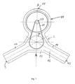
- a tub 1 ( FIG. 2 and 3 ) of a washing machine has a laundry drum (not shown) rotating in it, which has a horizontal ( Fig.2 ) or inclined ( Fig. 3 ) lying wave 2 is flying in the tub 1 is stored. It is possible to realize inclinations of, for example, 10 ° or 15 ° with respect to the horizontal; It is understood that according to the invention, larger inclinations can be selected.
- the shaft 2 of the laundry drum is mounted in a support member 3. This has a bearing bush 4, the bearing 5 and 6, for example, ball bearings, receives, in which the shaft 2 is mounted.
- a ring seal 7 is provided, which surrounds the shaft 2 in the region of the rear wall 8 of the tub 1.
- the support member 3 is fixedly connected to the rear wall 8, for example via screw.
- the support member 3 has star-shaped from the center of the rear wall 8 outgoing arms 9, 10 and 11 ( FIG. 1 ) on.
- the arms 9 to 11 each have a U-shaped profile and, in addition to a resting on the rear wall 8 wall 12 perpendicular to the rear wall 8 repellent side walls 13 and 14.
- the arm 11 has a cup-shaped widening 17 for receiving a motor 16.
- the support member 3 In the middle of the widening 17, the support member 3 has a facing away from the rear wall 8 flange 18 for receiving the motor shaft 19, which is mounted in the flange 18 via bearings 20 and 21.
- stator 22 At the flange 18 stator 22 are fixed, the excitation windings 23 carry.
- the stator 22 are on the inner wall of a bell-shaped, the rotor of the motor 16 forming flange 24 fixed magnetic poles 25 in the radial direction opposite.
- the stator packs may also be disposed on the wall of the support member 3 extending along the back wall 8 and the magnetic poles 25 may be mounted on the bottom of the flange 24 substantially coplanar with this wall.
- the flange 24 is mounted on a shaft extension 26 forming the extension of the motor shaft 19.
- the shaft journal 26 also serves to receive a pulley 27 for a V-ribbed belt 28.
- the flange 24 at least partially covers upwards and laterally, penetration of dirt particles in the area between the stator 22 and the poles 25 is effectively prevented.
- the formed by the wall 12 and the side walls 13 to 15 U-shaped profile gives the arms 9 to 11 high stability.
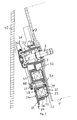
- FIG. 3 Drive device shown a motor 32 arranged on the rear wall 8 of the tub 1 facing side of a support member 33.
- the support member 33 is also star-shaped as the support member 3, however, has in the region of its a cup-shaped broadening 34a having support arm 34 has a different structure than the support member 3.
- the support arm 34 consists of a plate and a perpendicular standing on this, substantially circular
- the motor 32 is constructed in the same manner as the motor 16, as indicated by the use of the same reference numerals. Also in this case, the stator and the poles can be arranged in the axial direction.
- the motor 32 drives a V-ribbed belt 41 via a motor shaft 37, which is mounted in a bearing 38 forming its bearing sleeve flange 38 of the support arm 34, a V-ribbed belt 41 in the same manner as the motor 16, the V-ribbed belt 28th
- a drive device is provided with an indirect drive for the shaft 2, so that this compared to a directly driving the shaft 2 motor, as he from the DE 195 47 745 A1 It is known that only a lower torque needs to be applied.
- the rotational speed of the motor shaft 19 and 37 in the ratio of, for example, 3: 1 or 4: 1 reduced. In this way, a motor can be built with less material than is the case with a direct drive.
- External rotor motors shown can also be used internal rotor motors, which have the same size, ie the arrangement of the air gap at the same place a smaller rotor and thus a lower Torque can muster as the external rotor motor. Because the motor 16 or 32 is arranged in the area behind the rear wall 8 of the tub 1 due to its compact construction, the space below the tub 1 for other facilities of the washing machine is available.
- motor 16, 32 can be both an asynchronous motor, a DC motor or a reluctance motor provide.
- the asynchronous motor is controlled by a frequency converter
- the DC motor is a brushless, controlled by a power converter, electronically commutated motor. Due to the converter drive, the motors 16, 32 can be controlled in a positionally exact manner and decelerated to the exact position.
- the spatial resolution of the Abbremsposition of the motor 16, 32 of ⁇ 3 ° results in a reduction ratio of 3: 1 a drum position resolution of ⁇ 1 °.
- the spatial resolution is still increased by the reduction gear.
- a precise spatial resolution can be achieved in particular when using a gear transmission, in particular with helical gears, as well as when using a toothed belt instead of a simple V-belt or V-ribbed belt.
- the V-ribbed belt 28, 41 or a corresponding V-belt or toothed belt on the outer wall 31 of the flange 30 has a larger wrap angle and can thus be made narrower than in a conventional drive.
- the engine 16 is as in FIG. 2 shown, arranged on a separate support member 3.
- FIG. 3 A particularly advantageous construction of the washing machine results when these, as in Fig. 3 shown. one with the filling upwardly inclined relative to the horizontal washing drum and an equally inclined shaft 2, so that the rear wall 8 is also inclined relative to the vertical and the motor 16, 32 below the shaft 2 in the region between the rear wall 8 and the rear wall 42 of the washing machine is arranged. This results in an extremely space-saving storage of the motor 16, 32nd
- a drive device for one of the feedable washing machine with a within a standing with the rear wall 8 of the tub 1 in a fixed connection bearing sleeve 4 via a substantially horizontally disposed shaft 2 mounted laundry drum is arranged by a likewise behind the back 8 of the tub 1 motor 16 , 32 driven.
- the motor 16, 32 outside the center formed by the shaft 2 of the rear wall 8 but arranged behind this. It transmits its torque via a gear, which is formed for example by a disc 27 and a V-ribbed belt 28, 41, on the shaft second
Landscapes
- Engineering & Computer Science (AREA)
- Power Engineering (AREA)
- Textile Engineering (AREA)
- Main Body Construction Of Washing Machines And Laundry Dryers (AREA)
- Cleaning By Liquid Or Steam (AREA)
- Detail Structures Of Washing Machines And Dryers (AREA)
- Treatment Of Water By Ion Exchange (AREA)
- Crushing And Pulverization Processes (AREA)
Claims (12)
- Machine à laver à chargement frontal comprenant une cuve à lessive (1) et un tambour à linge qui est entraîné par un moteur (16, 32) situé derrière la paroi postérieure (8) de la cuve à lessive (1) et qui est monté en porte-à-faux par le biais d'un arbre (2) à l'intérieur d'un palier de support (4) en liaison fixe avec la paroi postérieure (8) de la cuve à lessive (1), le moteur (16, 32) étant situé derrière la paroi postérieure (8) à l'extérieur du centre de la paroi postérieure (8) formé par l'arbre (2) et le couple de rotation produit par le moteur (16, 32) étant transmis à l'arbre (2) par le biais d'une transmission, caractérisée en ce que le moteur (16, 32) est fixé sur un élément porteur (3, 33) fixé sur la paroi postérieure (8) et situé derrière celle-ci, l'élément porteur (3, 33) étant formé par des bras (9, 10, 11) qui s'étendent du centre de la paroi postérieure (8) vers l'extérieur et le moteur (16, 32) étant situé sur un de ces bras (9, 10, 11) qui présente un élargissement (17) essentiellement en forme de pot qui reçoit le moteur (16, 32).
- Machine à laver selon la revendication 1, caractérisée en ce que le moteur (16) est situé sur le côté de l'élément porteur (3) détourné de la paroi postérieure (8).
- Machine à laver selon la revendication 1, caractérisée en ce que le moteur (32) est situé sur l'élément porteur (3) dans la zone entre l'élément porteur (33) et la paroi postérieure (8) de la cuve à lessive (1).
- Machine à laver selon l'une des revendications 1 à 3, caractérisée en ce qu'un arbre de moteur (19, 37) est entraîné par le moteur (16, 32) et une courroie trapézoïdale, une courroie crantée ou une courroie trapézoïdale à nervures (28, 41) est entraînée par le biais de l'arbre ainsi que d'un disque (27) installé sur lui, la courroie trapézoïdale, la courroie crantée ou la courroie trapézoïdale à nervures (28, 41) entourant quant à elle un disque situé sur l'arbre (2) ou une bride (31) en forme de cloche située sur celui-ci et l'entraînant.
- Machine à laver selon l'une des revendications 1 à 3, caractérisée en ce que l'arbre (2) du tambour à linge est entraîné par le biais d'une transmission présentant des roues dentées, notamment des roues dentées à denture inclinée.
- Machine à laver selon l'une des revendications 1 à 5, caractérisée en ce que le moteur (16, 32) est exécuté en tant que moteur à induit extérieur.
- Machine à laver selon l'une des revendications 1 à 6, caractérisée en ce que l'élément porteur (3, 33) est pourvu d'une bride (18, 38) formant le palier de support de l'arbre de moteur (19, 37) qui porte les paquets de stator (22).
- Machine à laver selon l'une des revendications 1 à 7, caractérisée en ce que les paquets de stator (22) et les pôles magnétiques (25) de l'induit sont opposés les uns aux autres par rapport à l'arbre de moteur (19, 37) dans la direction axiale ou dans la direction radiale.
- Machine à laver selon l'une des revendications 1 à 8, caractérisée en ce que l'élément porteur (3) est pourvu d'une paroi latérale (14, 36) couvrant de manière essentiellement annulaire l'induit du moteur (16, 32).
- Machine à laver selon l'une des revendications 1 à 9, caractérisée en ce que l'induit du moteur (16, 32) est exécuté en tant que bride en forme de cloche (24, 35).
- Machine à laver selon l'une des revendications 1 à 10, caractérisée en ce que, avec un tambour à linge dont l'ouverture de remplissage est inclinée vers le haut, le moteur (16, 32) est situé au-dessous de l'arbre (2) dans la zone entre la paroi postérieure (8) et la paroi postérieure (42) de la machine à laver.
- Machine à laver selon l'une des revendications 1 à 11, caractérisée en ce que le moteur (16, 32) est un moteur à courant continu à commutation électronique, un moteur asynchrone commandé par le biais d'un convertisseur de fréquence ou un moteur à réluctance.
Priority Applications (1)
| Application Number | Priority Date | Filing Date | Title |
|---|---|---|---|
| SI200030485T SI1163388T1 (en) | 1999-03-12 | 2000-03-10 | Front-loading washing machine |
Applications Claiming Priority (3)
| Application Number | Priority Date | Filing Date | Title |
|---|---|---|---|
| DE19911139 | 1999-03-12 | ||
| DE19911139A DE19911139A1 (de) | 1999-03-12 | 1999-03-12 | Antriebsvorrichtung für eine von vorn beschickbare Waschmaschine |
| PCT/EP2000/002133 WO2000055414A1 (fr) | 1999-03-12 | 2000-03-10 | Dispositif d'entrainement pour machine a laver a chargement frontal |
Publications (3)
| Publication Number | Publication Date |
|---|---|
| EP1163388A1 EP1163388A1 (fr) | 2001-12-19 |
| EP1163388B1 EP1163388B1 (fr) | 2004-10-13 |
| EP1163388B2 true EP1163388B2 (fr) | 2009-08-05 |
Family
ID=7900797
Family Applications (1)
| Application Number | Title | Priority Date | Filing Date |
|---|---|---|---|
| EP00912592A Expired - Lifetime EP1163388B2 (fr) | 1999-03-12 | 2000-03-10 | Machine a laver a chargement frontal |
Country Status (7)
| Country | Link |
|---|---|
| US (1) | US6499323B2 (fr) |
| EP (1) | EP1163388B2 (fr) |
| AT (1) | ATE279563T1 (fr) |
| DE (2) | DE19911139A1 (fr) |
| ES (1) | ES2230080T3 (fr) |
| TR (1) | TR200102429T2 (fr) |
| WO (1) | WO2000055414A1 (fr) |
Families Citing this family (15)
| Publication number | Priority date | Publication date | Assignee | Title |
|---|---|---|---|---|
| DE10062364A1 (de) | 2000-12-14 | 2002-06-20 | Bsh Bosch Siemens Hausgeraete | Antriebsvorrichtung für ein Haushaltsgerät und Verfahren zur Montage eines Elektromotors |
| DE10064549A1 (de) * | 2000-12-22 | 2002-06-27 | Bsh Bosch Siemens Hausgeraete | Trommelwaschmaschine mit verbesserter Wasch- oder Spülflüssigkeitszufuhr in die Innentrommel |
| US8256246B2 (en) * | 2003-10-29 | 2012-09-04 | Miele & Cie. Kg. | Aggregate for a washing machine with a plastic sudsing container |
| PL2241666T3 (pl) | 2003-10-29 | 2012-03-30 | Miele & Cie | Sposób wytwarzania agregatu piorącego z pojemnikiem na detergenty wykonanym z tworzywa sztucznego |
| KR20050089355A (ko) * | 2004-03-04 | 2005-09-08 | 엘지전자 주식회사 | 대용량 드럼세탁기용 비엘디시 모터 |
| DE102004049549A1 (de) * | 2004-03-24 | 2005-10-13 | Diehl Ako Stiftung & Co. Kg | Motor als Direktantrieb und Verfahren zur Montage des Motors |
| US7342334B2 (en) * | 2004-10-29 | 2008-03-11 | Emerson Electric Co. | Insulated stator with wire routing element |
| US7685665B2 (en) * | 2006-09-13 | 2010-03-30 | General Electric Company | Washing machine having self-centering drive assembly |
| ITMI20070304U1 (it) | 2007-09-11 | 2009-03-12 | Askoll Holding Srl | Supporto per il fissaggio di un motore elettrico ad una vasca di una lavatrice o simile elettrodomestico |
| DE102010062916A1 (de) | 2010-12-13 | 2012-06-14 | BSH Bosch und Siemens Hausgeräte GmbH | Hausgerät zur Pflege von Wäschestücken |
| DE102012024703A1 (de) * | 2012-12-18 | 2014-06-18 | Robert Bosch Gmbh | Lagerhülse mit Manschette |
| JP2020022277A (ja) * | 2018-08-01 | 2020-02-06 | 日本電産テクノモータ株式会社 | モータ |
| US11124912B2 (en) | 2018-08-09 | 2021-09-21 | Haier Us Appliance Solutions, Inc. | Planetary helical gear train for a transmission assembly of a washing machine appliance |
| KR102737008B1 (ko) * | 2020-09-04 | 2024-12-02 | 엘지전자 주식회사 | 의류처리장치 |
| EP4394106A1 (fr) | 2022-12-28 | 2024-07-03 | Arçelik Anonim Sirketi | Machine à laver comprenant une cuve |
Citations (6)
| Publication number | Priority date | Publication date | Assignee | Title |
|---|---|---|---|---|
| US2296260A (en) † | 1938-08-26 | 1942-09-22 | Westinghouse Electric & Mfg Co | Apparatus for washing fabrics or the like |
| US2895320A (en) † | 1955-06-15 | 1959-07-21 | Gen Motors Corp | Washer |
| US3111017A (en) † | 1956-11-06 | 1963-11-19 | Hoover Co | Timer control for automatic washing and drying machines |
| DE1933117U (de) † | 1965-08-27 | 1966-02-24 | Beumer K G Geb | Waschmaschine od. dgl. |
| DE3132211C2 (fr) † | 1981-08-14 | 1987-12-10 | Licentia Patent-Verwaltungs-Gmbh, 6000 Frankfurt, De | |
| DE19547745A1 (de) † | 1995-12-20 | 1997-06-26 | Bosch Siemens Hausgeraete | Antriebsvorrichtung für eine von vorn beschickbare Waschmaschine |
Family Cites Families (6)
| Publication number | Priority date | Publication date | Assignee | Title |
|---|---|---|---|---|
| US2625031A (en) * | 1948-07-02 | 1953-01-13 | Standard Telephones Cables Ltd | Washing machine provided with resilient collapsible inlet |
| US2687861A (en) * | 1951-07-03 | 1954-08-31 | Itt | Washing machine support |
| LU37211A1 (fr) * | 1958-05-23 | |||
| DE1933827B2 (de) * | 1969-07-03 | 1972-10-12 | Danfoss A/S, Nordborg (Dänemark) | Antriebsvorrichtung fuer eine waschmaschine |
| US4914331A (en) * | 1988-08-02 | 1990-04-03 | Emerson Electric Co. | Minimum height motor assembly using aluminum endshields |
| DE3927426B4 (de) * | 1989-08-19 | 2006-02-23 | Ebm-Papst Mulfingen Gmbh & Co. Kg | Antriebseinheit für eine Wäsche-Behandlungsmaschine |
-
1999
- 1999-03-12 DE DE19911139A patent/DE19911139A1/de not_active Withdrawn
-
2000
- 2000-03-10 AT AT00912592T patent/ATE279563T1/de not_active IP Right Cessation
- 2000-03-10 TR TR2001/02429T patent/TR200102429T2/xx unknown
- 2000-03-10 WO PCT/EP2000/002133 patent/WO2000055414A1/fr not_active Ceased
- 2000-03-10 DE DE2000508233 patent/DE50008233D1/de not_active Expired - Lifetime
- 2000-03-10 ES ES00912592T patent/ES2230080T3/es not_active Expired - Lifetime
- 2000-03-10 EP EP00912592A patent/EP1163388B2/fr not_active Expired - Lifetime
-
2001
- 2001-09-12 US US09/951,238 patent/US6499323B2/en not_active Expired - Lifetime
Patent Citations (6)
| Publication number | Priority date | Publication date | Assignee | Title |
|---|---|---|---|---|
| US2296260A (en) † | 1938-08-26 | 1942-09-22 | Westinghouse Electric & Mfg Co | Apparatus for washing fabrics or the like |
| US2895320A (en) † | 1955-06-15 | 1959-07-21 | Gen Motors Corp | Washer |
| US3111017A (en) † | 1956-11-06 | 1963-11-19 | Hoover Co | Timer control for automatic washing and drying machines |
| DE1933117U (de) † | 1965-08-27 | 1966-02-24 | Beumer K G Geb | Waschmaschine od. dgl. |
| DE3132211C2 (fr) † | 1981-08-14 | 1987-12-10 | Licentia Patent-Verwaltungs-Gmbh, 6000 Frankfurt, De | |
| DE19547745A1 (de) † | 1995-12-20 | 1997-06-26 | Bosch Siemens Hausgeraete | Antriebsvorrichtung für eine von vorn beschickbare Waschmaschine |
Also Published As
| Publication number | Publication date |
|---|---|
| TR200102429T2 (tr) | 2002-01-21 |
| US6499323B2 (en) | 2002-12-31 |
| DE19911139A1 (de) | 2000-09-14 |
| ES2230080T3 (es) | 2005-05-01 |
| US20020069679A1 (en) | 2002-06-13 |
| ATE279563T1 (de) | 2004-10-15 |
| WO2000055414A1 (fr) | 2000-09-21 |
| EP1163388A1 (fr) | 2001-12-19 |
| EP1163388B1 (fr) | 2004-10-13 |
| DE50008233D1 (de) | 2004-11-18 |
Similar Documents
| Publication | Publication Date | Title |
|---|---|---|
| EP1163388B2 (fr) | Machine a laver a chargement frontal | |
| DE112008002101B4 (de) | Gurtstrafferantrieb für den Sicherheitsgurt eines Fahrzeugs mit einem Topflager für die Rotorwelle eines Elektromotors | |
| DE69909133T2 (de) | Aufzugsantrieb mit gegenläufigen rotoren | |
| DE69635136T2 (de) | Vorrichtung zum direkten verbinden eines verbrennungsmotors mit einer angetriebenen maschine | |
| EP1141466A1 (fr) | Dispositif d'entrainement pour machine a laver le linge chargeable par l'avant | |
| DE102007031508A1 (de) | Motor und Wischervorrichtung, die den Motor enthält | |
| EP1627727B1 (fr) | Presse rotative pour comprimés | |
| DE3927426A1 (de) | Antriebseinheit fuer eine waesche-behandlungsmaschine | |
| EP0657575B1 (fr) | Machine à laver | |
| DE19634629B4 (de) | Getriebelose Antriebsvorrichtung für Aufzüge | |
| DE19833794A1 (de) | Handgeführtes Elektrowerkzeug, insbesondere Stichsäge | |
| DE1463076A1 (de) | Motorverdichter,insbesondere fuer Kleinkaeltemaschinen | |
| DE2633415A1 (de) | Kuehlmittelkompressor | |
| EP0444540B1 (fr) | Malaxeur | |
| EP0491424B2 (fr) | Appareil ménager électrique | |
| DE60033501T2 (de) | Rotierender exzenterantrieb. | |
| EP1048603B1 (fr) | Disposition inclinée de la machinerie d'un ascenseur à câbles | |
| DE60200206T2 (de) | Verbesserte Vorrichtung zur Übertragung von Bewegung zwischen dem Läufer eines Synchronmotors mit Permanentmagneten und einer Arbeitspartie | |
| DE19905390C1 (de) | Aufzugsantrieb mit elektrischem Antriebsmotor | |
| DE69600715T2 (de) | Anlasserzusammenbau für Verbrennungsmotor | |
| DE3931736C2 (fr) | ||
| DE19721974C2 (de) | Elektrische Küchenmaschine mit Riemenantrieb | |
| EP1550630B1 (fr) | Moteur électrique pour ascenseur | |
| DE19917582A1 (de) | Antriebsvorrichtung für eine Waschmaschine | |
| EP0575726A1 (fr) | Entraînement de mélangeur |
Legal Events
| Date | Code | Title | Description |
|---|---|---|---|
| PUAI | Public reference made under article 153(3) epc to a published international application that has entered the european phase |
Free format text: ORIGINAL CODE: 0009012 |
|
| 17P | Request for examination filed |
Effective date: 20011012 |
|
| AK | Designated contracting states |
Kind code of ref document: A1 Designated state(s): AT BE CH CY DE DK ES FI FR GB GR IE IT LI LU MC NL PT SE |
|
| AX | Request for extension of the european patent |
Free format text: SI PAYMENT 20011012 |
|
| 17Q | First examination report despatched |
Effective date: 20030711 |
|
| RAP1 | Party data changed (applicant data changed or rights of an application transferred) |
Owner name: BSH BOSCH UND SIEMENS HAUSGERAETE GMBH |
|
| RTI1 | Title (correction) |
Free format text: FRONT-LOADING WASHING MACHINE |
|
| GRAP | Despatch of communication of intention to grant a patent |
Free format text: ORIGINAL CODE: EPIDOSNIGR1 |
|
| GRAS | Grant fee paid |
Free format text: ORIGINAL CODE: EPIDOSNIGR3 |
|
| GRAA | (expected) grant |
Free format text: ORIGINAL CODE: 0009210 |
|
| AK | Designated contracting states |
Kind code of ref document: B1 Designated state(s): AT BE CH CY DE DK ES FI FR GB GR IE IT LI LU MC NL PT SE |
|
| AX | Request for extension of the european patent |
Extension state: SI |
|
| PG25 | Lapsed in a contracting state [announced via postgrant information from national office to epo] |
Ref country code: NL Free format text: LAPSE BECAUSE OF FAILURE TO SUBMIT A TRANSLATION OF THE DESCRIPTION OR TO PAY THE FEE WITHIN THE PRESCRIBED TIME-LIMIT Effective date: 20041013 Ref country code: FI Free format text: LAPSE BECAUSE OF FAILURE TO SUBMIT A TRANSLATION OF THE DESCRIPTION OR TO PAY THE FEE WITHIN THE PRESCRIBED TIME-LIMIT Effective date: 20041013 Ref country code: IE Free format text: LAPSE BECAUSE OF FAILURE TO SUBMIT A TRANSLATION OF THE DESCRIPTION OR TO PAY THE FEE WITHIN THE PRESCRIBED TIME-LIMIT Effective date: 20041013 |
|
| REG | Reference to a national code |
Ref country code: GB Ref legal event code: FG4D Free format text: NOT ENGLISH |
|
| REG | Reference to a national code |
Ref country code: CH Ref legal event code: NV Representative=s name: SIEMENS SCHWEIZ AG Ref country code: CH Ref legal event code: EP |
|
| GBT | Gb: translation of ep patent filed (gb section 77(6)(a)/1977) |
Effective date: 20041013 |
|
| REG | Reference to a national code |
Ref country code: IE Ref legal event code: FG4D Free format text: GERMAN |
|
| REF | Corresponds to: |
Ref document number: 50008233 Country of ref document: DE Date of ref document: 20041118 Kind code of ref document: P |
|
| PG25 | Lapsed in a contracting state [announced via postgrant information from national office to epo] |
Ref country code: SE Free format text: LAPSE BECAUSE OF FAILURE TO SUBMIT A TRANSLATION OF THE DESCRIPTION OR TO PAY THE FEE WITHIN THE PRESCRIBED TIME-LIMIT Effective date: 20050113 Ref country code: DK Free format text: LAPSE BECAUSE OF FAILURE TO SUBMIT A TRANSLATION OF THE DESCRIPTION OR TO PAY THE FEE WITHIN THE PRESCRIBED TIME-LIMIT Effective date: 20050113 Ref country code: GR Free format text: LAPSE BECAUSE OF FAILURE TO SUBMIT A TRANSLATION OF THE DESCRIPTION OR TO PAY THE FEE WITHIN THE PRESCRIBED TIME-LIMIT Effective date: 20050113 |
|
| PG25 | Lapsed in a contracting state [announced via postgrant information from national office to epo] |
Ref country code: LU Free format text: LAPSE BECAUSE OF NON-PAYMENT OF DUE FEES Effective date: 20050310 Ref country code: CY Free format text: LAPSE BECAUSE OF FAILURE TO SUBMIT A TRANSLATION OF THE DESCRIPTION OR TO PAY THE FEE WITHIN THE PRESCRIBED TIME-LIMIT Effective date: 20050310 |
|
| PG25 | Lapsed in a contracting state [announced via postgrant information from national office to epo] |
Ref country code: MC Free format text: LAPSE BECAUSE OF NON-PAYMENT OF DUE FEES Effective date: 20050331 Ref country code: BE Free format text: LAPSE BECAUSE OF NON-PAYMENT OF DUE FEES Effective date: 20050331 |
|
| NLV1 | Nl: lapsed or annulled due to failure to fulfill the requirements of art. 29p and 29m of the patents act | ||
| REG | Reference to a national code |
Ref country code: ES Ref legal event code: FG2A Ref document number: 2230080 Country of ref document: ES Kind code of ref document: T3 |
|
| REG | Reference to a national code |
Ref country code: IE Ref legal event code: FD4D |
|
| ET | Fr: translation filed | ||
| PLBI | Opposition filed |
Free format text: ORIGINAL CODE: 0009260 |
|
| PLAX | Notice of opposition and request to file observation + time limit sent |
Free format text: ORIGINAL CODE: EPIDOSNOBS2 |
|
| 26 | Opposition filed |
Opponent name: MIELE & CIE. KGSCHUTZRECHTE/VERTRAEGE Effective date: 20050713 |
|
| BERE | Be: lapsed |
Owner name: BSH BOSCH UND SIEMENS HAUSGERATE G.M.B.H. Effective date: 20050331 |
|
| PLAF | Information modified related to communication of a notice of opposition and request to file observations + time limit |
Free format text: ORIGINAL CODE: EPIDOSCOBS2 |
|
| PLBB | Reply of patent proprietor to notice(s) of opposition received |
Free format text: ORIGINAL CODE: EPIDOSNOBS3 |
|
| BERE | Be: lapsed |
Owner name: BOSCH UND SIEMENS HAUSGERATE G.M.B.H. *BSH Effective date: 20050331 |
|
| PG25 | Lapsed in a contracting state [announced via postgrant information from national office to epo] |
Ref country code: PT Free format text: LAPSE BECAUSE OF NON-PAYMENT OF DUE FEES Effective date: 20050313 |
|
| REG | Reference to a national code |
Ref country code: CH Ref legal event code: PCAR Free format text: SIEMENS SCHWEIZ AG;INTELLECTUAL PROPERTY FREILAGERSTRASSE 40;8047 ZUERICH (CH) |
|
| PGFP | Annual fee paid to national office [announced via postgrant information from national office to epo] |
Ref country code: ES Payment date: 20090325 Year of fee payment: 10 Ref country code: AT Payment date: 20090323 Year of fee payment: 10 |
|
| PGFP | Annual fee paid to national office [announced via postgrant information from national office to epo] |
Ref country code: CH Payment date: 20090325 Year of fee payment: 10 |
|
| PUAH | Patent maintained in amended form |
Free format text: ORIGINAL CODE: 0009272 |
|
| STAA | Information on the status of an ep patent application or granted ep patent |
Free format text: STATUS: PATENT MAINTAINED AS AMENDED |
|
| 27A | Patent maintained in amended form |
Effective date: 20090805 |
|
| AK | Designated contracting states |
Kind code of ref document: B2 Designated state(s): AT BE CH CY DE DK ES FI FR GB GR IE IT LI LU MC NL PT SE |
|
| AX | Request for extension of the european patent |
Extension state: SI |
|
| REG | Reference to a national code |
Ref country code: CH Ref legal event code: AEN Free format text: AUFRECHTERHALTUNG DES PATENTES IN GEAENDERTER FORM |
|
| PG25 | Lapsed in a contracting state [announced via postgrant information from national office to epo] |
Ref country code: ES Free format text: LAPSE BECAUSE OF FAILURE TO SUBMIT A TRANSLATION OF THE DESCRIPTION OR TO PAY THE FEE WITHIN THE PRESCRIBED TIME-LIMIT Effective date: 20091116 |
|
| REG | Reference to a national code |
Ref country code: CH Ref legal event code: PL |
|
| PG25 | Lapsed in a contracting state [announced via postgrant information from national office to epo] |
Ref country code: AT Free format text: LAPSE BECAUSE OF NON-PAYMENT OF DUE FEES Effective date: 20100310 |
|
| REG | Reference to a national code |
Ref country code: SI Ref legal event code: KO00 Effective date: 20101015 |
|
| PG25 | Lapsed in a contracting state [announced via postgrant information from national office to epo] |
Ref country code: CH Free format text: LAPSE BECAUSE OF NON-PAYMENT OF DUE FEES Effective date: 20100331 Ref country code: LI Free format text: LAPSE BECAUSE OF NON-PAYMENT OF DUE FEES Effective date: 20100331 |
|
| PGFP | Annual fee paid to national office [announced via postgrant information from national office to epo] |
Ref country code: FR Payment date: 20120403 Year of fee payment: 13 |
|
| REG | Reference to a national code |
Ref country code: FR Ref legal event code: ST Effective date: 20131129 |
|
| PG25 | Lapsed in a contracting state [announced via postgrant information from national office to epo] |
Ref country code: FR Free format text: LAPSE BECAUSE OF NON-PAYMENT OF DUE FEES Effective date: 20130402 |
|
| PGFP | Annual fee paid to national office [announced via postgrant information from national office to epo] |
Ref country code: DE Payment date: 20140331 Year of fee payment: 15 |
|
| PGFP | Annual fee paid to national office [announced via postgrant information from national office to epo] |
Ref country code: IT Payment date: 20140327 Year of fee payment: 15 |
|
| PGFP | Annual fee paid to national office [announced via postgrant information from national office to epo] |
Ref country code: GB Payment date: 20140324 Year of fee payment: 15 |
|
| REG | Reference to a national code |
Ref country code: DE Ref legal event code: R119 Ref document number: 50008233 Country of ref document: DE |
|
| GBPC | Gb: european patent ceased through non-payment of renewal fee |
Effective date: 20150310 |
|
| PG25 | Lapsed in a contracting state [announced via postgrant information from national office to epo] |
Ref country code: IT Free format text: LAPSE BECAUSE OF NON-PAYMENT OF DUE FEES Effective date: 20150310 |
|
| PG25 | Lapsed in a contracting state [announced via postgrant information from national office to epo] |
Ref country code: GB Free format text: LAPSE BECAUSE OF NON-PAYMENT OF DUE FEES Effective date: 20150310 Ref country code: DE Free format text: LAPSE BECAUSE OF NON-PAYMENT OF DUE FEES Effective date: 20151001 |