EP1164247A2 - Fenêtre ou porte avec un profilé de recouvrement fixé sur la face extérieure - Google Patents
Fenêtre ou porte avec un profilé de recouvrement fixé sur la face extérieure Download PDFInfo
- Publication number
- EP1164247A2 EP1164247A2 EP01114195A EP01114195A EP1164247A2 EP 1164247 A2 EP1164247 A2 EP 1164247A2 EP 01114195 A EP01114195 A EP 01114195A EP 01114195 A EP01114195 A EP 01114195A EP 1164247 A2 EP1164247 A2 EP 1164247A2
- Authority
- EP
- European Patent Office
- Prior art keywords
- profile
- window
- cladding profile
- cladding
- door according
- Prior art date
- Legal status (The legal status is an assumption and is not a legal conclusion. Google has not performed a legal analysis and makes no representation as to the accuracy of the status listed.)
- Withdrawn
Links
- 238000005253 cladding Methods 0.000 title claims abstract description 64
- 239000011521 glass Substances 0.000 claims abstract description 19
- 239000013013 elastic material Substances 0.000 claims abstract description 10
- 238000007789 sealing Methods 0.000 claims description 4
- 229910052782 aluminium Inorganic materials 0.000 description 16
- XAGFODPZIPBFFR-UHFFFAOYSA-N aluminium Chemical compound [Al] XAGFODPZIPBFFR-UHFFFAOYSA-N 0.000 description 14
- 238000010276 construction Methods 0.000 description 6
- 230000006978 adaptation Effects 0.000 description 2
- 239000000463 material Substances 0.000 description 2
- 239000002023 wood Substances 0.000 description 2
- 229920002943 EPDM rubber Polymers 0.000 description 1
- 238000000576 coating method Methods 0.000 description 1
- 229920001821 foam rubber Polymers 0.000 description 1
- 238000003780 insertion Methods 0.000 description 1
- 230000037431 insertion Effects 0.000 description 1
- 238000004519 manufacturing process Methods 0.000 description 1
- 125000006850 spacer group Chemical group 0.000 description 1
- 238000009423 ventilation Methods 0.000 description 1
Images


Classifications
-
- E—FIXED CONSTRUCTIONS
- E06—DOORS, WINDOWS, SHUTTERS, OR ROLLER BLINDS IN GENERAL; LADDERS
- E06B—FIXED OR MOVABLE CLOSURES FOR OPENINGS IN BUILDINGS, VEHICLES, FENCES OR LIKE ENCLOSURES IN GENERAL, e.g. DOORS, WINDOWS, BLINDS, GATES
- E06B3/00—Window sashes, door leaves, or like elements for closing wall or like openings; Layout of fixed or moving closures, e.g. windows in wall or like openings; Features of rigidly-mounted outer frames relating to the mounting of wing frames
- E06B3/30—Coverings, e.g. protecting against weather, for decorative purposes
- E06B3/301—Coverings, e.g. protecting against weather, for decorative purposes consisting of prefabricated profiled members or glass
- E06B3/302—Covering wooden frames with metal or plastic profiled members
-
- E—FIXED CONSTRUCTIONS
- E06—DOORS, WINDOWS, SHUTTERS, OR ROLLER BLINDS IN GENERAL; LADDERS
- E06B—FIXED OR MOVABLE CLOSURES FOR OPENINGS IN BUILDINGS, VEHICLES, FENCES OR LIKE ENCLOSURES IN GENERAL, e.g. DOORS, WINDOWS, BLINDS, GATES
- E06B3/00—Window sashes, door leaves, or like elements for closing wall or like openings; Layout of fixed or moving closures, e.g. windows in wall or like openings; Features of rigidly-mounted outer frames relating to the mounting of wing frames
- E06B3/54—Fixing of glass panes or like plates
- E06B3/58—Fixing of glass panes or like plates by means of borders, cleats, or the like
- E06B3/62—Fixing of glass panes or like plates by means of borders, cleats, or the like of rubber-like elastic cleats
Definitions
- the invention relates to a window or a door with a placed on the outer surface, in essentially two cladding profile having an obtuse angle enclosing legs.
- Such constructions have become known in a wide variety of designs.
- a wood-aluminum window is placed on the Outside surface of the wooden profiles placed aluminum profiles known, the aluminum profiles Wooden profiles on three sides with tight play form-fitting comprehensive shells and in the covering area longitudinal ventilation grooves are milled into the wooden profiles. It is an exact fit in this way between the wooden frame and aluminum profile required, with a snap on both edge areas of the aluminum profile is required to hold securely between the aluminum profile and the wooden profile to ensure.
- the present invention has for its object a window or a door of the aforementioned Art to create, with a simple assembly of the cladding profile on a casement is to be made possible without holding or latching elements having to be defined in advance.
- this is achieved in that the cladding profile on the edge region of one leg with a bent retaining lug for gripping around an undercut area of a casement the window or door is provided and in the area of the other leg support elements are provided for spacing relative to the casement, and that to secure the position of the Cladding profile on the casement between the edge area of one leg in the area bent retaining lug and a glass pane inserted into the casement at least one strips made partly of elastic material is used.
- An advantageous embodiment is that the retaining nose of the cladding profile approximately one U-cross-section is bent. It can effectively be a kind of hanging the cladding profile done on the casement so that just after inserting the strip of elastic material optimal protection against removal of the cladding profile is created.
- the U-shaped retaining lug has a flat cross section Has conclusion, which in the use position of the cladding profile at least approximately in one is parallel to the plane of the window or door. It is therefore a clear one Alignment of the free edge area of this retaining lug in relation to the glass pane used, so that an optimal load distribution over the inserted strips of elastic material is possible.
- the other leg of the cladding profile webs on the wing frame side or grooves for positively attaching support elements are provided.
- the support elements on their trim profile side boundary Bars and / or grooves for positive engagement on the cladding profile and on the have a support web on the edge of the sash frame.
- the support elements Made separately from the cladding profiles and can be made according to need and size be put together. It is therefore also possible to use the space between the outside Completion of the cladding profile and the sash to make any size. So there are also greater possibilities of variation with regard to the height or width of the cladding profile Given that the profile shape is much easier due to the separate production of the support elements can be designed.
- the cladding profile continuously along its length with a profile-like Support element is provided. This ensures a special strength in the support, however, an appropriate amount of material is required. It is therefore also conceivable that the Cladding profile seen along its length with several short sections profile-like Support elements is provided. With adequate rigidity of the cladding profile, it is sufficient also, short sections of support elements with a corresponding distance from each other in the Insert cladding profile.
- cladding profile and the support element (s) connect in one piece.
- Such a variant is certainly an advantage if a large number of constant cladding profiles with the same size and shape Casement should be used.
- the cladding profile solely by using a Strips of elastic material attached and secured in place.
- a Strips of elastic material attached and secured in place.
- no additional part has to be used here, but in itself required construction parts can be used.
- This strip of elastic material thus fulfills several purposes at the same time, namely, on the one hand, the sealing and supporting of the used Glass pane and on the other hand the fixation of the applied cladding profiles.
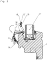
- a window or a door essentially consists of a casement 1 and a floor frame 2.
- the sash 1 has a groove 3 open on one side for receiving the Glass pane 4, a spacer for supporting and centering the glass pane 4 in the groove 3 5 is available with appropriate holding and centering elements. It is with a sash but also a construction can be used in which the glass pane 4 is inserted from the side can be, so that then the section 6 provided here on one side as retrofittable Glass holding bar is running.
- the cladding profile 7 is essentially two in the embodiment according to the invention obtuse angles forming legs 10 and 11 are formed. At the edge of one Leg 10 is formed a bent retaining lug 12, which for gripping around an undercut Area 13 of the sash 1 is used. In the area of the other leg 11 are Support elements 14 are provided, which are used for spacing relative to the casement 1.
- This strip 15 also forms the one inserted between the sash 1 and the glass pane 4 Sealing profile.
- This strip 15 can, for example, consist of two sections 16 and 17 Materials are manufactured, the section 16, for example, made of EPDM and
- Section 17 is made of foam rubber.
- any type of elastic strip can be used here can be used, which of course is also ideal for holding and supporting the glass pane 4 suitable is.
- the retaining lug 12 of the cladding profile 7 is bent approximately to form a U cross section, so that an optimal hooking of this retaining lug 12 into the groove 18 of the undercut area 13 is possible is.
- the free edge web 19 of the retaining lug 12 thus engages directly in the groove 18, so that after the insertion of the strip 15 a positive and non-positive mounting of the cladding profile 7 on Casement 1 is guaranteed.
- the cross-sectionally U-shaped retaining lug 12 has a flat end 20, which is in the operating position of the cladding profile at least approximately in a parallel to the plane of the glass pane 4 of the Window or door aligned level.
- the other leg 11 of the cladding profile 7 has webs 21, 22 or corresponding on the sash frame side Grooves in order to create the possibility of positively attaching support elements 14.
- these support elements 14 have an edge limitation on their cladding profile side Ridges 23, 24, which form-fit in the corresponding area of the cladding profile 7 can intervene.
- On the sash border edge of the support elements 14 is a corresponding support web 25 is provided, which is loose on the outside 26 of the casement 1 lies on.
- an undercut can be made between the two webs 21 and 22 Groove 28 are formed, with a bent on a web 23 of the support member 14 Edge area 27 for a snap-fit connection between the cladding profile and the support element 14 is formed.
- the support element can thus be positively and non-positively connected to the Cladding profile 7 are connected, while still a very simple and quick assembly is made possible.
- the support elements can be of different widths or lengths, depending on the required Strength of the support and according to the desired distance between the cladding profile 7 and the outer boundary 26 of the casement 1. It is thus a simple Adaptation to various structural designs possible with a window or a door.
- the cladding profile is usually made of aluminum, but of course also cladding profiles plastic can be used in the same way. It is also conceivable to have various To provide coatings and color schemes of the cladding profile, thereby additional Get variation and customization options.
Landscapes
- Engineering & Computer Science (AREA)
- Civil Engineering (AREA)
- Structural Engineering (AREA)
- Securing Of Glass Panes Or The Like (AREA)
Applications Claiming Priority (2)
| Application Number | Priority Date | Filing Date | Title |
|---|---|---|---|
| DE10029390 | 2000-06-15 | ||
| DE2000129390 DE10029390A1 (de) | 2000-06-15 | 2000-06-15 | Fenster oder Tür mit einem auf der Aussenfläche aufgesetzten Verkleidungsprofil |
Publications (2)
| Publication Number | Publication Date |
|---|---|
| EP1164247A2 true EP1164247A2 (fr) | 2001-12-19 |
| EP1164247A3 EP1164247A3 (fr) | 2002-10-23 |
Family
ID=7645761
Family Applications (1)
| Application Number | Title | Priority Date | Filing Date |
|---|---|---|---|
| EP01114195A Withdrawn EP1164247A3 (fr) | 2000-06-15 | 2001-06-12 | Fenêtre ou porte avec un profilé de recouvrement fixé sur la face extérieure |
Country Status (2)
| Country | Link |
|---|---|
| EP (1) | EP1164247A3 (fr) |
| DE (1) | DE10029390A1 (fr) |
Cited By (1)
| Publication number | Priority date | Publication date | Assignee | Title |
|---|---|---|---|---|
| GB2476264A (en) * | 2009-12-17 | 2011-06-22 | Susan Mary Boardman | Two part frame assembly with insulated joint |
Families Citing this family (2)
| Publication number | Priority date | Publication date | Assignee | Title |
|---|---|---|---|---|
| DE10217532A1 (de) * | 2002-04-17 | 2003-11-13 | Roto Frank Ag | Dachfenster mit geklipster Abdeckung |
| DE10322865A1 (de) * | 2003-04-23 | 2004-11-25 | Alco-Systeme Gmbh | Verfahren zur Herstellung von Rahmen für Fenster und/oder Türen |
Citations (3)
| Publication number | Priority date | Publication date | Assignee | Title |
|---|---|---|---|---|
| DE3844195A1 (de) | 1988-12-29 | 1990-07-05 | Gutmann Hermann Werke Gmbh | Fenster oder tuer in holz-alu-bauweise |
| EP0666400A1 (fr) | 1994-02-02 | 1995-08-09 | Hermann Gutmann Werke Gmbh | Fenêtre mixte bois-aluminium |
| EP0961002A1 (fr) | 1998-05-28 | 1999-12-01 | Hermann Gutmann Werke Gmbh | Système de rénovation pour fenêtres mixtes bois-aluminium |
Family Cites Families (4)
| Publication number | Priority date | Publication date | Assignee | Title |
|---|---|---|---|---|
| DE1697656U (de) * | 1955-02-03 | 1955-05-05 | Erich Grossmann | Stock- oder fluegelrahmen aus metallprofilen fuer fenster oder tueren. |
| DE3411098A1 (de) * | 1983-03-29 | 1984-10-04 | Hrachowina Bauelemente Produktions Gesellschaft mbH, Wien | Holzfenster oder -tuer |
| DE9400552U1 (de) * | 1994-01-14 | 1994-05-05 | Langner & Lehmann KG LANCO - Zargen, 84036 Landshut | Vorrichtung zum Schutz vor Bewitterung horizontaler Außenflächen von Holzfenstern |
| DE29710495U1 (de) * | 1997-06-18 | 1997-09-04 | Hoogovens Aluminium Profiltechnik Gmbh, 88267 Vogt | Halteprofil |
-
2000
- 2000-06-15 DE DE2000129390 patent/DE10029390A1/de not_active Ceased
-
2001
- 2001-06-12 EP EP01114195A patent/EP1164247A3/fr not_active Withdrawn
Patent Citations (3)
| Publication number | Priority date | Publication date | Assignee | Title |
|---|---|---|---|---|
| DE3844195A1 (de) | 1988-12-29 | 1990-07-05 | Gutmann Hermann Werke Gmbh | Fenster oder tuer in holz-alu-bauweise |
| EP0666400A1 (fr) | 1994-02-02 | 1995-08-09 | Hermann Gutmann Werke Gmbh | Fenêtre mixte bois-aluminium |
| EP0961002A1 (fr) | 1998-05-28 | 1999-12-01 | Hermann Gutmann Werke Gmbh | Système de rénovation pour fenêtres mixtes bois-aluminium |
Cited By (1)
| Publication number | Priority date | Publication date | Assignee | Title |
|---|---|---|---|---|
| GB2476264A (en) * | 2009-12-17 | 2011-06-22 | Susan Mary Boardman | Two part frame assembly with insulated joint |
Also Published As
| Publication number | Publication date |
|---|---|
| EP1164247A3 (fr) | 2002-10-23 |
| DE10029390A1 (de) | 2001-12-20 |
Similar Documents
| Publication | Publication Date | Title |
|---|---|---|
| EP1878847B1 (fr) | Structure de mur rideau | |
| DE202007016585U1 (de) | Profilschienensystem | |
| DE2059829A1 (de) | Struktursystem fuer den Zusammenbau von vorgefertigten Konstruktionen | |
| EP2666948A1 (fr) | Agencement de cadre pour un panneau de porte sectionnelle | |
| DE202014010902U1 (de) | Isolierelement für Fassaden- oder Lichtdachkonstruktionen | |
| EP1439278B1 (fr) | Joint automatique pour portes avec support adjustable | |
| EP1243738A2 (fr) | Fenêtre mixte bois-aluminium | |
| DE4210575A1 (de) | Unterkonstruktion für Glasdächer und Glasfassaden | |
| DE9407701U1 (de) | Bausatz zur Halterung einer aus Platten, insbesondere Glasplatten o.dgl. zusammensetzbaren Fassade oder Dacheindeckung | |
| EP1580344B1 (fr) | Joint droit pour la connexion angulaire de profilés creux, notamment pour fenêtres, portes et similaire | |
| DE2443098A1 (de) | Anordnung zur befestigung eines verkleidungsprofiles | |
| EP2460947B1 (fr) | Vitrage | |
| EP3293336B1 (fr) | Rail de retenue pour un balcon français ainsi que dispositif et système de retenue associés | |
| AT392814B (de) | Tragkonstruktion fuer ein aus scheibenartigen platten gebildetes dach bzw. wand | |
| DE3427899A1 (de) | Sonnenschutz fuer fenster oder tueren, insbesondere dachfenster | |
| DE10134396C1 (de) | Bausatz zum Einsetzen eines Wandelementes in eine Wandöffnung einer doppelschaligen Ständerwand | |
| DE4443232C1 (de) | Befestigungseinrichtung | |
| DE10029390A1 (de) | Fenster oder Tür mit einem auf der Aussenfläche aufgesetzten Verkleidungsprofil | |
| DE102004036265A1 (de) | Befestigungselement für mehrteilige Rahmen für Fenster oder dergl. | |
| EP0886028A2 (fr) | Profil de maintien | |
| DE9207858U1 (de) | Dachrinne | |
| DE2225653A1 (de) | Fensterzarge | |
| DE29705459U1 (de) | Vorrichtung zur Montage von Glaselementen an einem Tragrahmen zur Herstellung einer Fassadenverglasung | |
| DE3347184A1 (de) | Jalousie | |
| DE9015478U1 (de) | Befestigungsvorrichtung |
Legal Events
| Date | Code | Title | Description |
|---|---|---|---|
| PUAI | Public reference made under article 153(3) epc to a published international application that has entered the european phase |
Free format text: ORIGINAL CODE: 0009012 |
|
| AK | Designated contracting states |
Kind code of ref document: A2 Designated state(s): AT BE CH CY DE DK ES FI FR GB GR IE IT LI LU MC NL PT SE TR |
|
| AX | Request for extension of the european patent |
Free format text: AL;LT;LV;MK;RO;SI |
|
| PUAL | Search report despatched |
Free format text: ORIGINAL CODE: 0009013 |
|
| AK | Designated contracting states |
Kind code of ref document: A3 Designated state(s): AT BE CH CY DE DK ES FI FR GB GR IE IT LI LU MC NL PT SE TR |
|
| AX | Request for extension of the european patent |
Free format text: AL;LT;LV;MK;RO;SI |
|
| 17P | Request for examination filed |
Effective date: 20021115 |
|
| 17Q | First examination report despatched |
Effective date: 20030528 |
|
| AKX | Designation fees paid |
Designated state(s): AT BE CH CY DE DK ES FI FR GB GR IE IT LI LU MC NL PT SE TR |
|
| GRAP | Despatch of communication of intention to grant a patent |
Free format text: ORIGINAL CODE: EPIDOSNIGR1 |
|
| STAA | Information on the status of an ep patent application or granted ep patent |
Free format text: STATUS: THE APPLICATION IS DEEMED TO BE WITHDRAWN |
|
| 18D | Application deemed to be withdrawn |
Effective date: 20040602 |