EP1164288A2 - Pivot pour un plateau en biais d'un compresseur à capacité variable - Google Patents
Pivot pour un plateau en biais d'un compresseur à capacité variable Download PDFInfo
- Publication number
- EP1164288A2 EP1164288A2 EP01114161A EP01114161A EP1164288A2 EP 1164288 A2 EP1164288 A2 EP 1164288A2 EP 01114161 A EP01114161 A EP 01114161A EP 01114161 A EP01114161 A EP 01114161A EP 1164288 A2 EP1164288 A2 EP 1164288A2
- Authority
- EP
- European Patent Office
- Prior art keywords
- swash plate
- tilt angle
- maximum
- rotor
- maximum tilt
- Prior art date
- Legal status (The legal status is an assumption and is not a legal conclusion. Google has not performed a legal analysis and makes no representation as to the accuracy of the status listed.)
- Granted
Links
Images


Classifications
-
- F—MECHANICAL ENGINEERING; LIGHTING; HEATING; WEAPONS; BLASTING
- F04—POSITIVE - DISPLACEMENT MACHINES FOR LIQUIDS; PUMPS FOR LIQUIDS OR ELASTIC FLUIDS
- F04B—POSITIVE-DISPLACEMENT MACHINES FOR LIQUIDS; PUMPS
- F04B25/00—Multi-stage pumps
-
- F—MECHANICAL ENGINEERING; LIGHTING; HEATING; WEAPONS; BLASTING
- F04—POSITIVE - DISPLACEMENT MACHINES FOR LIQUIDS; PUMPS FOR LIQUIDS OR ELASTIC FLUIDS
- F04B—POSITIVE-DISPLACEMENT MACHINES FOR LIQUIDS; PUMPS
- F04B27/00—Multi-cylinder pumps specially adapted for elastic fluids and characterised by number or arrangement of cylinders
- F04B27/08—Multi-cylinder pumps specially adapted for elastic fluids and characterised by number or arrangement of cylinders having cylinders coaxial with, or parallel or inclined to, main shaft axis
- F04B27/10—Multi-cylinder pumps specially adapted for elastic fluids and characterised by number or arrangement of cylinders having cylinders coaxial with, or parallel or inclined to, main shaft axis having stationary cylinders
- F04B27/1036—Component parts, details, e.g. sealings, lubrication
- F04B27/1054—Actuating elements
- F04B27/1072—Pivot mechanisms
Definitions
- the present invention relates generally to a structure for supporting a swash plate at the maximum tilt angle in a swash plate type compressor, and more particularly to a structure for supporting a swash plate at the maximum tilt angle in a swash plate type compressor, which is capable of preventing the swash plate from being damaged by eliminating eccentric load caused by differences in the strokes of the pistons.
- a compressor constituting one of the principal elements of an air-conditioning apparatus for automobiles is a machine, which selectively receives power from an engine by the intermittence action of a clutch, compresses gaseous refrigerant sucked from an evaporator into its cylinder by the rectilinear reciprocating movement of its piston, and, finally, discharges the refrigerant to a condenser.
- variable replacement swash plate type compressor comprises a cylinder block 1, in which a plurality of bores 11 are circumferentially arranged and each extended longitudinally.
- a front housing 3 is positioned in front of the cylinder block 1, and defines a crank chamber 31.
- a rear housing 4 is positioned behind the cylinder block 1, and defines a suction chamber 41 and a discharge chamber 42.
- a plurality of pistons 2 are each inserted into a bore 11 of the cylinder block 1 to be moved forward and rearward, and each provided at its rear end with a bridge 21.
- a drive shaft 6 rotatably passes through the front housing 3, and is rotatably inserted at its rear end into and supported by the center portion of the cylinder 1.
- a rotor 61 is situated in the interior of the crank chamber 31, and fixedly fitted around and rotates together with the drive shaft 6.
- a swash plate 7 is fitted around the drive shaft 6 and in the crank chamber 31 to be swung and rotated by support means, such as a bearing or support pin.
- the swash plate 7 is rotatably supported with its peripheral edge inserted into the bridges 21 of the pistons 2, and hingedly attached at the center portion of the upper portion of its front surface to the rotor 61 to be rotated together with the rotor 61 and to allow its tilt angle to be adjusted with regard to the drive shaft 6.
- a valve unit 5 is disposed between the cylinder block 1 and the rear housing 4, and functions to suck refrigerant from the suction chamber 41 and to the bores 11 and to discharge compressed refrigerant from the bore 11 to the discharge chamber 42.
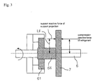
- a support projection 71 which is brought into contact with the rear surface of the rotor 61 and defines the maximum tilt angle limit of the swash plate 7, is formed on a position of the front surface of the swash plate 7.
- the tilt angle of the swash plate 7 with regard to the drive shaft 6 is adjusted according to the pressure changes of suction pressure in the rear housing 4 caused by the operation of a control valve 8.
- the operation of the swash plate type compressor is described, hereinafter.
- the pistons 2 arranged in a circle in the cylinder block 1 are sequentially reciprocated by the rotation of the swash plate 7.
- the suction lead valve of the valve unit 5 is opened by a pressure drop in the bore 11 and the bore 11 communicates with the suction chamber 41, thereby allowing refrigerant to flow from the suction chamber 41 to the bore 11.
- the swash plate 7 is rotated and the positions of the pistons 2 in their strokes are different, so forces exerted on the swash plate 7 by the pistons 2 are different according to the positions of the swash plate 7 where the pistons 2 are engaged with the swash plate 7. Additionally, as shown in Fig.
- the support projection 71 defining the maximum tilt angle limit of the swash plate 7 is situated on a connecting line LC passing through the center P1 of the piston 2 in the maximum compression stroke state (that is, the center P1 of the piston 2 at the central position of the upper portion of the swash plate 7, or the center of the bore 11 to which this piston 2 is inserted) and the center P2 of the drive shaft 6 on the front surface of the swash plate 7.
- an acting point P4 of the maximum compression reactive force exerted on the swash plate 7 by the pistons 2 is situated at no a position corresponding to the first point P1 but a position that is spaced apart from the first point P1 by a certain distance L in the rotational direction of the swash plate 7 (see Fig. 8).
- eccentric load is exerted on the swash plate 7, thereby damaging the swash plate 7 to be bent, deformed or the like. Additionally, when the swash plate 7 is further rotated while being deformed, eccentric wear occurs, thereby creating a loud noise. Additionally, there occurs a problem that the concentration of stress is produced on the hinge unit 64 of the swash plate 7 and the rotor 61.
- an object of the present invention is to provide a structure for supporting a swash plate at the maximum tilt angle in a swash plate type compressor, which is capable of effectively preventing the swash plate from being damaged by preventing eccentric load from acting on the swash plate.
- the present invention provides a structure for supporting a swash plate at the maximum tilt angle in a swash plate type compressor, in which the swash plate is fitted around a drive shaft by support means to be swung, the peripheral edge of the swash plate is rotatably inserted into the bridges of pistons movably inserted into a plurality of bores formed in a cylinder, the central portion of the upper portion of the front surface of the swash plate is attached by a hinge unit to a rotor fixedly attached around the drive shaft, the center of the hinge unit coincides with the center of the a bore into which a piston at its maximum compression stroke state is inserted, and a support projection is formed at a predetermined position of the front surface of the swash plate to define the maximum tilt angle limit by coming into contact with the rotor, characterized in that: when a connecting line passing through the center of the bore, into which the piston in the maximum compression stroke state is inserted, designated by LC, the support projection is
- a diameter of a circle passing through centers of the bores is designated by R, the horizontal distance LF may be in a range of 0.35R to 0.43R.
- reference numeral 1 designates the cylinder block of a variable displacement swash plate type compressor.
- a plurality of bores 11 are circumferentially arranged, and each extended longitudinally to pass through the cylinder block 1 in a longitudinal direction.
- a plurality of pistons each provided at its front end with a bridge 21 are each inserted into each of bores 11 to be reciprocated.
- a front housing 3 is attached to the front end of the cylinder block 1, and a rear housing 4 is attached to the rear end of the cylinder block 1.
- the front housing 3, the cylinder block 1 and the rear housing 4 can be secured to one another by a plurality of bolts 13.
- the front surface of the front housing 3 is closed while its rear surface is open, so an interior space defined by the cylinder block 1 and the front housing 3 functions as a crank chamber 31.
- the front surface of the rear housing 4 is closed while its rear surface is open, so an interior space is formed in the rear housing 4 by the cylinder block 1 and the rear housing 4.
- the interior space of the rear housing 4 is partitioned into a refrigerant sucking chamber 41 connected to an evaporator and a discharge chamber 42 connected to a condenser.
- a valve unit 5 is interposed between the cylinder block 1 and the rear housing 4.
- the valve unit 5 is operated in such a way that during the suction stroke of a piston 2 the refrigerant sucking chamber 41 communicates with a bore 11 to suck refrigerant from the refrigerant sucking chamber 41, while during the compression stroke of the piston 2 the bore 11 communicates with the discharge chamber 42 to discharge compressed refrigerant to the discharge chamber 42.
- Reference numeral 6 designates a drive shaft, which penetrates the center portion of the front housing 3, passes through the crank chamber 31 formed in the interior of the front housing 3 and be rotatably supported at its rear end by the center portion of the cylinder block 1.
- a rotor 61 is fitted around the drive shaft 6 in the front portion of the interior of the crank chamber 31. Accordingly, with the rotation of the drive shaft 6, the rotor 61 is rotated at the same time.
- a swash plate 7 is fitted around the drive shaft 6 in the crank chamber 31 to be swung and rotated.
- the swash plate 7 can be mounted to be swung and rotated by support means, such as a bearing or support pin, interposed between the drive shaft 6 and the swash plate 7.
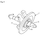
- the swash plate 7, as shown in Figs. 1 and 2 is comprised of a hub plate 7a provided with a center hole and mounted around the drive shaft 6 to be swung and rotated by the support means 63, and a drive disk 7b integrally and fixedly fitted around the hub plate 7a.
- the peripheral portion of the swash plate 7, that is, the peripheral portion of the drive disk 7b, is rotatably inserted into the bridges 21 of the pistons 21.
- the center portion of the upper portion of the front surface of the swash plate 7 is hingedly connected to the rotor 61.
- the tilt angle with regard to the drive shaft 6 is preferably adjusted by the swing of the swash plate 7 around a hinge unit 64.
- a yoke 73 is formed on the center portion of the upper portion of the front surface of the swash plate 7 (that is, the center portion of the upper portion of the front surface of the hub plate 7a), a connecting projection 611 is formed on the central portion of the upper portion of the rear surface of the rotor 61, and the yoke 73 and the connecting projection 611 are hingedly connected to each other by a hinge pin 65.
- the swash plate 7 is swung around the hinge unit 64 (that is, the hinge pin 65), so the tilt angle of the swash plate 7 with regard to the drive shaft 6 can be adjusted, and the swash plate 7 can be rotated by the transmission of the rotating force of the rotor 61 to the swash plate 7 through the hinge unit 64.
- the tilt adjustment of the swash plate 7 by the swing of the swash plate 7 is performed according to pressure changes in the crank chamber 31, and the pressure changes in the crank chamber 31 are performed by the operation of the control valve 8 mounted on the rear housing 4. That is, the control valve 8 adjusts the amount of refrigerant discharged from a compressor by changing the tilt angle of the swash plate 7 by means of adjusting the pressure of the interior of the crank chamber 31 according to the suction pressure of refrigerant returned to the compressor so as to keep the suction pressure of the compressor constant.
- the phase of the swash plate 7 is continuously changed with regard to each piston 2.
- the support projection 71 which defines the maximum tilt angle of the swash plate 7 by contact with the rotor 61, is projected from a position of the front surface of the swash plate 7 (in more detail, the front surface of the hub plate 7a) toward the rotor 61.
- the front surface of the support projection 71 to be brought into contact with the rotor 61 is preferably inclined with regard to the front surface of the swash plate 7 to correspond to the surface of the rotor 61.
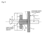
- the swash plate 7 should be swung with regard to the drive shaft 6 around the hinge pin 65 of the hinge unit 64, so a bore 11, into which the piston 2 in its maximum compression stroke state is inserted when the swash plate 7 maintains its maximum tilt angle, should be arranged. Additionally, in such a state, the maximum reactive force exerted on the swash plate 7 by the pistons 2 seems to be situated at a position P1 (first point) corresponding to the center of the bore 11 into which the piston 2 in its maximum compression stroke state is inserted.
- the support projection 71 for maintaining the maximum tilt angle of the swash plate 7 seems to be situated at an optional position P3(a third point) on a connecting line LC connecting the first point P1 and the center P2 (a second point) on the front surface of the swash plate 7.
- the swash plate 7 is rotated, and the positions of the pistons 2 in their strokes are different according to the positions where the pistons 2 are engaged with the swash plate 7.
- the support projection 71 is positioned on an acting line LP, which vertically passes through the action point P4 of the maximum reactive force and is spaced apart from the connecting line LC by a distance LF, thereby preventing the maximum reactive force from causing eccentric load to the swash plate 7.
- the compressor having seven bores 11 is disclosed.
- the pistons 2 in a compression stroke state are designated by Pd
- the pistons 2 in a suction stroke state are designated by Ps
- the pistons 2 in an intermediate state are designated by Pi.
- Pressure exerted on the swash plate 7 is the largest on the portions of the swash plate 7 corresponding to the pistons Pd in the compression stroke state, intermediate on the portions of the swash plate 7 corresponding to the pistons Pi, and the smallest on the portions of the swash plate 7 corresponding to the pistons Ps.
- the support projection 71 defines the maximum tilt angle of the swash plate 7 while being situated on the acting line LP that is spaced apart from the connecting line LC by the horizontal distance LF of 0.35R to 0.43R in the rotating direction of the swash plate 7.
- the support projection 71 may be positioned at an optional position where the horizontal distance LF away from the connecting line LC satisfies a relation of LF ⁇ 0.35R
- the support projection 71 is not formed on the connecting line LC connecting three points P1, P2 and P3, but formed on the acting line LP that is spaced apart from the connecting line LC by the horizontal distance LF.
- the action point of the maximum reactive force and the position of the support projection 71 are opposite to each other on both sides of the swash plate 7, so eccentric load is not exerted on the swash plate 7, thereby preventing the swash plate 7 from being damaged as being bent, deformed or the like.
- the present invention provides a structure for supporting a swash plate at the maximum tilt angle in a swash plate type compressor, in which a support projection 71 and the acting point P3 of the maximum reactive force are situated on the acting line LP spaced apart from the connecting line LC, so the maximum compression reactive force of refrigerant and the support reactive force of the support projection 71 are opposite. Accordingly, eccentric load is not exerted on the swash plate 7, so the swash plate 7 can be prevented from being damaged as being bent or deformed.
- the swash plate 7 can be quietly rotated, thereby reducing the noise of the compressor.
Landscapes
- Engineering & Computer Science (AREA)
- Mechanical Engineering (AREA)
- General Engineering & Computer Science (AREA)
- Compressors, Vaccum Pumps And Other Relevant Systems (AREA)
Applications Claiming Priority (2)
| Application Number | Priority Date | Filing Date | Title |
|---|---|---|---|
| KR2000032186 | 2000-06-12 | ||
| KR1020000032186A KR100352877B1 (ko) | 2000-06-12 | 2000-06-12 | 압축기 사판의 최대경사각 지지구조 |
Publications (3)
| Publication Number | Publication Date |
|---|---|
| EP1164288A2 true EP1164288A2 (fr) | 2001-12-19 |
| EP1164288A3 EP1164288A3 (fr) | 2002-11-20 |
| EP1164288B1 EP1164288B1 (fr) | 2006-05-17 |
Family
ID=36571430
Family Applications (1)
| Application Number | Title | Priority Date | Filing Date |
|---|---|---|---|
| EP01114161A Expired - Lifetime EP1164288B1 (fr) | 2000-06-12 | 2001-06-11 | Pivot pour un plateau en biais d'un compresseur à capacité variable |
Country Status (6)
| Country | Link |
|---|---|
| US (1) | US6553890B2 (fr) |
| EP (1) | EP1164288B1 (fr) |
| JP (1) | JP3680097B2 (fr) |
| KR (1) | KR100352877B1 (fr) |
| DE (1) | DE60119623T2 (fr) |
| PT (1) | PT1164288E (fr) |
Families Citing this family (9)
| Publication number | Priority date | Publication date | Assignee | Title |
|---|---|---|---|---|
| DE60136128D1 (de) * | 2000-06-19 | 2008-11-27 | Toyota Jidoshokki Kariya Kk | Taumelscheibenverdichter |
| US7446592B2 (en) * | 2005-07-22 | 2008-11-04 | Freescale Semiconductor, Inc. | PVT variation detection and compensation circuit |
| JP4976731B2 (ja) | 2006-04-07 | 2012-07-18 | カルソニックカンセイ株式会社 | 可変容量圧縮機 |
| JP2008184933A (ja) * | 2007-01-29 | 2008-08-14 | Sanden Corp | 斜板式圧縮機 |
| KR101740037B1 (ko) | 2010-03-10 | 2017-06-26 | 학교법인 두원학원 | 용량 가변형 사판식 압축기 |
| FR2975606B1 (fr) | 2011-05-25 | 2013-05-31 | Air Liquide | Equipement pour l'injection d'un gaz dans un bassin d'epuration |
| JP6171875B2 (ja) * | 2013-11-13 | 2017-08-02 | 株式会社豊田自動織機 | 可変容量型斜板式圧縮機 |
| US9816377B2 (en) * | 2014-09-24 | 2017-11-14 | Eaton Corporation | Hydraulic axial-piston device with features to enhance efficiency and power density |
| WO2020022749A1 (fr) * | 2018-07-23 | 2020-01-30 | Samsung Electronics Co., Ltd. | Appareil d'alimentation en air froid et réfrigérateur le comportant |
Family Cites Families (9)
| Publication number | Priority date | Publication date | Assignee | Title |
|---|---|---|---|---|
| JP3259487B2 (ja) | 1993-12-06 | 2002-02-25 | 株式会社豊田自動織機 | 容量可変型斜板式圧縮機 |
| JP3404909B2 (ja) | 1994-09-12 | 2003-05-12 | 株式会社豊田自動織機 | 可変容量型斜板式圧縮機における斜板傾動案内構造 |
| JPH09112420A (ja) * | 1995-10-19 | 1997-05-02 | Toyota Autom Loom Works Ltd | 可変容量圧縮機 |
| JPH10246181A (ja) * | 1997-02-28 | 1998-09-14 | Toyota Autom Loom Works Ltd | 可変容量型圧縮機 |
| JP3826473B2 (ja) * | 1997-02-28 | 2006-09-27 | 株式会社豊田自動織機 | 可変容量型圧縮機 |
| JPH10266952A (ja) | 1997-03-25 | 1998-10-06 | Zexel Corp | 可変容量型斜板式圧縮機 |
| JPH11201032A (ja) * | 1998-01-13 | 1999-07-27 | Toyota Autom Loom Works Ltd | 可変容量型圧縮機 |
| US6139283A (en) * | 1998-11-10 | 2000-10-31 | Visteon Global Technologies, Inc. | Variable capacity swash plate type compressor |
| JP2000329062A (ja) * | 1999-05-19 | 2000-11-28 | Toyota Autom Loom Works Ltd | 可変容量型圧縮機における容量制御構造 |
-
2000
- 2000-06-12 KR KR1020000032186A patent/KR100352877B1/ko not_active Expired - Lifetime
-
2001
- 2001-06-11 DE DE60119623T patent/DE60119623T2/de not_active Expired - Lifetime
- 2001-06-11 PT PT01114161T patent/PT1164288E/pt unknown
- 2001-06-11 EP EP01114161A patent/EP1164288B1/fr not_active Expired - Lifetime
- 2001-06-12 US US09/879,278 patent/US6553890B2/en not_active Expired - Lifetime
- 2001-06-12 JP JP2001177628A patent/JP3680097B2/ja not_active Expired - Fee Related
Also Published As
| Publication number | Publication date |
|---|---|
| DE60119623T2 (de) | 2007-04-26 |
| KR20010111643A (ko) | 2001-12-20 |
| JP3680097B2 (ja) | 2005-08-10 |
| US6553890B2 (en) | 2003-04-29 |
| EP1164288A3 (fr) | 2002-11-20 |
| EP1164288B1 (fr) | 2006-05-17 |
| KR100352877B1 (ko) | 2002-09-16 |
| PT1164288E (pt) | 2006-09-29 |
| US20010049997A1 (en) | 2001-12-13 |
| DE60119623D1 (de) | 2006-06-22 |
| JP2002048056A (ja) | 2002-02-15 |
Similar Documents
| Publication | Publication Date | Title |
|---|---|---|
| JPH05172052A (ja) | 可変容量斜板式圧縮機 | |
| EP1001169A3 (fr) | Compresseur à plateau en biais à capacité variable | |
| US6553890B2 (en) | Structure for supporting a swash plate at the maximum tilt angle in a variable displacement swash plate type compressor | |
| US6524079B1 (en) | Alignment means for the swash plate of a variable-capacity swash-plate type compressor | |
| US6572342B2 (en) | Variable capacity compressor and method of manufacturing | |
| US6604447B2 (en) | Swash plate-type variable displacement compressor | |
| CN1070989A (zh) | 用于压缩机壳体的密封构件 | |
| KR100382362B1 (ko) | 가변용량 사판식 압축기 | |
| US6212995B1 (en) | Variable-displacement inclined plate compressor | |
| CN101512151A (zh) | 可变容量压缩机 | |
| US6912948B2 (en) | Swash plate compressor | |
| KR20090118513A (ko) | 사판식 압축기 | |
| KR100779068B1 (ko) | 사판식 압축기 | |
| KR101740037B1 (ko) | 용량 가변형 사판식 압축기 | |
| JPH07279840A (ja) | 斜板式可変容量圧縮機 | |
| KR100519745B1 (ko) | 용량가변형 사판식 압축기 | |
| US20090148312A1 (en) | Variable Capacity Swash Plate Type Compressor | |
| JP2001020858A (ja) | 可変容量型圧縮機 | |
| KR101179588B1 (ko) | 사판식 압축기 | |
| JP3099508B2 (ja) | 斜板型可変容量圧縮機 | |
| JP3080265B2 (ja) | 斜板式圧縮機 | |
| KR20080055117A (ko) | 가변용량형 사판식 압축기 | |
| JP4264880B2 (ja) | 可変容量型斜板式圧縮機 | |
| JPH03194171A (ja) | 連続可変容量型圧縮機 | |
| KR20040020294A (ko) | 가변용량 사판식 압축기 |
Legal Events
| Date | Code | Title | Description |
|---|---|---|---|
| PUAI | Public reference made under article 153(3) epc to a published international application that has entered the european phase |
Free format text: ORIGINAL CODE: 0009012 |
|
| AK | Designated contracting states |
Kind code of ref document: A2 Designated state(s): AT BE CH CY DE DK ES FI FR GB GR IE IT LI LU MC NL PT SE TR |
|
| AX | Request for extension of the european patent |
Free format text: AL;LT;LV;MK;RO;SI |
|
| PUAL | Search report despatched |
Free format text: ORIGINAL CODE: 0009013 |
|
| AK | Designated contracting states |
Kind code of ref document: A3 Designated state(s): AT BE CH CY DE DK ES FI FR GB GR IE IT LI LU MC NL PT SE TR |
|
| AX | Request for extension of the european patent |
Free format text: AL;LT;LV;MK;RO;SI |
|
| 17P | Request for examination filed |
Effective date: 20030509 |
|
| AKX | Designation fees paid |
Designated state(s): DE FR GB IT PT SE |
|
| 17Q | First examination report despatched |
Effective date: 20030805 |
|
| GRAP | Despatch of communication of intention to grant a patent |
Free format text: ORIGINAL CODE: EPIDOSNIGR1 |
|
| GRAS | Grant fee paid |
Free format text: ORIGINAL CODE: EPIDOSNIGR3 |
|
| GRAA | (expected) grant |
Free format text: ORIGINAL CODE: 0009210 |
|
| AK | Designated contracting states |
Kind code of ref document: B1 Designated state(s): DE FR GB IT PT SE |
|
| REG | Reference to a national code |
Ref country code: GB Ref legal event code: FG4D |
|
| REF | Corresponds to: |
Ref document number: 60119623 Country of ref document: DE Date of ref document: 20060622 Kind code of ref document: P |
|
| REG | Reference to a national code |
Ref country code: SE Ref legal event code: TRGR |
|
| REG | Reference to a national code |
Ref country code: PT Ref legal event code: SC4A Effective date: 20060713 |
|
| ET | Fr: translation filed | ||
| PLBE | No opposition filed within time limit |
Free format text: ORIGINAL CODE: 0009261 |
|
| STAA | Information on the status of an ep patent application or granted ep patent |
Free format text: STATUS: NO OPPOSITION FILED WITHIN TIME LIMIT |
|
| 26N | No opposition filed |
Effective date: 20070220 |
|
| REG | Reference to a national code |
Ref country code: DE Ref legal event code: R082 Ref document number: 60119623 Country of ref document: DE Representative=s name: KOEPE & PARTNER, DE |
|
| REG | Reference to a national code |
Ref country code: FR Ref legal event code: CD Owner name: HALLA VISTEON CLIMATE CONTROL CORPORATION Effective date: 20130827 |
|
| REG | Reference to a national code |
Ref country code: DE Ref legal event code: R082 Ref document number: 60119623 Country of ref document: DE Representative=s name: KOEPE & PARTNER, DE Effective date: 20130910 Ref country code: DE Ref legal event code: R081 Ref document number: 60119623 Country of ref document: DE Owner name: HALLA VISTEON CLIMATE CONTROL CORP., KR Free format text: FORMER OWNER: HALLA CLIMATE CONTROL CORP., TAEJON, KR Effective date: 20130910 Ref country code: DE Ref legal event code: R082 Ref document number: 60119623 Country of ref document: DE Representative=s name: SCHWABE SANDMAIR MARX PATENTANWAELTE RECHTSANW, DE Effective date: 20130910 Ref country code: DE Ref legal event code: R081 Ref document number: 60119623 Country of ref document: DE Owner name: HANON SYSTEMS, KR Free format text: FORMER OWNER: HALLA CLIMATE CONTROL CORP., TAEJON, KR Effective date: 20130910 |
|
| REG | Reference to a national code |
Ref country code: FR Ref legal event code: PLFP Year of fee payment: 16 |
|
| REG | Reference to a national code |
Ref country code: DE Ref legal event code: R082 Ref document number: 60119623 Country of ref document: DE Representative=s name: SSM SANDMAIR PATENTANWAELTE RECHTSANWALT PARTN, DE Ref country code: DE Ref legal event code: R082 Ref document number: 60119623 Country of ref document: DE Representative=s name: SCHWABE SANDMAIR MARX PATENTANWAELTE RECHTSANW, DE |
|
| REG | Reference to a national code |
Ref country code: DE Ref legal event code: R082 Ref document number: 60119623 Country of ref document: DE Representative=s name: SSM SANDMAIR PATENTANWAELTE RECHTSANWALT PARTN, DE Ref country code: DE Ref legal event code: R082 Ref document number: 60119623 Country of ref document: DE Representative=s name: SCHWABE SANDMAIR MARX PATENTANWAELTE RECHTSANW, DE Ref country code: DE Ref legal event code: R081 Ref document number: 60119623 Country of ref document: DE Owner name: HANON SYSTEMS, KR Free format text: FORMER OWNER: HALLA VISTEON CLIMATE CONTROL CORP., DAEJEON, KR |
|
| REG | Reference to a national code |
Ref country code: FR Ref legal event code: CD Owner name: HANON SYSTEMS Effective date: 20161212 |
|
| REG | Reference to a national code |
Ref country code: FR Ref legal event code: PLFP Year of fee payment: 17 |
|
| REG | Reference to a national code |
Ref country code: FR Ref legal event code: PLFP Year of fee payment: 18 |
|
| PGFP | Annual fee paid to national office [announced via postgrant information from national office to epo] |
Ref country code: DE Payment date: 20200527 Year of fee payment: 20 Ref country code: FR Payment date: 20200512 Year of fee payment: 20 |
|
| PGFP | Annual fee paid to national office [announced via postgrant information from national office to epo] |
Ref country code: IT Payment date: 20200512 Year of fee payment: 20 Ref country code: GB Payment date: 20200603 Year of fee payment: 20 Ref country code: SE Payment date: 20200610 Year of fee payment: 20 |
|
| PGFP | Annual fee paid to national office [announced via postgrant information from national office to epo] |
Ref country code: PT Payment date: 20200705 Year of fee payment: 20 |
|
| REG | Reference to a national code |
Ref country code: DE Ref legal event code: R071 Ref document number: 60119623 Country of ref document: DE |
|
| REG | Reference to a national code |
Ref country code: GB Ref legal event code: PE20 Expiry date: 20210610 |
|
| PG25 | Lapsed in a contracting state [announced via postgrant information from national office to epo] |
Ref country code: PT Free format text: LAPSE BECAUSE OF EXPIRATION OF PROTECTION Effective date: 20210621 |
|
| REG | Reference to a national code |
Ref country code: SE Ref legal event code: EUG |
|
| PG25 | Lapsed in a contracting state [announced via postgrant information from national office to epo] |
Ref country code: GB Free format text: LAPSE BECAUSE OF EXPIRATION OF PROTECTION Effective date: 20210610 |