EP1164309A2 - Geformte Luftbälge - Google Patents
Geformte Luftbälge Download PDFInfo
- Publication number
- EP1164309A2 EP1164309A2 EP01112903A EP01112903A EP1164309A2 EP 1164309 A2 EP1164309 A2 EP 1164309A2 EP 01112903 A EP01112903 A EP 01112903A EP 01112903 A EP01112903 A EP 01112903A EP 1164309 A2 EP1164309 A2 EP 1164309A2
- Authority
- EP
- European Patent Office
- Prior art keywords
- sleeve
- air
- ply
- air sleeve
- accordance
- Prior art date
- Legal status (The legal status is an assumption and is not a legal conclusion. Google has not performed a legal analysis and makes no representation as to the accuracy of the status listed.)
- Granted
Links
- 230000002787 reinforcement Effects 0.000 claims abstract description 55
- 230000003014 reinforcing effect Effects 0.000 claims abstract description 20
- 150000001875 compounds Chemical class 0.000 claims abstract description 10
- 229920001971 elastomer Polymers 0.000 claims description 42
- 239000000835 fiber Substances 0.000 claims description 28
- 239000000806 elastomer Substances 0.000 claims description 24
- 238000000034 method Methods 0.000 claims description 21
- 239000005060 rubber Substances 0.000 claims description 18
- 239000004744 fabric Substances 0.000 claims description 12
- 239000002759 woven fabric Substances 0.000 claims description 2
- 239000010410 layer Substances 0.000 description 66
- 239000000463 material Substances 0.000 description 9
- 239000002184 metal Substances 0.000 description 8
- 229910052751 metal Inorganic materials 0.000 description 8
- 238000004519 manufacturing process Methods 0.000 description 6
- 230000035939 shock Effects 0.000 description 6
- 238000000465 moulding Methods 0.000 description 5
- 239000006096 absorbing agent Substances 0.000 description 4
- 238000010276 construction Methods 0.000 description 4
- 239000000725 suspension Substances 0.000 description 3
- 229920000742 Cotton Polymers 0.000 description 2
- 239000004677 Nylon Substances 0.000 description 2
- 229920002367 Polyisobutene Polymers 0.000 description 2
- 229920000297 Rayon Polymers 0.000 description 2
- 239000004760 aramid Substances 0.000 description 2
- 229920003235 aromatic polyamide Polymers 0.000 description 2
- 238000003490 calendering Methods 0.000 description 2
- 229920001778 nylon Polymers 0.000 description 2
- 229920000728 polyester Polymers 0.000 description 2
- 239000002964 rayon Substances 0.000 description 2
- OKTJSMMVPCPJKN-UHFFFAOYSA-N Carbon Chemical compound [C] OKTJSMMVPCPJKN-UHFFFAOYSA-N 0.000 description 1
- BRLQWZUYTZBJKN-UHFFFAOYSA-N Epichlorohydrin Chemical compound ClCC1CO1 BRLQWZUYTZBJKN-UHFFFAOYSA-N 0.000 description 1
- 244000043261 Hevea brasiliensis Species 0.000 description 1
- 239000005062 Polybutadiene Substances 0.000 description 1
- 229910000831 Steel Inorganic materials 0.000 description 1
- 239000002174 Styrene-butadiene Substances 0.000 description 1
- 239000012790 adhesive layer Substances 0.000 description 1
- MTAZNLWOLGHBHU-UHFFFAOYSA-N butadiene-styrene rubber Chemical compound C=CC=C.C=CC1=CC=CC=C1 MTAZNLWOLGHBHU-UHFFFAOYSA-N 0.000 description 1
- 229910052799 carbon Inorganic materials 0.000 description 1
- 239000011248 coating agent Substances 0.000 description 1
- 238000000576 coating method Methods 0.000 description 1
- 230000001010 compromised effect Effects 0.000 description 1
- 239000011521 glass Substances 0.000 description 1
- 239000000203 mixture Substances 0.000 description 1
- 229920003052 natural elastomer Polymers 0.000 description 1
- 229920001194 natural rubber Polymers 0.000 description 1
- 229920001084 poly(chloroprene) Polymers 0.000 description 1
- 229920002857 polybutadiene Polymers 0.000 description 1
- 229920001195 polyisoprene Polymers 0.000 description 1
- 239000012783 reinforcing fiber Substances 0.000 description 1
- 238000007789 sealing Methods 0.000 description 1
- 239000010959 steel Substances 0.000 description 1
- 238000005728 strengthening Methods 0.000 description 1
- 239000011115 styrene butadiene Substances 0.000 description 1
- 229920003048 styrene butadiene rubber Polymers 0.000 description 1
- 239000004753 textile Substances 0.000 description 1
Images



Classifications
-
- F—MECHANICAL ENGINEERING; LIGHTING; HEATING; WEAPONS; BLASTING
- F16—ENGINEERING ELEMENTS AND UNITS; GENERAL MEASURES FOR PRODUCING AND MAINTAINING EFFECTIVE FUNCTIONING OF MACHINES OR INSTALLATIONS; THERMAL INSULATION IN GENERAL
- F16F—SPRINGS; SHOCK-ABSORBERS; MEANS FOR DAMPING VIBRATION
- F16F9/00—Springs, vibration-dampers, shock-absorbers, or similarly-constructed movement-dampers using a fluid or the equivalent as damping medium
- F16F9/02—Springs, vibration-dampers, shock-absorbers, or similarly-constructed movement-dampers using a fluid or the equivalent as damping medium using gas only or vacuum
- F16F9/04—Springs, vibration-dampers, shock-absorbers, or similarly-constructed movement-dampers using a fluid or the equivalent as damping medium using gas only or vacuum in a chamber with a flexible wall
- F16F9/0409—Springs, vibration-dampers, shock-absorbers, or similarly-constructed movement-dampers using a fluid or the equivalent as damping medium using gas only or vacuum in a chamber with a flexible wall characterised by the wall structure
Definitions
- the present invention relates to molded air sleeves. More particularly, the present invention relates to a method of construction and manufacturing of molded air sleeves to achieve a desired construction at the end of the air sleeve.
- Air sleeves have a rubber innerliner, two plies of cord fabric, and a rubber cover. These sleeves see their greatest commercial usage in the automotive helper spring market by being mounted as air springs on shock absorbers and struts. Other uses include truck cab suspension springs, truck driver seat springs, automobile air springs, and a variety of industrial air springs.
- the air sleeves are manufactured with a variety of ends, but these ends fall into two basic constructions: those with the ending of the cord plies exposed to the air (usually a cut end), and those where the endings of the cord plies must be completely encased in rubber, called a 'sealed end'.
- enclosing the cord endings in rubber is very important if the end of the sleeve is exposed to the high pressure air chamber of the air spring, where exposed cord ply ends may lead to sleeve failure due to high pressure air entering the exposed cord endings and migrating into the body of the air sleeve.
- some sealed end air sleeves require not only that the cord endings be placed within 0.20" or less (5.1 mm or less) of the end of the part, but also require a chamfered angle on the end of the part of typically 30° to 60°, which reduces the thickness of the end of the part by up to 50%.
- the combined requirement for cords to be adjacent to the end and the chamfered shape can make it very difficult to reliably seal the cord endings during the molding process because of the loss of covering rubber due to the chamfer.
- the molding process uses an inflatable bladder on one side of the part and a metal mold on the other side of the part, significant movement of the end areas of the air sleeve as the bladder inflates can occur. This can lead to the cord endings drifting toward one surface of the part, while the elastomer is soft and flowing. This may result in unreliable sealing of the cord endings.
- the present invention is directed towards an air sleeve and a method of forming such, as defined in the claims.
- the air sleeve has a tubular shape with opposing sleeve ends. At least one reinforcing ply extends from one sleeve end to the opposing sleeve end; the reinforcing ply has cords encapsulated in a ply coat compound and at least one end of the reinforcing ply terminates in one air sleeve end.
- the reinforcement means is preferably an additional reinforcing layer and is spaced from the end of the reinforcing ply by a distance greater than the thickness of the ply coat compound.
- the reinforcement means is selected from the group consisting of fiber loaded elastomer, woven fabric ply, knitted fabric ply, spun-bonded ply, and cord reinforced ply.
- the reinforcement means is a fiber loaded rubber
- the elastomer is comprised of 1.5 to 10 phr, preferably 6 phr (parts per hundred rubber) of chopped fibers.
- the fibers have a nominal length of 1/16 inch to 1/4 inch (1.5 mm to 6.5 mm).
- both opposing ends of the air sleeve are provided with the reinforcement means.
- FIG. 1 illustrates an air sleeve 2 of the type to be used in a pneumatic shock absorber or strut.
- the sleeve 2 is positioned with one sleeve end 10 flipped up, the sleeve 2 being ready to be mounted in a strut or shock absorber.
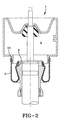
- one sleeve end 6 is restrained within the pressure chamber 8 created within the shock absorber 4, while the other sleeve end 10 is restrained outside of the pressure chamber 8, as illustrated in FIG 2.
- the sleeve end 10 restrained outside of the pressure chamber 8 is a cut end, while the sleeve end 6 restrained inside the chamber 8 is a sealed end.
- the sealed end 6 of the air sleeve 2 is formed with an additional reinforcement layer 12, see FIGS 3A to 3C.
- the reinforcement layer 12A, 12B, 12C is located at the sleeve end, and is distanced from the end 26 of the reinforcing plies 18, 19 by a distance t.
- the distance t is measured as the smallest distance between the reinforcement layer 12 and the end 26 of the reinforcement plies 18, 19.
- the distance t is greater than the thickness P of the ply coat covering the cords 27 of the reinforcing plies 18, 19.
- the reinforcement layer 12 may be placed in variety of locations in the sealed end 6 of the sleeve 2, and the exact location and configuration of the reinforcement layer 12 is not limited by the few specific illustrations.
- the additional reinforcement layer 12 aids in the manufacture of the air sleeve 2 and ensures the desired configuration of the sleeve end 6, as well as provides additional strengthening at the sleeve end 6.
- the reinforcement layer 12A is a relatively thick fiber loaded rubber layer that is distanced from the reinforcing plies by a distance t that is approximately one-half the thickness of the reinforcing layer 12A.
- the reinforcement layer 12B is a thin cord reinforced layer. The reinforcement layer 12B is located along the surface of the sleeve end 6.
- the reinforcement layer 12C is a fiber loaded rubber layer that is encompassed within the sleeve end 6.
- the reinforcement layer 12 may be constructed from different materials, and may be placed in a variety of configurations in the sleeve end other than just the specific illustrated examples. Other configurations can also include wrapping the entire end 6 of the sleeve 2 (i.e. U-shaped wrapping to cover the end) and having the reinforcement layer 12 extend along only one side of the sleeve.
- the first step in manufacturing the flexible shaped air sleeves 2 is the building of an uncured tubular preform. Any efficient method for plying up the layers of the tubular preform is suitable.
- a preferred automated method is disclosed in U.S. Patent No. 3,794,538, and is illustrated in FIG. 4.
- two sleeves are simultaneously prepared on a rotatable mandrel 14, the length of the mandrel being greater than twice the length of the airsleeve 2 being prepared.
- the individual components of the airsleeve 2 are laid upon a moving belt 16 that facilitates material handling during the sleeve buildup.
- the components laid upon the belt 16 are also of a length twice the necessary length of a single airsleeve 2 being prepared.
- the conventional components laid upon the belt 16 are at least one reinforcement ply 18, 19 and a cover layer 20. Adjacent to the cover layer 20 is the reinforcement layer 12, centrally located on the moving belt 16. The width of the reinforcement layer 12 is twice the width required for each end of the airsleeve 2 to be manufactured.
- the innermost rubber layer 24 is extruded in a separate operation, slightly expanded and slipped over the rotatable mandrel 14.
- the first ply 18 is spirally applied to the mandrel 14, overlying the innermost rubber layer 24 by means of the rotating mandrel 14 and the moving belt 16.
- the second ply 19 is spirally wound in an opposite sense over the first fabric layer 18.
- the fabric plies 18, 19 contain bias cut cords that have their cords running in opposite directions.
- the cords of the plies 18, 19 are encapsulated in a ply coat compound to form the plies 18, 19.
- tubular preform may be comprised of any of a large variety of textile cords, or even fabrics if desired, and that the particular bias angles of the cords in the plies 18, 19 are determined by the type of air sleeve 2 being manufactured.
- the cover layer 20 of calendered rubber is applied over the underlying layers 24, 18, 19.
- the reinforcement layer 22 is wound centrally onto the cover layer 20.
- one preform end has the additional reinforcement layer 22 while the opposing preform end does not. While not illustrated, both preform ends may be provided with the additional reinforcement layer 22.
- additional reinforcement layers 22 may be laid upon the moving belt 16 adjacent to the central reinforcement layer 22, or may be applied in any other reasonable method. After the preform has been assembled and cut to the proper length, with the reinforcement layer 22 located at least one of the preform ends, the preform is cured to form the air sleeve 2.
- Alternative methods of constructing the preform include, but are not limited to, plying up the materials required to manufacture only one sleeve, applying the reinforcement layer 22 to the rotatable mandrel 14 before the innermost rubber layer 24 is applied to the mandrel 14, or applying the reinforcement layers 22 only at the ends of the double length preform.
- the reinforcement layer may be provided from a plurality of different types of materials. As shown in FIGS. 3A and 3C the reinforcement layer 12A, 12C is a fiber-reinforced elastomer.
- the elastomeric base is selected from among elastomers conventionally used in manufacturing air sleeves, included, but not limited to elastomers such as polychloroprene, poly-epichlorohydrin, polyisobutylene, halogenated-polyisobutylene, natural rubber, polyisoprene, polybutadiene, styrene-butadiene, and blends of such elastomers.
- the elastomer base of the reinforcement layer 12A, 12C is from the same family as the elastomer used to form the cover layer 20 so that the reinforcement layer 12A, 12C will readily bond with the cover layer 20 upon curing of the preform to form the sleeve 2.
- the elastomer is provided with about 1.0 to 10 phr of fiber, preferably 1.5 to 6.0 phr, with a preferred loading of 6.0 phr.
- the fibers are short fibers, with a nominal length ranging from about 1/16 inch to about 1 ⁇ 4 inch (1.5 mm to 6.5 mm), with a preferred length of about 3/16 inch (4.75 mm).
- the fibers may or may not be oriented in the reinforcement layer 12A, 12C.
- the fibers are of any conventional reinforcing fiber material, such as cotton, nylon, rayon polyester, aramid, glass, metal, steel, or carbon.
- the reinforcement layer 12B may also be formed from a fabric or cord layer. If the reinforcement layer 12B is a fabric layer, it may be woven, knitted, or spun bonded from materials such as rayon, nylon, polyester, aramid, or cotton, or a combination of such materials. Preferably, the fabric has a thin gauge. Or the reinforcement layer 12B may be a calendered cord layer formed from the same materials as a fabric layer. An adhesive layer may be applied in the conventional manner to the reinforcement layer 12B so that the layer 12B will adhere to any coating rubber, or the rubber of the air sleeve 2.
- Some curing/molding processes use an inflatable bladder on one side of the sleeve preform and a metal mold on the other side of the sleeve.
- the preform is cured using an inflatable bladder and a metal mold.
- the preform is placed over the inflatable bladder and then placed within the metal mold.
- the preform is placed over the exterior of a metal mold and then placed within a compressively inflatable bladder.
- the metal mold is contoured to provide a desired configuration of the sleeve 2 and sleeve ends 6, 10 upon curing to form the sleeve 2.
- the inflatable bladder presses the preform against the contoured metal mold and into the contoured areas of the mold that form the sleeve ends 6, 10. As the bladder inflates, because of the reinforcement layer 12 very limited to no flow of the elastomers at the airsleeve end 6 occurs.
- the fiber within the reinforcement layer 12, whether the chopped fibers of the fiber loaded elastomer 12A, 12C or the fibers with the fabric or cord layer 12B, provides the reinforcement layer 12 with a greater resistance to flow than the flow characteristics of a non-fiber reinforced elastomer of the innermost rubber layer 24 or the cover layer 20.
- the reinforcement layer 12 maintains its location at the sleeve end 6, and the sleeve end 6 maintains the desired shape and any movement of the cord ends 26 is substantially reduced.
- the reinforcement layer 12 also provides greater strength and stiffness to the sleeve end 6. If the sleeve end 6 is molded to form a tapered end, the reinforcement layer 12 increases the stiffness of the tapered sleeve end 6, as well as assists in maintaining the tapered shaped of the sleeve end 6 during molding of the sleeve 2.
- Air sleeves manufactured in accordance with the present invention are also useful in air springs 30, as illustrated in FIG. 5.
- the air spring air sleeve 32 is secured at one end 34 by an upper retainer 36 and the opposing end 38 is secured between a lower retainer 40 and a piston 42. Both air sleeve ends 38, 34 have a defined molded configuration.
- the end 38 secured between the lower retainer 40 and the piston 42 is more clearly illustrated in FIG 5A.
- the sleeve end 38 has a tapered configuration and the cord ends 44 of the reinforcing plies 46 terminate short of the very end of the air sleeve end 38.
- the sleeve end 38 is shown with the reinforcement layer 12 being a fiber loaded elastomer 48 in accordance with the present invention, as discussed above.
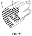
- FIG. 6 illustrates a more complexly shaped air sleeve end 50 which may also benefit from being formed using the above disclosed inventive method.
- the end portion 52 is formed from a fiber loaded elastomer in accordance with the present invention.
- the more simply contoured sleeve ends, as illustrated in FIG 5A, may be formed using a fabric/cord reinforcement layer; while it is better to use the fiber loaded elastomer for more complexly configured sleeve ends, as illustrated in FIG. 6, to achieve the desired configuration.
Landscapes
- Engineering & Computer Science (AREA)
- General Engineering & Computer Science (AREA)
- Mechanical Engineering (AREA)
- Diaphragms And Bellows (AREA)
- Fluid-Damping Devices (AREA)
- Moulding By Coating Moulds (AREA)
Applications Claiming Priority (2)
| Application Number | Priority Date | Filing Date | Title |
|---|---|---|---|
| US09/592,247 US6264178B1 (en) | 2000-06-13 | 2000-06-13 | Molded air sleeves |
| US592247 | 2000-06-13 |
Publications (3)
| Publication Number | Publication Date |
|---|---|
| EP1164309A2 true EP1164309A2 (de) | 2001-12-19 |
| EP1164309A3 EP1164309A3 (de) | 2003-08-27 |
| EP1164309B1 EP1164309B1 (de) | 2006-04-05 |
Family
ID=24369914
Family Applications (1)
| Application Number | Title | Priority Date | Filing Date |
|---|---|---|---|
| EP01112903A Expired - Lifetime EP1164309B1 (de) | 2000-06-13 | 2001-06-05 | Geformte Luftbälge |
Country Status (5)
| Country | Link |
|---|---|
| US (1) | US6264178B1 (de) |
| EP (1) | EP1164309B1 (de) |
| JP (1) | JP2002115735A (de) |
| BR (1) | BR0102285A (de) |
| DE (1) | DE60118461T2 (de) |
Cited By (2)
| Publication number | Priority date | Publication date | Assignee | Title |
|---|---|---|---|---|
| WO2004020866A1 (en) * | 2002-08-30 | 2004-03-11 | Freudenberg-Nok General Partnership | Airspring sleeve |
| EP1548320A1 (de) * | 2003-12-22 | 2005-06-29 | Continental AG | Luftfeder |
Families Citing this family (21)
| Publication number | Priority date | Publication date | Assignee | Title |
|---|---|---|---|---|
| US6637733B1 (en) * | 2002-06-12 | 2003-10-28 | Bfs Diversified Products, Llc | Air spring with vibration isolation |
| MXPA03006214A (es) * | 2002-07-22 | 2004-02-04 | Goodyear Tire & Rubber | Compuesto que tiene compuesto de caucho con hidrotalcita. |
| US6719279B1 (en) * | 2002-08-21 | 2004-04-13 | Bfs Diversified Products, Llc | Air spring sleeve |
| US20040248485A1 (en) | 2003-06-03 | 2004-12-09 | Kerstetter Randal Howard | Airsleeve |
| US7250203B2 (en) * | 2003-10-16 | 2007-07-31 | The Goodyear Tire & Rubber Company | Airsleeve |
| DE102004016660B3 (de) * | 2004-04-05 | 2005-12-01 | Contitech Luftfedersysteme Gmbh | Luftfederrollbalg aus elastomerem Werkstoff |
| US20060071378A1 (en) * | 2004-10-05 | 2006-04-06 | Bfs Diversified Products, Llc | Fluid suspension apparatus and method of manufacturing same |
| US20060131797A1 (en) | 2004-12-22 | 2006-06-22 | Kerstetter Randal H Iii | Airspring |
| US7703480B1 (en) * | 2005-08-01 | 2010-04-27 | Hillerich & Bradsby Co. | Composite tubes and method of manufacturing same |
| DE102005041800B3 (de) * | 2005-09-02 | 2007-03-01 | Otto Sauer Achsenfabrik Gmbh | Luftfederbalg |
| DE102006033197A1 (de) * | 2006-07-18 | 2008-01-24 | Continental Aktiengesellschaft | Rollbalg für eine Luftfeder |
| US8800974B2 (en) | 2006-11-14 | 2014-08-12 | Firestone Industrial Products Company, Llc | Air spring sleeve |
| EP2031267B1 (de) * | 2007-08-30 | 2012-12-26 | BFS Diversified Products, LLC. | Gasfederanordnung und Herstellungsverfahren |
| WO2009032580A2 (en) * | 2007-08-31 | 2009-03-12 | Firestone Industrial Products Company, Llc | Spring body for gas spring assembly and method of forming same |
| CN102187114A (zh) | 2008-08-14 | 2011-09-14 | 凡士通工业产品公司 | 进行重复变形的橡胶制品和制造其的组合物 |
| DE102010000290A1 (de) * | 2010-02-03 | 2011-08-04 | ContiTech Luftfedersysteme GmbH, 30165 | Luftfedereinrichtung eines Schienenfahrzeuges |
| DE102010061163B4 (de) * | 2010-12-10 | 2019-04-11 | Contitech Luftfedersysteme Gmbh | Luftfeder für Nutzfahrzeuge mit einem Rollbalg aus elastomerem Werkstoff, dessen Enden jeweils einen Befestigungswulst aufweisen |
| FR2973089B1 (fr) * | 2011-03-24 | 2013-04-19 | Hutchinson | Membrane pour suspension secondaire a air de vehicule terrestre ou ferroviaire, son procede de fabrication, suspension et vehicule l'incorporant. |
| JP6274940B2 (ja) * | 2014-03-26 | 2018-02-07 | キーパー株式会社 | 配線用ダストカバー及び配線用ダストカバー組み付け方法 |
| CN110953283A (zh) * | 2019-08-07 | 2020-04-03 | 安徽莱特气弹簧有限公司 | 一种控阀活塞及其生产加工方法和气弹簧 |
| KR102212684B1 (ko) * | 2020-07-30 | 2021-02-04 | 현대자동차주식회사 | 에어 스프링 |
Family Cites Families (15)
| Publication number | Priority date | Publication date | Assignee | Title |
|---|---|---|---|---|
| US2922637A (en) | 1957-05-29 | 1960-01-26 | Gen Motors Corp | Air spring bellows |
| NL129255C (de) * | 1964-03-11 | Michelin & Cie | ||
| US3794538A (en) | 1970-07-13 | 1974-02-26 | Goodyear Tire & Rubber | Method of making a rolling lobe diaphragm |
| US4673168A (en) | 1985-06-25 | 1987-06-16 | The Goodyear Tire & Rubber Company | Airspring and a method for making airspring flexible members |
| JPS62292939A (ja) * | 1986-06-13 | 1987-12-19 | Bridgestone Corp | 空気ばね |
| US4844429A (en) | 1986-11-10 | 1989-07-04 | The Firestone Tire & Rubber Company | Die spring construction |
| US4763883A (en) | 1987-03-30 | 1988-08-16 | The Gates Rubber Company | Airspring and sleeve |
| US4762308A (en) | 1987-03-30 | 1988-08-09 | The Firestone Tire & Rubber Company | Damping valve for air spring suspension systems |
| US4784376A (en) | 1987-06-17 | 1988-11-15 | The Firestone Tire & Rubber Company | End cap assembly for air spring |
| US5201499A (en) | 1991-08-28 | 1993-04-13 | Bridgestone/Firestone, Inc. | Fabric reinforced stiffener for air springs |
| DE4342888C1 (de) * | 1993-12-16 | 1995-04-06 | Continental Ag | Luftfeder mit einem abgedichtet befestigten Luftfederbalg |
| DE4423601C2 (de) | 1994-07-06 | 1997-08-21 | Continental Ag | Luftfederrollbalg aus elastomerem Werkstoff |
| DE4423602A1 (de) * | 1994-07-06 | 1996-01-11 | Continental Ag | Verfahren zur Herstellung von wulstlosen Schlauchrollbälgen |
| US5580033A (en) | 1995-04-07 | 1996-12-03 | The Goodyear Tire & Rubber Company | Bellows type air spring and method of making same |
| DE29619081U1 (de) | 1996-11-04 | 1997-01-09 | ContiTech Luftfedersysteme GmbH, 30165 Hannover | Rollbalg-Luftfeder |
-
2000
- 2000-06-13 US US09/592,247 patent/US6264178B1/en not_active Expired - Fee Related
-
2001
- 2001-06-05 DE DE60118461T patent/DE60118461T2/de not_active Expired - Fee Related
- 2001-06-05 EP EP01112903A patent/EP1164309B1/de not_active Expired - Lifetime
- 2001-06-06 BR BR0102285-7A patent/BR0102285A/pt not_active IP Right Cessation
- 2001-06-08 JP JP2001173804A patent/JP2002115735A/ja active Pending
Cited By (3)
| Publication number | Priority date | Publication date | Assignee | Title |
|---|---|---|---|---|
| WO2004020866A1 (en) * | 2002-08-30 | 2004-03-11 | Freudenberg-Nok General Partnership | Airspring sleeve |
| US7588234B2 (en) | 2002-08-30 | 2009-09-15 | Freudenberg-Nok General Partnership | Airspring sleeve |
| EP1548320A1 (de) * | 2003-12-22 | 2005-06-29 | Continental AG | Luftfeder |
Also Published As
| Publication number | Publication date |
|---|---|
| BR0102285A (pt) | 2002-02-19 |
| EP1164309B1 (de) | 2006-04-05 |
| DE60118461D1 (de) | 2006-05-18 |
| US6264178B1 (en) | 2001-07-24 |
| JP2002115735A (ja) | 2002-04-19 |
| EP1164309A3 (de) | 2003-08-27 |
| DE60118461T2 (de) | 2006-11-02 |
Similar Documents
| Publication | Publication Date | Title |
|---|---|---|
| US6264178B1 (en) | Molded air sleeves | |
| US5580033A (en) | Bellows type air spring and method of making same | |
| US4741517A (en) | Air spring with extensible fabric restraining cylinder | |
| US3897941A (en) | Reinforced fluid spring | |
| EP1530690B1 (de) | Luftfederbalg | |
| US4787608A (en) | Nylon bead reinforcement ring for fluid pressure devices | |
| AU645436B2 (en) | Fabric reinforced stiffener for air springs | |
| US9587700B2 (en) | Roll-off piston for an air spring rolling-lobe flexible member | |
| JPH0718464B2 (ja) | 空気ばね | |
| CN115210090B (zh) | 端构件组件以及包括该端构件组件的气弹簧组件 | |
| US20210061038A1 (en) | Air spring bellows for air suspension systems | |
| US6460586B1 (en) | Multi-region band element for run flat tire | |
| KR101100634B1 (ko) | 공기 타이어 | |
| US6363986B1 (en) | Band element and method for building same for a run flat banded tire | |
| US7784771B2 (en) | Spring body for gas spring assembly and method of forming same | |
| CA2227705A1 (en) | Abrasion-resistant elastomeric member of a tire-building drum | |
| EP3825148B1 (de) | Verfahren zur herstellung eines nicht-pneumatischen reifens und nicht-pneumatischer reifen | |
| US6676788B1 (en) | Tire building bladder | |
| JPH0379401A (ja) | 空気入りタイヤ | |
| EP1177091B1 (de) | Balg zur reifenformgebung | |
| KR20240146556A (ko) | Y-형상 스포크 구조를 갖는 비공압 타이어 | |
| CN121241210A (zh) | 带有内部回弹限制组件的气弹簧组件和包括该气弹簧组件的悬架系统 | |
| JPH11153174A (ja) | ダストカバー付きバンパーラバー | |
| JPH04111933U (ja) | 筒形防振ゴム | |
| JPH06270292A (ja) | 流体圧力装置用フレキシブルスリーブの製造方法 |
Legal Events
| Date | Code | Title | Description |
|---|---|---|---|
| PUAI | Public reference made under article 153(3) epc to a published international application that has entered the european phase |
Free format text: ORIGINAL CODE: 0009012 |
|
| AK | Designated contracting states |
Kind code of ref document: A2 Designated state(s): AT BE CH CY DE DK ES FI FR GB GR IE IT LI LU MC NL PT SE TR |
|
| AX | Request for extension of the european patent |
Free format text: AL;LT;LV;MK;RO;SI |
|
| PUAL | Search report despatched |
Free format text: ORIGINAL CODE: 0009013 |
|
| AK | Designated contracting states |
Designated state(s): AT BE CH CY DE DK ES FI FR GB GR IE IT LI LU MC NL PT SE TR |
|
| AX | Request for extension of the european patent |
Extension state: AL LT LV MK RO SI |
|
| 17P | Request for examination filed |
Effective date: 20040227 |
|
| AKX | Designation fees paid |
Designated state(s): DE FR GB |
|
| 17Q | First examination report despatched |
Effective date: 20050203 |
|
| GRAP | Despatch of communication of intention to grant a patent |
Free format text: ORIGINAL CODE: EPIDOSNIGR1 |
|
| GRAS | Grant fee paid |
Free format text: ORIGINAL CODE: EPIDOSNIGR3 |
|
| GRAA | (expected) grant |
Free format text: ORIGINAL CODE: 0009210 |
|
| AK | Designated contracting states |
Kind code of ref document: B1 Designated state(s): DE FR GB |
|
| REG | Reference to a national code |
Ref country code: GB Ref legal event code: FG4D |
|
| REF | Corresponds to: |
Ref document number: 60118461 Country of ref document: DE Date of ref document: 20060518 Kind code of ref document: P |
|
| PGFP | Annual fee paid to national office [announced via postgrant information from national office to epo] |
Ref country code: GB Payment date: 20060524 Year of fee payment: 6 |
|
| ET | Fr: translation filed | ||
| PLBE | No opposition filed within time limit |
Free format text: ORIGINAL CODE: 0009261 |
|
| STAA | Information on the status of an ep patent application or granted ep patent |
Free format text: STATUS: NO OPPOSITION FILED WITHIN TIME LIMIT |
|
| 26N | No opposition filed |
Effective date: 20070108 |
|
| PGFP | Annual fee paid to national office [announced via postgrant information from national office to epo] |
Ref country code: DE Payment date: 20070629 Year of fee payment: 7 |
|
| GBPC | Gb: european patent ceased through non-payment of renewal fee |
Effective date: 20070605 |
|
| PGFP | Annual fee paid to national office [announced via postgrant information from national office to epo] |
Ref country code: FR Payment date: 20070605 Year of fee payment: 7 |
|
| PG25 | Lapsed in a contracting state [announced via postgrant information from national office to epo] |
Ref country code: GB Free format text: LAPSE BECAUSE OF NON-PAYMENT OF DUE FEES Effective date: 20070605 |
|
| REG | Reference to a national code |
Ref country code: FR Ref legal event code: ST Effective date: 20090228 |
|
| PG25 | Lapsed in a contracting state [announced via postgrant information from national office to epo] |
Ref country code: DE Free format text: LAPSE BECAUSE OF NON-PAYMENT OF DUE FEES Effective date: 20090101 |
|
| PG25 | Lapsed in a contracting state [announced via postgrant information from national office to epo] |
Ref country code: FR Free format text: LAPSE BECAUSE OF NON-PAYMENT OF DUE FEES Effective date: 20080630 |