EP1164715A2 - Verfahren zur Sendeleistungssteuerung für einem Funkkommunikationsgerät - Google Patents
Verfahren zur Sendeleistungssteuerung für einem Funkkommunikationsgerät Download PDFInfo
- Publication number
- EP1164715A2 EP1164715A2 EP01114273A EP01114273A EP1164715A2 EP 1164715 A2 EP1164715 A2 EP 1164715A2 EP 01114273 A EP01114273 A EP 01114273A EP 01114273 A EP01114273 A EP 01114273A EP 1164715 A2 EP1164715 A2 EP 1164715A2
- Authority
- EP
- European Patent Office
- Prior art keywords
- control
- transmission power
- controlling
- variable power
- station
- Prior art date
- Legal status (The legal status is an assumption and is not a legal conclusion. Google has not performed a legal analysis and makes no representation as to the accuracy of the status listed.)
- Withdrawn
Links
Images


Classifications
-
- H—ELECTRICITY
- H04—ELECTRIC COMMUNICATION TECHNIQUE
- H04W—WIRELESS COMMUNICATION NETWORKS
- H04W52/00—Power management, e.g. Transmission Power Control [TPC] or power classes
- H04W52/04—Transmission power control [TPC]
- H04W52/52—Transmission power control [TPC] using AGC [Automatic Gain Control] circuits or amplifiers
-
- H—ELECTRICITY
- H04—ELECTRIC COMMUNICATION TECHNIQUE
- H04W—WIRELESS COMMUNICATION NETWORKS
- H04W52/00—Power management, e.g. Transmission Power Control [TPC] or power classes
- H04W52/04—Transmission power control [TPC]
- H04W52/30—Transmission power control [TPC] using constraints in the total amount of available transmission power
- H04W52/36—Transmission power control [TPC] using constraints in the total amount of available transmission power with a discrete range or set of values, e.g. step size, ramping or offsets
Definitions
- the present invention relates to a transmission power control method and radio communications apparatus effective for control of transmission power in the cellular CDMA (Code Division Multiple Access) system.
- CDMA Code Division Multiple Access
- a single frequency band is shared by a plurality of users. This results in the fact that a signal from another station acts as an interference wave and degrades the circuit quality of a local station.
- transmission power control is used. Particularly, As a transmission power control method for following an interference signal that varies instantaneously, a transmission power control method via closed loop is known.
- Fig. 12 shows an example of a conventional transmission power control method via closed loop.
- the base station determines a transmission power bit from a radio wave received from the mobile station (S11), inserts the transmission power control bit in a transmission signal, and transmits the resulting signal to the mobile station.
- the mobile station receives the signal transmitted from the base station, extracts the transmission power bit (S15) and controls its variable power amplification means according to the instruction of the transmission power control bit (S16).
- the mobile station determines a transmission power bit from a radio waved received from the base station (S14), inserts the transmission power control bit in the transmission signal, and transmits the resulting signal to the base station.
- the base station receives the signal transmitted from the mobile station, extracts the transmission power bit (S12) and controls its variable power amplification means according to the instruction of the transmission power control bit (S13).
- the invention in view of the problems, aims at providing a transmission power control method whereby the accuracy of transmission power control is upgraded and lower power consumption and a smaller apparatus design are allowed via a simple configuration, and radio communications apparatus that uses the control method.
- a transmission power control method is a transmission power control method for controlling the power to transmit to the distant party, characterized in that the method comprises variable power amplifying steps (S105, S205) for respectively controlling digital-to-analog conversion means provided in the preliminary stage of a modulator for frequency-converting a transmission signal to a signal in the IF band, the means generating an analog baseband signal to be supplied to the modulator, and a plurality of variable power amplification means for variably amplifying the transmission signal modulated by the modulator.
- variable power amplifying steps S105, S205
- the method comprises variable power amplifying steps (S105, S205) for respectively controlling digital-to-analog conversion means provided in the preliminary stage of a modulator for frequency-converting a transmission signal to a signal in the IF band, the means generating an analog baseband signal to be supplied to the modulator, and a plurality of variable power amplification means for variably amplifying the transmission signal modulated by the modulator.
- a transmission power control method is characterized in that the variable power amplifying steps modify the control ratio of the variable power amplification means and make series or parallel control in the control range.
- a transmission power control method is characterized in that the method comprises steps of detecting the state of a local station or a distant station (S102, S202) and steps of modifying the control ratio according to the detected state.
- a transmission power control method is characterized in that the method comprises steps of detecting a plurality of states of a local station or a distant station (S102, S202) and steps of modifying the control ratio by using the fuzzy control rules and fuzzy inference that are based on the plurality of states.
- a transmission power control method is characterized in that the method comprises a step of adaptively modifying the control ratio according to the state of a local station or a distant station.
- a transmission power control method is characterized in that the control sensitivity of each of the plurality of variable power amplification means differs from each other.
- a transmission power control method is a transmission power control method for controlling the power to transmit to the distant party, characterized in that the method comprises voltage control means controlling steps (S104, S204) for controlling a plurality of voltage control means that control a power amplifier for amplifying a transmission signal via separate bias systems.
- a transmission power control method is characterized in that the voltage control means controlling steps modify the control ratio of the voltage control means and make series or parallel control in the control range.
- a transmission power control method is characterized in that the method comprises steps of detecting the state of a local station or adistant station (S102, S202) and steps of modifying the control ratio according to the detected state.
- a transmission power control method is characterized in that the method comprises steps of detecting a plurality of states of a local station or a distant station (S102, S202) and steps of modifying the control ratio by using the fuzzy control rules and fuzzy inference that are based on the plurality of states.
- a transmission power control method is characterized in that the method comprises a step of adaptively modifying the control ratio according to the state of a local station or a distant station.
- a transmission power control method is characterized in that the control sensitivity of each of the plurality of variable power amplification means differs with each other.
- Radio communications apparatus is radio communications apparatus equipped with the transmission power control feature for controlling the power to be transmitted to the distant station, characterized in that the apparatus comprises variable power amplification means including a digital-to-analog conversion means (DAC 17) provided in the preliminary stage of a modulator (modulator 16) for frequency-converting a transmission signal to a signal in the IF band, the means generating an analogbaseband signal to be supplied to the modulator and a plurality of variable power amplifiers (variable amplifiers 14, 15) for variably amplifying the transmission signal modulated by the modulator, and variable power amplification control means (variable power amplification control means 18) for controlling the variable power amplification means.
- DAC 17 digital-to-analog conversion means
- Radio communications apparatus is characterized in that the variable power amplification control means modifies the control ratio of the variable power amplifier and make series or parallel control in the control range.
- Radio communications apparatus is characterized in that the apparatus has state detection means (state detection means 23) for detecting the state of a local station or a distant station and modifies the control ratio according to the detected state.
- state detection means 23 for detecting the state of a local station or a distant station and modifies the control ratio according to the detected state.
- Radio communications apparatus is characterized in that the apparatus modifies the control ratio based on the fuzzy control rules and fuzzy inference.
- Radio communications apparatus is characterized in that the apparatus adaptively modifies the control ratio according to the state of a local station or a distant station.
- Radio communications apparatus is characterized in that the control sensitivity of each of the plurality of variable power amplification means differs from each other.
- Radio communications apparatus is radio communications apparatus equipped with the transmission power control feature for controlling the power to be transmitted to the distant station, characterized in that the apparatus comprises a power amplifier (power amplifier 13) for amplifying a transmission signal, a plurality of voltage control means (first and second voltage control means 19, 20) for controlling the power amplifier via separate bias systems, and control means for controlling voltage control means (control means for controlling voltage control means 21) that controls the voltage control means.
- a power amplifier power amplifier 13
- first and second voltage control means 19, 20 for controlling the power amplifier via separate bias systems
- control means for controlling voltage control means control means for controlling voltage control means 21
- Radio communications apparatus is characterized in that the control means for controlling voltage control means modifies the control ratio of the voltage control means and make series or parallel control in the control range.
- Radio communications apparatus is characterized in that the apparatus has state detection means (state detection means 23) for detecting the state of a local station or a distant station and modifies the control ratio according to the detected state.
- state detection means 23 for detecting the state of a local station or a distant station and modifies the control ratio according to the detected state.
- Radio communications apparatus is characterized in that the apparatus modifies the control ratio based on the fuzzy control rules and fuzzy inference.
- Radio communications apparatus is characterized in that the apparatus adaptively modifies the control ratio according to the state of a local station or a distant station.
- Radio communications apparatus is characterized in that the control sensitivity of each of the plurality of variable power amplification means differs from each other.
- the means via a configuration for respectively controlling digital-to-analog conversion means provided in the preliminary stage of a modulator for frequency-converting a transmission signal to a signal in the IF band, the means generating an analog baseband signal to be supplied to the modulator, and a plurality of variable power amplification means for variably amplifying the transmission signal modulated by the modulator, it is possible to upgrade the accuracy of transmit power control and assure lower power consumption and smaller size of apparatus via a simple configuration
- Fig. 1 is a flowchart showing the procedure of the transmission power control method according to first embodiment of the invention.
- the base station determines a transmission power bit from a radio wave received from the mobile station (S101), inserts the transmission power control bit in a transmission signal, and transmits the resulting signal to the mobile station.
- the mobile station receives the signal transmitted from the base station, extracts the transmission power bit (S203) and controls its variable power amplification unit according to the transmission power control bit and the states of the local station and the distant station detected in Step 202 (S205).
- the mobile station can modify the control ratio of the variable power amplification unit according to the states of the local station and the distant station.
- the mobile station detects the absolute value of transmission power of the local station in Step 202 and increases the control ratio of a former stage variable power amplification unit constituting the variable power amplification unit in proportion to the absolute value of transmission power of the local station in Step S205.
- the variable power amplification unit is an active element
- This approach improves the carrier-to-noise ratio (C/N) over the related art case where the control ratio is fixed.
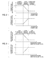
- Fig. 2 shows an example of controlling the variable power amplification unit (case 1).
- the transmission power is represented as P[dBm], the transmission power control volume as PC[dB], the control ratio of the former variable power amplifier (former stage GCA) as K1, the control volume of the former stage variable power amplifier (former stage GCA)in PC1 [dB], the control ratio of the subsequent stage variable power amplifier (subsequent stage GCA) as K2 and the control volume of the subsequent stage variable power amplifier (subsequent stage GCA) as PC2[dB].
- the control ratio of the former stage GCAK1 is increased when the absolute value of transmission power P is small and the control ratio of the subsequent stage GCA K2 is increased when the absolute value of transmission power P is large (series control).
- the intermediate control area where control via the former stage GCA is switched over to control via the subsequent stage GCA (parallel control)
- continuous switchover of control is made possible by arranging so that the sum of the control ratios of the former stage GCA and the subsequent stage GCA may be equal to 1.
- Step 202 the variation volume and the variation velocity of the transmission power of the local station are detected.
- Step 205 the greater the variation volume is and the higher the variation velocity of the transmission power of the local station is, the control ratio of the variable power amplifier that has the higher control sensitivity is increased.
- Step 205 in case sudden control of the transmission power in the mobile station is desired, the mobile station increases the control ratio of the variable power amplifier that has the higher control sensitivity, and in case gradual control of the transmission power in the mobile station is desired, the mobile station increases the control ratio of the variable power amplifier that has the lower control sensitivity.
- the variable power amplifier that has the higher control sensitivity provides large control volume and high follow-up ability and the variable power amplifier that has the lower control sensitivity provides small control volume and high control accuracy.
- Step S202 the mobile station detects the variation volume and the variation velocity of the transmission power of the local station based on the variation volume and the variation velocity of the received power, transmission power and transmission power control bit of the distant station.
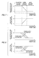
- Fig. 3 shows an example of controlling variable power amplification unit (case 2).
- the transmission power variation volume is represented as PD[dB], the transmission power control volume as PC[dB], the control ratio of a variable power amplifier that has the higher control sensitivity (high-sensitivity GCA) as K1, the control volume of the variable power amplifier that has the higher control sensitivity (high-sensitivity GCA) as PC1[dB], the control ratio of a variable power amplifier that has the lower control sensitivity (low-sensitivity GCA) as K2, and the control volume of the variable power amplifier that has the lower control sensitivity (low-sensitivity GCA) as PC2 [dB].
- the control ratio of the low-sensitivity GCA K2 is increased when the transmission power variation volume PD is small and the control ratio of the high-sensitivity GCA K1 is increased when the transmission power variation volume PD is large (series control) .
- the intermediate control area where control via the lower-sensitivity GCA is switched over to control via the higher-sensitivity GCA (parallel control)
- continuous switchover of control is made possible by arranging so that the sum of the control ratios of the preliminary GCA and the secondary GCA may be equal to 1.
- variable power amplification unit may be controlled based on the transmission power variation volume and the transmission power variation velocity.
- the transmission power variation velocity is represented as PV[dB/s].
- the control ratio of the high-sensitivity GCA K1 is increased when the transmission power variation velocity PV is higher, and the control ratio of the lower-sensitivity GCA K2 is increased when the transmission power variation velocity PV is lower.
- the mobile station may use the fuzzy inference that is based on the variation volume and variation velocity of the transmission power of the local station to determine the control ratio. Via this approach, it is possible to properly determine the control ratio and upgrade the transmission power control accuracy.
- Fig. 5 shows an example of controlling the variable power amplification unit via fuzzy inference (case 4).
- the transmission power variation volume is represented as PD[dB], the transmission power variation velocity as PV[dB], the transmission power control volume as PC[dB], the control amount of the variable power amplifier that has the higher control sensitivity (high-sensitivity GCA) as PC1[dB], and the control volume of the variable power amplifier that has the lower control sensitivity (low-sensitivity GCA) as PC2[dB].
- Fuzzy control rules and fuzzy inference are implemented via the minimax barycenter method. That is, the membership values ⁇ PDi (PD) and ⁇ PVi (PV) of the current transmission power variation volume PD and the transmission power variation velocity PV are calculated from Figs.
- K* ⁇ K ⁇ Ki*(K)dK/ ⁇ Ki*(K)dK
- Step S205 the mobile station adaptively modifies the control ratio of the variable power amplification unit according to the states of the local station and the distant station detected in Step 202.
- the mobile station can adaptively correct the control ratio of the variable power amplification unit according to the temperature of the local station, power-supply voltage, transmission frequency, diffusion ratio of a transmission signal, code multiplicity of a transmission signal, and peak value of the transmission signal.
- the output accuracy of the transmission power is upgraded compared with a case where the control ratio is not corrected as in related art applications, thereby upgrading the transmission power control accuracy.
- the mobile station can adaptively correct the transmission power according to environmental changes. Accordingly, it is possible to correct the transmission power according to the environmental changes without modifying apparatus for a new factor of environmental changes. This leads to a simplified apparatus design and lower power consumption.
- the coefficient of a digital filter provided in the preliminary stage of the digital-to-analog converter (DAC) for generating these signals is modified.
- Step S205 the mobile station controls a plurality of variable power amplifiers having different control sensitivities.
- the mobile station can set the control ratios of the variable power amplifiers having different control sensitivities to proper values in order to upgrade the linearity of the control characteristics, thus upgrading the transmission power control accuracy.
- Fig. 6 shows an example of controlling variable power amplification unit (case 5).
- the output power is represented as P, the control sensitivity as ⁇ P, the control voltage as VGC, the output power of the first variable power amplifier as P1, the control sensitivity of the first variable power amplifier as ⁇ P1, the output power of the second variable power amplifier as P2, and the control sensitivity of the second variable power amplifier as ⁇ P2.
- the output power P1 has a substantially linear characteristic except where the control voltage VGC falls within the range of 1 to 2[V].
- the control characteristics of the second variable power amplifier Fig.
- the output power P2 has a substantially linear characteristic where the control voltage VGC falls within the range of 1 to 2[V].
- the first variable power amplifier where the control voltage is below 1[V] and above 2[V]
- selecting the second variable power amplifier where the control voltage is within the range of 1[V] to 2[V]
- a linear characteristic is obtained via the first and the second variable power amplifiers (Fig. 6C).
- the mobile station inserts the transmission power control bit determined in Step 201 in a transmission signal and transmits the resulting signal to the base station.
- the base station receives the signal transmitted from the mobile station, extracts the transmission power bit (S103) and controls its variable power amplification unit according to the states of the local station and the distant station detected in Step S102 (S105). Processing in Steps S102, S105 is the same as that in Steps in S202, S205, thus upgrading the transmission power control accuracy and allowing a simplified apparatus design and lower power consumption.
- Fig. 1 is a flowchart showing the procedure of the transmission power control method according to second embodiment of the invention.
- the base station determines a transmission power bit from a radio wave received from themobile station (S101), inserts the transmission power control bit in a transmission signal, and transmits the resulting signal to the mobile station.
- the mobile station receives the signal transmitted from the base station, extracts the transmission power bit (S203) and controls its variable power amplification unit according to the transmission power control bit and the states of the local station and the distant station detected in Step 202 (S204).
- the mobile station can modify the control ratio of voltage control unit according to the states of the local station and the distant station. For example, the mobile station detects the absolute value and the power-supply voltage of transmission power of the local station in Step 202. The mobile station increases the control ratio of voltage control unit for correcting the collector voltage of the power amplifier in proportion to the absolute value of transmission power of the local station and the power-supply voltage in Step 204. This enhances the efficiency and stability of the power amplifier, thus reducing the power consumption and upgrading the transmission power control accuracy, compared with a case where the control ratio is fixed as in related art applications. In case bias control is made on the power amplifier, the collector voltage or base voltage is controlled for reducing a consumption current.
- bias control is dedicated to control of the collector voltage or base voltage
- variation in the transmission power or power-supply voltage invites various characteristics such as increased co-channel leak power, lower stability and reduced gain.
- fixing the bias voltage results in a noticeable difference between characteristics at the upper limit and the lower limit of the transmission power.
- Fig. 7 shows an example of a controlling voltage control unit (case 1).
- the transmission power is represented as P[dB], the voltage control volume as VC[dB], a control ratio of a voltage controller for controlling the collector voltage as K1, a control volume of the voltage controller for controlling a collector voltage as VC1[dB], a control ratio of a voltage controller for controlling the base voltage as K2, and the control volume of a voltage controller for controlling a base voltage as VC2[dB].
- the control ratio of the voltage controller for controlling the collector voltage is increased when the absolute value of transmission power is small and the control ratio of the voltage controller for controlling the base voltage is increased when the absolute value of transmission power is large (series control).
- the intermediate control area where collector voltage control is switched over to base voltage control parallel control
- continuous switchover of control is made possible by arranging so that the sum of the control ratios of collector voltage control and base voltage control may be equal to 1.
- the collector voltage is generated by a DC/DC converter.
- Fig. 7 shows a control example where the usage ratio of the converter can be reduced when the consumption current is larger.
- the voltage control unit may be controlled based on the absolute value of transmission power and the power-supply voltage.
- the power-supply voltage is represented as V[V].
- the control ratio of the voltage controller for controlling the collector voltage is increased when the power-supply voltage is higher and the control ratio of the voltage controller for controlling the base voltage is increased when the power-supply voltage is smaller.
- Fig. 8 shows a control example where the collector voltage can be increased.
- the mobile station may determine the control ratio by using fuzzy inference that is based on the absolute value of transmission power and the power-supply voltage of the local station detected in Step S202. Via this approach, it is possible to properly determine the control ratio, thus reducing the power consumption and upgrading the transmission power control accuracy.
- Figs . 9A-9C shows an example of controlling voltage control unit (case 3).
- the transmission power is represented as P[dB], the power-supply voltage as V[V], the voltage control volume as VC[dB], the control ratio of the voltage controller for controlling the collector voltage as K1, the control volume of the voltage controller for controlling the collector voltage as VC1[dB], the control ratio of the voltage controller for controlling the base voltage as K2, and the control volume of the voltage controller for controlling the base voltage as VC2[dB].
- Fuzzy control rules and fuzzy inference are implemented via the minimax barycenter method. That is, the membership values ⁇ PDi (P) and ⁇ Vi (V) of the current transmission power P and the power-supply voltage V are calculated from Figs.
- K* ⁇ K ⁇ Ki*(K)dK/ ⁇ Ki*(K)dK
- Step S204 the mobile station adaptively modifies the control ratio of the voltage control unit according to the states of the local station and the distant station detected in Step 202.
- the mobile station can adaptively correct the control ratio of the voltage control unit according to the temperature of the local station, power-supply voltage, transmission frequency, diffusion ratio of a transmission signal, code multiplicity of a transmission signal, and peak value of the transmission signal.
- the output accuracy of the transmission power is upgraded compared with a case where the control ratio is not corrected as in related art applications, thereby upgrading the transmission power control accuracy.
- the mobile station can adaptively correct the transmission power according to environmental changes. Accordingly, it is possible to correct the transmission power according to the environmental changes without modifying apparatus for a new factor of environmental changes . This leads to a simplified apparatus design and lower power consumption.
- the coefficient of a digital filter provided in the former stage of the digital-to-analog converter (DAC) for generating these signals is modified.
- Step S204 the mobile station controls a plurality of voltage controllers having different control sensitivities.
- the mobile station can set the control ratios of the voltage controllers having different control sensitivities to proper values in order to upgrade the linearity of the control characteristics, thus upgrading the transmission power control accuracy.
- Fig. 10 shows an example of controlling voltage control unit (case 4).
- the output voltage is represented as P, the control sensitivity as ⁇ P, the power-supply voltage as V, the output voltage of the first voltage controller as P1, the control sensitivity of the first voltage controller as ⁇ P1, the output voltage of the second voltage controller as P2, and the control sensitivity of the second voltage controller as ⁇ P2.
- the output voltage P1 has a substantially linear characteristic except where the power-supply voltage V falls within the range of 1 to 2[V].
- the control characteristics of the second voltage controller Fig.
- the output voltage P2 has a substantially linear characteristic where the power-supply voltage V falls within the range of 1 to 2[V].
- a linear characteristic is obtained via the first and the second voltage controllers (Fig. 10C).
- the mobile station inserts the transmission power control bit determined in Step 201 in a transmission signal and transmits the resulting signal to the base station.
- the base station receives the signal transmitted from the mobile station, extracts the transmission power bit (S103) and controls its variable power amplification unit according to the states of the local station and the distant station detected in Step S102 (S104). Processing in Steps S102, S104 is the same as that in Steps in S202, S204, thus upgrading the transmission power control accuracy and allowing a simplified apparatus design and lower power consumption.
- Fig. 11 is a block diagram showing an embodiment of radio communications apparatus according to the invention.
- the numeral 11 represents an antenna, 12 a transmit/receive separator, 13 a power amplifier, 14 a first variable power amplifier, 15 a second variable power amplifier, 16 a modulator, 17 a digital-to-analog converter (DAC), 18 variable power amplification control unit, 19 first voltage controller, 20 second voltage controller, 21 control unit for controlling voltage controllers, 11 a baseband signal processor, 23 state detection unit, 24 a demodulator, 25 a radio transmitter, and 26 a radio receiver.
- DAC digital-to-analog converter
- the baseband signal processor 22 determines a transmission power bit received from the base station and inserts the transmission power control bit in a transmission signal.
- the transmit signal is converted to an analog signal by the DAC 17, frequency-converted to a signal in the IF band by the modulator 16, converted to a signal in the RD band by the radio transmitter 25, then sent to the base station from the antenna 11 via the transmit/receive separator 12.
- the signal transmitted from the mobile station is received by the antenna 11.
- the received signal is input to the radio receiver 26 via the transmit/receive separator12.
- the radio signal is frequency-converted to a signal in the IF band by the radio receiver 26 and converted to a baseband signal by the demodulator 24.
- the baseband signal processor 22 extracts a transmission power control bit from the baseband signal output from the demodulator 24.
- the state detection unit 23 detects the states of the base station and the local station based on the variation volume and the variation velocity of the receiving power, transmission power and transmission power control bit of the base station and the local station, the variation volume and the variation velocity output from the baseband signal processor 22.
- the variable power amplification control unit 18 controls the first and the second variable power amplifiers 14, 15 and DAC 17 according to the extracted transmission power control bit and the detected states.
- the variable power amplification control unit 18 controls the first and the second variable power amplifiers 14, 15 based on the transmission power control shown in the first embodiment.
- the variable power amplification control unit 18 controls the gain of the DAC 17 to arrange the dynamic range and linearity of the baseband signal obtained before modulation.
- the control unit for controlling voltage controllers 21 controls the first and the second voltage controllers 19 and 20.
- the control unit for controlling voltage controllers 21 controls the first and the second voltage controllers 19 and, 20 based on the transmission power control shown in second embodiment.
Landscapes
- Engineering & Computer Science (AREA)
- Computer Networks & Wireless Communication (AREA)
- Signal Processing (AREA)
- Transmitters (AREA)
- Control Of Amplification And Gain Control (AREA)
- Mobile Radio Communication Systems (AREA)
Applications Claiming Priority (2)
| Application Number | Priority Date | Filing Date | Title |
|---|---|---|---|
| JP2000177029 | 2000-06-13 | ||
| JP2000177029A JP4610697B2 (ja) | 2000-06-13 | 2000-06-13 | 送信電力制御方法及び無線通信装置 |
Publications (2)
| Publication Number | Publication Date |
|---|---|
| EP1164715A2 true EP1164715A2 (de) | 2001-12-19 |
| EP1164715A3 EP1164715A3 (de) | 2003-07-23 |
Family
ID=18678679
Family Applications (1)
| Application Number | Title | Priority Date | Filing Date |
|---|---|---|---|
| EP01114273A Withdrawn EP1164715A3 (de) | 2000-06-13 | 2001-06-12 | Verfahren zur Sendeleistungssteuerung für einem Funkkommunikationsgerät |
Country Status (4)
| Country | Link |
|---|---|
| US (1) | US7310502B2 (de) |
| EP (1) | EP1164715A3 (de) |
| JP (1) | JP4610697B2 (de) |
| CN (1) | CN1224204C (de) |
Families Citing this family (21)
| Publication number | Priority date | Publication date | Assignee | Title |
|---|---|---|---|---|
| US6377784B2 (en) * | 1999-02-09 | 2002-04-23 | Tropian, Inc. | High-efficiency modulation RF amplifier |
| JP3439442B2 (ja) | 2000-08-30 | 2003-08-25 | 埼玉日本電気株式会社 | 送信出力レベル制御方式及びその方法 |
| US20070060074A1 (en) * | 2002-03-07 | 2007-03-15 | Matsushita Electric Industrial Co., Ltd. | High-efficiency modulating RF amplifier |
| US8428181B2 (en) * | 2002-12-02 | 2013-04-23 | Research In Motion Limited | Method and apparatus for optimizing transmitter power efficiency |
| US7751844B2 (en) * | 2003-09-24 | 2010-07-06 | Nec Corporation | Mobile communication system, radio base station, transmission power control method used therein, and program thereof |
| EP1564898A1 (de) * | 2004-02-13 | 2005-08-17 | Thomson Licensing S.A. | Radiosender mit reduzierter Leistungsaufnahme |
| DE602004000811T2 (de) * | 2004-02-20 | 2006-10-26 | Research In Motion Ltd., Waterloo | Verfahren und Vorrichtung für erhöhten Wirkungsgrad eines Leistungsverstärkers in Funkübertragungssystemen mit hohen Leistungsformfaktoren |
| US7333563B2 (en) | 2004-02-20 | 2008-02-19 | Research In Motion Limited | Method and apparatus for improving power amplifier efficiency in wireless communication systems having high peak to average power ratios |
| JP2005252471A (ja) * | 2004-03-02 | 2005-09-15 | Fujitsu Ltd | 無線通信装置及びその増幅回路の制御方法 |
| US8086519B2 (en) * | 2004-10-14 | 2011-12-27 | Cfph, Llc | System and method for facilitating a wireless financial transaction |
| US20060223447A1 (en) * | 2005-03-31 | 2006-10-05 | Ali Masoomzadeh-Fard | Adaptive down bias to power changes for controlling random walk |
| US8761305B2 (en) | 2006-06-14 | 2014-06-24 | Blackberry Limited | Input drive control for switcher regulated power amplifier modules |
| BRPI0702896A2 (pt) * | 2006-06-14 | 2011-03-15 | Res In Motoion Ltd | controle de acionamento de entrada para módulos de amplificador de energia regulados por comutador |
| US7907920B2 (en) | 2006-06-14 | 2011-03-15 | Research In Motion Limited | Control of switcher regulated power amplifier modules |
| GB2456647B (en) * | 2008-01-28 | 2012-09-12 | Cambridge Silicon Radio Ltd | Power-savings receiver |
| JP5245459B2 (ja) | 2008-03-04 | 2013-07-24 | 富士通株式会社 | 無線端末装置及び送信電力制御方法 |
| JP5255986B2 (ja) * | 2008-10-20 | 2013-08-07 | 株式会社日立ハイテクノロジーズ | パターンドメディアの検査方法及び検査装置 |
| WO2011161759A1 (ja) * | 2010-06-22 | 2011-12-29 | ルネサスエレクトロニクス株式会社 | 半導体装置 |
| US8620238B2 (en) | 2010-07-23 | 2013-12-31 | Blackberry Limited | Method of power amplifier switching power control using post power amplifier power detection |
| CN103605286B (zh) * | 2013-11-13 | 2016-04-20 | 沈阳大学 | 一种用于调节无线设备发射功率的模糊控制方法 |
| KR102034955B1 (ko) * | 2018-03-27 | 2019-10-21 | 경상대학교산학협력단 | 무선 통신 시스템에서 신경망 기반의 송신전력 제어 방법 및 장치 |
Citations (1)
| Publication number | Priority date | Publication date | Assignee | Title |
|---|---|---|---|---|
| WO1997040584A1 (en) | 1996-04-23 | 1997-10-30 | Bell Communications Research, Inc. | Hybrid analog/digital method and apparatus for controlling the transmission power level of a radio transceiver |
Family Cites Families (15)
| Publication number | Priority date | Publication date | Assignee | Title |
|---|---|---|---|---|
| JPS57166711A (en) * | 1981-04-07 | 1982-10-14 | Nippon Hamondo Kk | Power amplifier for musical instrument |
| JPH0198304A (ja) * | 1987-10-09 | 1989-04-17 | Furuno Electric Co Ltd | 電力増幅回路装置 |
| JP2637818B2 (ja) * | 1989-03-20 | 1997-08-06 | 富士通株式会社 | 無線装置における送信パワー制御装置 |
| JPH05122087A (ja) * | 1991-10-28 | 1993-05-18 | Toshiba Corp | 無線送信機 |
| JPH08191224A (ja) * | 1995-01-10 | 1996-07-23 | Fujitsu Ltd | 移動通信装置 |
| US5719898A (en) * | 1995-09-29 | 1998-02-17 | Golden Bridge Technology, Inc. | Fuzzy-logic spread-spectrum adaptive power control |
| JP3479405B2 (ja) * | 1996-03-29 | 2003-12-15 | アルプス電気株式会社 | 送信機の増幅回路 |
| JPH1093450A (ja) * | 1996-09-17 | 1998-04-10 | Fujitsu Ltd | 送信装置 |
| US6148220A (en) * | 1997-04-25 | 2000-11-14 | Triquint Semiconductor, Inc. | Battery life extending technique for mobile wireless applications |
| JP3171141B2 (ja) * | 1997-06-06 | 2001-05-28 | 日本電気株式会社 | 移動体通信用送信機およびその制御方法 |
| US6411825B1 (en) * | 1997-09-09 | 2002-06-25 | Samsung Electronics, Co., Ltd. | Distributed architecture for a base station transceiver subsystem |
| US6253092B1 (en) * | 1997-11-25 | 2001-06-26 | Uniden Financial, Inc. | Closed loop transmitter with DAC sensitivity adjusted to detector nonlinearity |
| JP3314724B2 (ja) * | 1998-06-02 | 2002-08-12 | 日本電気株式会社 | 電力増幅回路および電力自動制御方法 |
| JP2000031763A (ja) * | 1998-07-14 | 2000-01-28 | Fujitsu Ltd | 可変利得回路 |
| US7092686B2 (en) * | 2001-03-08 | 2006-08-15 | Siemens Communications, Inc. | Automatic transmit power control loop |
-
2000
- 2000-06-13 JP JP2000177029A patent/JP4610697B2/ja not_active Expired - Fee Related
-
2001
- 2001-06-12 EP EP01114273A patent/EP1164715A3/de not_active Withdrawn
- 2001-06-12 US US09/879,722 patent/US7310502B2/en not_active Expired - Fee Related
- 2001-06-13 CN CNB011211806A patent/CN1224204C/zh not_active Expired - Fee Related
Patent Citations (1)
| Publication number | Priority date | Publication date | Assignee | Title |
|---|---|---|---|---|
| WO1997040584A1 (en) | 1996-04-23 | 1997-10-30 | Bell Communications Research, Inc. | Hybrid analog/digital method and apparatus for controlling the transmission power level of a radio transceiver |
Also Published As
| Publication number | Publication date |
|---|---|
| JP4610697B2 (ja) | 2011-01-12 |
| JP2001358601A (ja) | 2001-12-26 |
| CN1329413A (zh) | 2002-01-02 |
| CN1224204C (zh) | 2005-10-19 |
| EP1164715A3 (de) | 2003-07-23 |
| US20020013157A1 (en) | 2002-01-31 |
| US7310502B2 (en) | 2007-12-18 |
Similar Documents
| Publication | Publication Date | Title |
|---|---|---|
| EP1164715A2 (de) | Verfahren zur Sendeleistungssteuerung für einem Funkkommunikationsgerät | |
| CA2052007C (en) | Radio telephone using received signal strength in controlling transmission power | |
| US6011980A (en) | Wireless telecommunication equipment | |
| US6532357B1 (en) | Radio communication device and transmission power control method for radio communication device | |
| US7039373B2 (en) | Wireless communication apparatus and transmission power control method thereof | |
| WO1985000258A1 (en) | Diversity signal strength indicator and site selection apparatus for using same | |
| KR20010015388A (ko) | 인접 채널 및 선택 채널 전력을 제어하기 위해 공급조정을 갖는 전력 증폭 회로 | |
| US6487419B1 (en) | Systems and methods for management of current consumption and performance in a receiver down converter of a wireless device | |
| US20040161030A1 (en) | High dynamic range low ripple RSSI for zero-IF or low-IF receivers | |
| US20050075087A1 (en) | Frequency converter, orthogonal demodulator and orthogonal modulator | |
| US6675000B1 (en) | Radio communication apparatus and transmission power control method therein | |
| US6728224B1 (en) | Portable mobile terminal and transmission unit | |
| US6529496B1 (en) | TSTD transmitter for limiting transmission power of antenna and controlling method thereof for base station in mobile communication system | |
| US6438387B1 (en) | Radio communication device and transmission power control method for radio communication device | |
| EP1103105B1 (de) | Vorrichtung und verfahren zur radiokommunikations-sendeleistungsregelung | |
| US5873046A (en) | System for communicating in analog or digital mode and mobile station employing the same | |
| JP3970177B2 (ja) | 無線通信装置 | |
| US6798845B1 (en) | Transmitter for mobile terminal with carrier leak suppressing circuit | |
| EP0795967A1 (de) | Verfahren zur Energieeinsparung in einem Funkempfänger | |
| JPH0740653B2 (ja) | 高周波出力制御回路 | |
| JPH06152288A (ja) | 電力制御装置 | |
| JPH05344016A (ja) | Fm無線受信機のパワーセーブ装置 |
Legal Events
| Date | Code | Title | Description |
|---|---|---|---|
| PUAI | Public reference made under article 153(3) epc to a published international application that has entered the european phase |
Free format text: ORIGINAL CODE: 0009012 |
|
| AK | Designated contracting states |
Kind code of ref document: A2 Designated state(s): AT BE CH CY DE DK ES FI FR GB GR IE IT LI LU MC NL PT SE TR |
|
| AX | Request for extension of the european patent |
Free format text: AL;LT;LV;MK;RO;SI |
|
| PUAL | Search report despatched |
Free format text: ORIGINAL CODE: 0009013 |
|
| AK | Designated contracting states |
Designated state(s): AT BE CH CY DE DK ES FI FR GB GR IE IT LI LU MC NL PT SE TR |
|
| AX | Request for extension of the european patent |
Extension state: AL LT LV MK RO SI |
|
| RIC1 | Information provided on ipc code assigned before grant |
Ipc: 7H 03G 3/30 B Ipc: 7H 04B 7/005 A |
|
| 17P | Request for examination filed |
Effective date: 20031031 |
|
| AKX | Designation fees paid |
Designated state(s): DE FR GB IT NL |
|
| RAP1 | Party data changed (applicant data changed or rights of an application transferred) |
Owner name: PANASONIC CORPORATION |
|
| 17Q | First examination report despatched |
Effective date: 20081114 |
|
| STAA | Information on the status of an ep patent application or granted ep patent |
Free format text: STATUS: THE APPLICATION IS DEEMED TO BE WITHDRAWN |
|
| 18D | Application deemed to be withdrawn |
Effective date: 20130104 |