EP1165960B1 - Soupape d'injection de carburant - Google Patents
Soupape d'injection de carburant Download PDFInfo
- Publication number
- EP1165960B1 EP1165960B1 EP01913566A EP01913566A EP1165960B1 EP 1165960 B1 EP1165960 B1 EP 1165960B1 EP 01913566 A EP01913566 A EP 01913566A EP 01913566 A EP01913566 A EP 01913566A EP 1165960 B1 EP1165960 B1 EP 1165960B1
- Authority
- EP
- European Patent Office
- Prior art keywords
- fuel injection
- injection valve
- armature
- magnet coil
- magnetic
- Prior art date
- Legal status (The legal status is an assumption and is not a legal conclusion. Google has not performed a legal analysis and makes no representation as to the accuracy of the status listed.)
- Expired - Lifetime
Links
- 239000000446 fuel Substances 0.000 claims abstract description 67
- 238000002347 injection Methods 0.000 claims abstract description 59
- 239000007924 injection Substances 0.000 claims abstract description 59
- 238000002485 combustion reaction Methods 0.000 claims abstract description 7
- 238000009792 diffusion process Methods 0.000 description 6
- 230000000694 effects Effects 0.000 description 5
- 238000010586 diagram Methods 0.000 description 4
- 239000000463 material Substances 0.000 description 4
- 230000008901 benefit Effects 0.000 description 3
- 238000002360 preparation method Methods 0.000 description 3
- 238000007789 sealing Methods 0.000 description 3
- 230000007423 decrease Effects 0.000 description 2
- 230000004907 flux Effects 0.000 description 2
- 238000004519 manufacturing process Methods 0.000 description 2
- 238000000034 method Methods 0.000 description 2
- 230000008569 process Effects 0.000 description 2
- 230000009467 reduction Effects 0.000 description 2
- 239000013585 weight reducing agent Substances 0.000 description 2
- 238000004804 winding Methods 0.000 description 2
- 239000000853 adhesive Substances 0.000 description 1
- 230000001070 adhesive effect Effects 0.000 description 1
- 230000015556 catabolic process Effects 0.000 description 1
- 238000007906 compression Methods 0.000 description 1
- 238000010276 construction Methods 0.000 description 1
- 238000006731 degradation reaction Methods 0.000 description 1
- 230000001934 delay Effects 0.000 description 1
- 230000001419 dependent effect Effects 0.000 description 1
- 230000003828 downregulation Effects 0.000 description 1
- 230000005284 excitation Effects 0.000 description 1
- 238000005457 optimization Methods 0.000 description 1
- 230000008092 positive effect Effects 0.000 description 1
- 230000002035 prolonged effect Effects 0.000 description 1
- 230000002441 reversible effect Effects 0.000 description 1
- 238000004904 shortening Methods 0.000 description 1
- 230000003313 weakening effect Effects 0.000 description 1
Images



Classifications
-
- F—MECHANICAL ENGINEERING; LIGHTING; HEATING; WEAPONS; BLASTING
- F02—COMBUSTION ENGINES; HOT-GAS OR COMBUSTION-PRODUCT ENGINE PLANTS
- F02M—SUPPLYING COMBUSTION ENGINES IN GENERAL WITH COMBUSTIBLE MIXTURES OR CONSTITUENTS THEREOF
- F02M51/00—Fuel-injection apparatus characterised by being operated electrically
- F02M51/06—Injectors peculiar thereto with means directly operating the valve needle
- F02M51/061—Injectors peculiar thereto with means directly operating the valve needle using electromagnetic operating means
- F02M51/0614—Injectors peculiar thereto with means directly operating the valve needle using electromagnetic operating means characterised by arrangement of electromagnets or fixed armature
- F02M51/0617—Injectors peculiar thereto with means directly operating the valve needle using electromagnetic operating means characterised by arrangement of electromagnets or fixed armature having two or more electromagnets
-
- F—MECHANICAL ENGINEERING; LIGHTING; HEATING; WEAPONS; BLASTING
- F01—MACHINES OR ENGINES IN GENERAL; ENGINE PLANTS IN GENERAL; STEAM ENGINES
- F01L—CYCLICALLY OPERATING VALVES FOR MACHINES OR ENGINES
- F01L9/00—Valve-gear or valve arrangements actuated non-mechanically
- F01L9/20—Valve-gear or valve arrangements actuated non-mechanically by electric means
-
- F—MECHANICAL ENGINEERING; LIGHTING; HEATING; WEAPONS; BLASTING
- F02—COMBUSTION ENGINES; HOT-GAS OR COMBUSTION-PRODUCT ENGINE PLANTS
- F02D—CONTROLLING COMBUSTION ENGINES
- F02D41/00—Electrical control of supply of combustible mixture or its constituents
- F02D41/20—Output circuits, e.g. for controlling currents in command coils
-
- F—MECHANICAL ENGINEERING; LIGHTING; HEATING; WEAPONS; BLASTING
- F02—COMBUSTION ENGINES; HOT-GAS OR COMBUSTION-PRODUCT ENGINE PLANTS
- F02M—SUPPLYING COMBUSTION ENGINES IN GENERAL WITH COMBUSTIBLE MIXTURES OR CONSTITUENTS THEREOF
- F02M51/00—Fuel-injection apparatus characterised by being operated electrically
- F02M51/06—Injectors peculiar thereto with means directly operating the valve needle
- F02M51/061—Injectors peculiar thereto with means directly operating the valve needle using electromagnetic operating means
- F02M51/0625—Injectors peculiar thereto with means directly operating the valve needle using electromagnetic operating means characterised by arrangement of mobile armatures
- F02M51/0664—Injectors peculiar thereto with means directly operating the valve needle using electromagnetic operating means characterised by arrangement of mobile armatures having a cylindrically or partly cylindrically shaped armature, e.g. entering the winding; having a plate-shaped or undulated armature entering the winding
- F02M51/0671—Injectors peculiar thereto with means directly operating the valve needle using electromagnetic operating means characterised by arrangement of mobile armatures having a cylindrically or partly cylindrically shaped armature, e.g. entering the winding; having a plate-shaped or undulated armature entering the winding the armature having an elongated valve body attached thereto
-
- F—MECHANICAL ENGINEERING; LIGHTING; HEATING; WEAPONS; BLASTING
- F02—COMBUSTION ENGINES; HOT-GAS OR COMBUSTION-PRODUCT ENGINE PLANTS
- F02D—CONTROLLING COMBUSTION ENGINES
- F02D41/00—Electrical control of supply of combustible mixture or its constituents
- F02D41/20—Output circuits, e.g. for controlling currents in command coils
- F02D2041/2068—Output circuits, e.g. for controlling currents in command coils characterised by the circuit design or special circuit elements
- F02D2041/2079—Output circuits, e.g. for controlling currents in command coils characterised by the circuit design or special circuit elements the circuit having several coils acting on the same anchor
-
- H—ELECTRICITY
- H01—ELECTRIC ELEMENTS
- H01F—MAGNETS; INDUCTANCES; TRANSFORMERS; SELECTION OF MATERIALS FOR THEIR MAGNETIC PROPERTIES
- H01F7/00—Magnets
- H01F7/06—Electromagnets; Actuators including electromagnets
- H01F7/08—Electromagnets; Actuators including electromagnets with armatures
- H01F7/16—Rectilinearly-movable armatures
- H01F2007/1676—Means for avoiding or reducing eddy currents in the magnetic circuit, e.g. radial slots
Definitions
- the invention relates to a fuel injection valve according to the preamble of claim 1.
- Another possibility is to build up a magnetic field for opening the fuel injection valve and a second magnetic field for holding the fuel injection valve in its open position.
- the strength of the holding field can then be chosen so small that the Eddy currents are small after switching off the holding field and thus the closing time can be shortened.
- an electromagnetically operable fuel injector for injecting fuel into an internal combustion engine in which the solenoid has three windings which are driven by three separate circuits.
- the first circuit for rapidly opening the fuel injection valve, the second circuit for keeping open the fuel injection valve and the third circuit for generating a magnetic field canceling the residual field for fast closing of the fuel injection valve is used.
- a disadvantage of the from the DE 23 06 007 C3 known fuel injection valve is in particular the complicated production of an arrangement with three circuits that drive three windings of the solenoid. Also, the increased space required by the circuits is disadvantageous. An active return by a directed in the closing direction magnetic force component does not take place.
- a fuel injection valve for directly injecting fuel into a combustion chamber of an internal combustion engine which comprises two magnetic circuits.
- an interacting with an armature first magnetic coil, a cooperating with the armature second magnetic coil and a non-positively connected with the armature valve needle for actuating a valve closing body in the fuel injection valve are arranged.
- a force in an opening direction and with the second magnet coil a force in a closing direction can be exerted on the armature with the first magnet coil.
- the generated magnetic force of the first solenoid is greater than the magnetic force of the second solenoid, so that the fuel injection valve is securely held in its open state during this phase.
- a fast closing of the fuel injection valve is ensured by the fact that the second solenoid is already energized before the magnetic field of the first solenoid is completely degraded when energized.
- the fuel injection valve according to the invention with the features of claim 1 has the opposite advantage that in the closing direction with the first solenoid coil, a closing force can be generated.
- the opening can be prepared by energizing both solenoid coils and then the magnetic coil acting in the closing direction are turned off.
- the beginning of the injection process is then advantageously initiated by switching off one of the two magnetic coils, which is in contrast to the usual arrangement in which the opening process is initiated by the energization of the solenoid
- the switching dynamics is positively influenced. This leads to short opening times.
- Closing direction can be reversed to achieve short closing times.
- the maximum force and a force balance can be adjusted.
- the position of the gap in the axial direction relative to the two magnetic coils allows a symmetrization of the arrangement.
- Another advantage is the energization of the two magnetic coils with oppositely directed nearly equal currents, which induce two opposite fields.
- Fig. 1 shows an excerpted sectional view of the central part of a fuel injection valve 1.
- the fuel injection valve 1 is particularly suitable for direct injection of fuel into a combustion chamber, not shown, a mixture-compression, spark-ignited internal combustion engine.
- the fuel injection valve 1 can be designed as an inwardly or outwardly opening fuel injection valve 1.
- the exemplary embodiment illustrated in FIG. 1 is an inwardly opening fuel injection valve 1.
- the fuel injection valve 1 comprises a first magnetic coil 2, which with a first anchor part 5a of a two-piece in the embodiment of the armature. 3 cooperates, and a second magnetic coil 4, which cooperates with a second anchor part 5b of the armature 3.
- the first magnetic coil 2 is wound on a first coil carrier 6 and the second magnetic coil 4 is wound on a second coil carrier 7.
- the first magnetic coil 2 surrounds a first core part 8, while the second magnetic coil 4 surrounds a second core part 9.
- the first magnetic coil 2 and the second magnetic coil 4 are separated from one another in the axial direction by a web 10.
- the web 10 is made up of a first web part 10a facing the first magnet coil 2 and a second web part 10b facing the second magnet coil 4, which are separated from one another by a layer 11 which consists of non-magnetizable material.
- the web parts 10a and 10b are not necessarily the same size.
- the axial position of the layer 11 can be adjusted. If the force compensation z. B. optimized in favor of the opening operation, the axial position of the non-magnetizable layer 11 is slightly displaced from the center position in the direction of the first magnetic coil 2. As a result, the magnetic flux density in the land portion 10a adjacent to the first magnetic coil 2 is increased from that in the land portion 10b.
- the first anchor part 5 a and the second anchor part 5 b are arranged between the first core part 8 and the second core part 9.
- the anchor parts 5a and 5b each have a recess 12 in the embodiment, which is conical in shape and leads to a weight reduction of the moving parts.
- a valve needle 13 extends through the first core part 8, the second core part 9 and the two anchor parts 5a and 5b.
- a working gap 25 is formed between the second anchor part 5b and the second core part 9 in the closed state of the fuel injection valve 1.
- the first anchor part 5a is connected to the Valve needle 13 via a first flange 14 in operative connection, while the second anchor member 5b is connected via a second flange 15 with the valve needle 13 in operative connection.
- the fuel injection valve 1 is surrounded by a valve housing 20, which in the region of the second magnetic coil 4 and in the region of the first magnetic coil 2 has two slots 21 which extend in the axial direction and for a reduction of the influence of the eddy currents or the diffusion of the in the valve housing 20th induced magnetic field during operation of the fuel injection valve 1 provide.
- a slotted valve housing 20 such slots 21 z. B. also be provided in the core part 8 and 9, as can be seen in Figures 4B and 5B.
- the fuel is supplied centrally and directed in the flow direction indicated by the arrow 22 through the central recess 23 of the fuel injection valve 1 and fuel channels 24a in the anchor parts 5a and 5b and fuel channels 24b in the guide member 18 to the sealing seat.
- the first solenoid coil 2 is energized again, so that the armature 3 experiences a force in the direction of the first magnetic coil 2, which is smaller than the force exerted by the second magnetic coil 4 due to the working gap 25.
- the armature 3 is accelerated by the sum of the forces of the return spring 17 and the first solenoid coil 2 together with the valve needle 13 in Abspritzraum.
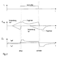
- the upper diagram indicates the electrical control command t i for the valve opening.
- the second middle diagram shows the effective magnetic forces F mag as a function of time t.
- the magnetic force of the second magnetic coil 4 is shown above the time axis, while below the time axis, the magnetic force of the first magnetic coil 2 is shown.
- the first magnetic coil 2 and the second magnetic coil 4 are energized simultaneously with an amount of approximately the same, but oppositely directed exciting current. Have both magnetic fields reached their full strength, the first solenoid coil 2 is turned off to open the fuel injection valve 1.
- the magnetic force of the second magnetic coil 4 attracts the armature 3 in the opening direction. If the armature 3 strikes the second core part 9, the magnetic force can be reduced to the necessary holding force by restoring the exciting current.
- the first solenoid coil 2 is energized again and at the same time the excitation current through the second solenoid 4 increases again.
- the first magnetic coil 2 again exerts a magnetic force on the armature 3, which moves the valve needle 13 in the closing direction together with the force of the return spring 17 via the first flange 14 and the second flange 15 after switching off the second solenoid coil 4.
- the magnetic force slowly decreases after switching off the exciting of the first solenoid 2 current to zero.
- the lower diagram in FIG. 2 represents the sum of the forces (magnetic force of the first and second magnetic coils 2 and 4 and the restoring force of the restoring spring 17).
- the magnetic force decreases again by the down-regulation of the exciting current to the holding current. However, it still exceeds the force of the return spring 17, so that the fuel injection valve 1 remains in the open position. If the first magnetic coil 2 is energized again in preparation for the closing operation, this initially has no effect on the prevailing force relationships. Only when the second solenoid 4 is turned off, only the magnetic force of the first solenoid 2 and the restoring force of the return spring 17 act in the same direction, whereby the fuel injection valve 1 is closed.
- Fig. 3 shows in a fragmentary sectional view of a detail of the embodiment described in Fig. 1 of the fuel injection valve 1 according to the invention in area III in Fig. 1.
- Fig. 3 shows in a fragmentary sectional view of a detail of the embodiment described in Fig. 1 of the fuel injection valve 1 according to the invention in area III in Fig. 1.
- the magnetic field lines 30 shown in FIG. 3 that, due to the geometry of the arrangement and the position of the non-magnetizable layer 11, they penetrate only the valve housing 20 in the region of the second magnet coil 4, the second core part 9 and the second armature part 5b.
- the portions of the magnetic field which penetrate the first anchor part 5a, the valve housing 20 in the region of the first magnet coil 2 and the first core part 8 are extremely small.
- the material of the non-magnetizable layer 11 and its position between the first magnetic coil 2 and the second magnetic coil 4 and their axial extent can be chosen so that the losses almost disappear.
- the position of the layer 11 allows the optimization of either the opening or closing operation, depending on whether the layer 11 is located closer to the first solenoid coil 2 or the second solenoid coil 4, since either the first armature part 5a or the second armature part 5b is stronger through the opening respective magnetic field is affected.
- the radial extent of the layer 11 does not need to divide the entire valve housing 20. It is sufficient to attach a slot to the desired radial extent in the valve housing 20 and to fill it with the non-magnetizable layer 11.
- FIGS. 4A and 4B the diffusion of the magnetic field is shown in FIGS. 4A and 4B in a radial sectional view, and the course of the eddy currents in the core part 8 is shown in a radial sectional illustration in FIGS. 5A and 5B.
- the sections run along the line IV-IV, VV in Fig. 1.
- FIG. 4A shows for comparison an unslotted core part 8 in a radial section along the line IV-IV and the diffusion of the magnetic field induced in the core part 8 of the first magnet coil 2.
- FIG. 4B shows the core part 8 in a radial section along the line IV-IV in a double-slotted region and the diffusion of the magnetic field induced in the core part 8 of the first magnetic coil 2.
- the core part 8 is divided into two parts 8a and 8b divided. Due to the slots 21 between the parts 8a and 8b, the magnetic field is not closed in a circular manner. As a result, losses can be kept lower, which has a positive effect on the driving power of the magnetic circuits.
- FIG. 5A shows, for comparison, the course of the eddy currents in a closed core part 8 in a radial section along the line V-V.
- the eddy currents are pronounced by the uninterrupted shape of the core part 8 and therefore influence the closing time of the fuel injection valve 1 considerably.
- Fig. 5B is a section along the line V-V through the double-slotted core part 8 is shown.
- the eddy currents do not pass through the slots 21, but in turn build up in the two parts 8a and 8b to closed eddy currents. The effect of the eddy currents is thereby reduced overall.
- the invention is not limited to the embodiment described, but is also suitable for outwardly opening fuel injectors. 1
Landscapes
- Engineering & Computer Science (AREA)
- Physics & Mathematics (AREA)
- Electromagnetism (AREA)
- Mechanical Engineering (AREA)
- General Engineering & Computer Science (AREA)
- Chemical & Material Sciences (AREA)
- Combustion & Propulsion (AREA)
- Fuel-Injection Apparatus (AREA)
Abstract
Claims (7)
- Injecteur de carburant (1), en particulier injecteur de carburant (1) pour des systèmes d'injection de carburant de moteurs à combustion interne, comprenant une première bobine magnétique (2) coopérant avec un induit (3), une deuxième bobine magnétique (4) coopérant avec l'induit (3), et une aiguille de soupape (13) reliée par liaison de force à l'induit (3) pour actionner un obturateur de soupape, la première bobine magnétique (2) exerçant sur l'induit (3) une force en direction de fermeture et la deuxième bobine magnétique (4), exerçant une force en direction d'ouverture,
caractérisé en ce qu'
un boîtier de soupape (20) ou des pièces de noyau (8, 9) servant de pôle intérieur de l'injecteur de carburant (1) présentent deux fentes (21) qui s'étendent en direction axiale, le long d'au moins une des bobines magnétiques (2, 4). - Injecteur de carburant selon la revendication 1,
caractérisé en ce qu'
une couche non magnétisable (11) se trouve entre la première bobine magnétique (2) et la deuxième bobine magnétique (4). - Injecteur de carburant selon la revendication 2,
caractérisé en ce que
la couche non magnétisable (11) divise une nervure (10) disposée entre la première bobine magnétique (2) et la deuxième bobine magnétique (4) en une première partie de nervure (10a) tournée vers la première bobine magnétique (2) et une deuxième partie de nervure (10b) tournée vers la deuxième bobine magnétique (4). - Injecteur de carburant selon la revendication 3,
caractérisé en ce que
la distance entre la première bobine magnétique (2) et la couche non magnétisable (11) et la distance entre la deuxième bobine magnétique (4) et la couche non magnétisable (11) sont de grandeurs différentes. - Injecteur de carburant selon la revendication 4,
caractérisé en ce que
la couche non magnétisable (11) se trouve plus près de la première bobine magnétique (2) que de la deuxième bobine magnétique (4). - Injecteur de carburant selon l'une quelconque des revendications 1 à 5,
caractérisé en ce que
l'induit (3) est divisé en deux parties, une première partie d'induit (5a) et une deuxième partie d'induit (5b), dont la première partie d'induit (5a) est en liaison active par une première bride (14) avec l'aiguille de soupape (13), et dont la deuxième partie d'induit (5b) est en liaison active par une deuxième bride (15) avec l'aiguille de soupape (13). - Injecteur de carburant selon la revendication 6,
caractérisé en ce que
la première partie d'induit (5a) et la deuxième partie d'induit (5b) présentent chacune un évidement conique (12).
Applications Claiming Priority (3)
| Application Number | Priority Date | Filing Date | Title |
|---|---|---|---|
| DE10004961A DE10004961B4 (de) | 2000-02-04 | 2000-02-04 | Brennstoffeinspritzventil und Verfahren zu dessen Betrieb |
| DE10004961 | 2000-02-04 | ||
| PCT/DE2001/000423 WO2001057390A1 (fr) | 2000-02-04 | 2001-02-02 | Soupape d'injection de carburant et procede pour faire fonctionner cette derniere |
Publications (2)
| Publication Number | Publication Date |
|---|---|
| EP1165960A1 EP1165960A1 (fr) | 2002-01-02 |
| EP1165960B1 true EP1165960B1 (fr) | 2007-07-25 |
Family
ID=7629840
Family Applications (1)
| Application Number | Title | Priority Date | Filing Date |
|---|---|---|---|
| EP01913566A Expired - Lifetime EP1165960B1 (fr) | 2000-02-04 | 2001-02-02 | Soupape d'injection de carburant |
Country Status (6)
| Country | Link |
|---|---|
| US (1) | US7021568B2 (fr) |
| EP (1) | EP1165960B1 (fr) |
| JP (1) | JP4741147B2 (fr) |
| KR (1) | KR20020023214A (fr) |
| DE (2) | DE10004961B4 (fr) |
| WO (1) | WO2001057390A1 (fr) |
Families Citing this family (16)
| Publication number | Priority date | Publication date | Assignee | Title |
|---|---|---|---|---|
| DE10155271A1 (de) * | 2001-11-09 | 2003-05-28 | Bosch Gmbh Robert | Common-Rail-Injektor |
| DE10235240B4 (de) * | 2002-08-01 | 2008-08-14 | Robert Bosch Gmbh | Magnetventilgesteuerte Einspritzdüse |
| US6892970B2 (en) * | 2002-12-18 | 2005-05-17 | Robert Bosch Gmbh | Fuel injector having segmented metal core |
| WO2006083977A1 (fr) * | 2005-02-02 | 2006-08-10 | Brp Us Inc. | Methode de commande d'un assemblage de pompage |
| FI119030B (fi) * | 2005-04-28 | 2008-06-30 | Waertsilae Finland Oy | Polttomoottorin polttoaineen syöttölaitteiston ohjausjärjestelmä |
| JP2008095521A (ja) * | 2006-10-06 | 2008-04-24 | Denso Corp | 電磁弁装置およびそれを用いた燃料噴射システム |
| US7628141B2 (en) * | 2007-02-26 | 2009-12-08 | Ford Global Technologies, Llc | Method for controlling an electrical actuator |
| JP4678545B2 (ja) * | 2008-07-25 | 2011-04-27 | 株式会社デンソー | モータ駆動装置 |
| DE102009003219A1 (de) * | 2009-05-19 | 2010-11-25 | Robert Bosch Gmbh | Aktiv schließendes Magnetventil für Magnetinjektoren |
| JP5537472B2 (ja) * | 2011-03-10 | 2014-07-02 | 日立オートモティブシステムズ株式会社 | 燃料噴射装置 |
| JP5939667B2 (ja) * | 2012-02-24 | 2016-06-22 | 株式会社ケーヒン | 電磁式燃料噴射弁 |
| DE102012218325A1 (de) * | 2012-10-09 | 2014-04-10 | Continental Automotive Gmbh | Aktuatoreinheit, insbesondere für die Einspritzung eines Kraftstoffs in einen Brennraum einer Verbrennungskraftmaschine |
| EP2835520B1 (fr) | 2013-08-09 | 2022-04-06 | Vitesco Technologies GmbH | Injecteur de carburant et procédé de fonctionnement |
| ITBO20150235A1 (it) * | 2015-05-05 | 2016-11-05 | Magneti Marelli Spa | Iniettore elettromagnetico di carburante con ottimizzazione delle saldature |
| JP6468988B2 (ja) * | 2015-11-23 | 2019-02-13 | 株式会社Soken | ソレノイド装置及びソレノイドシステム |
| DE102016206314B4 (de) * | 2016-04-14 | 2018-12-27 | Robert Bosch Gmbh | Kraftstoffeinspritzdüse |
Citations (1)
| Publication number | Priority date | Publication date | Assignee | Title |
|---|---|---|---|---|
| US3647177A (en) * | 1969-06-04 | 1972-03-07 | Gregor L Lang | Alternating current solenoids |
Family Cites Families (10)
| Publication number | Priority date | Publication date | Assignee | Title |
|---|---|---|---|---|
| DE2150099A1 (de) * | 1970-10-07 | 1972-05-25 | Hitachi Ltd | Treibstoff-Einspritzanlage |
| JPS60108559A (ja) * | 1983-11-16 | 1985-06-14 | Nippon Carbureter Co Ltd | 電磁燃料噴射弁 |
| DE3904448A1 (de) * | 1989-02-15 | 1990-08-16 | Bosch Gmbh Robert | Magnetanker |
| US5235954A (en) * | 1992-07-09 | 1993-08-17 | Anatoly Sverdlin | Integrated automated fuel system for internal combustion engines |
| US5494219A (en) * | 1994-06-02 | 1996-02-27 | Caterpillar Inc. | Fuel injection control valve with dual solenoids |
| JPH1077925A (ja) * | 1996-09-04 | 1998-03-24 | Hitachi Ltd | 燃料噴射装置及び方法 |
| JPH10274016A (ja) * | 1997-03-28 | 1998-10-13 | Fuji Heavy Ind Ltd | 電磁式動弁制御装置 |
| JP3707210B2 (ja) * | 1997-07-22 | 2005-10-19 | いすゞ自動車株式会社 | 燃料噴射制御装置 |
| US6036120A (en) * | 1998-03-27 | 2000-03-14 | General Motors Corporation | Fuel injector and method |
| JP2000002163A (ja) * | 1998-06-16 | 2000-01-07 | Nissan Motor Co Ltd | 燃料噴射装置及び電磁石装置 |
-
2000
- 2000-02-04 DE DE10004961A patent/DE10004961B4/de not_active Expired - Fee Related
-
2001
- 2001-02-02 EP EP01913566A patent/EP1165960B1/fr not_active Expired - Lifetime
- 2001-02-02 WO PCT/DE2001/000423 patent/WO2001057390A1/fr not_active Ceased
- 2001-02-02 JP JP2001556007A patent/JP4741147B2/ja not_active Expired - Fee Related
- 2001-02-02 KR KR1020017012657A patent/KR20020023214A/ko not_active Ceased
- 2001-02-02 US US09/958,372 patent/US7021568B2/en not_active Expired - Fee Related
- 2001-02-02 DE DE50112756T patent/DE50112756D1/de not_active Expired - Lifetime
Patent Citations (1)
| Publication number | Priority date | Publication date | Assignee | Title |
|---|---|---|---|---|
| US3647177A (en) * | 1969-06-04 | 1972-03-07 | Gregor L Lang | Alternating current solenoids |
Also Published As
| Publication number | Publication date |
|---|---|
| JP2003521634A (ja) | 2003-07-15 |
| JP4741147B2 (ja) | 2011-08-03 |
| DE50112756D1 (de) | 2007-09-06 |
| EP1165960A1 (fr) | 2002-01-02 |
| WO2001057390A1 (fr) | 2001-08-09 |
| US20020170986A1 (en) | 2002-11-21 |
| KR20020023214A (ko) | 2002-03-28 |
| US7021568B2 (en) | 2006-04-04 |
| DE10004961A1 (de) | 2001-08-09 |
| DE10004961B4 (de) | 2013-08-22 |
Similar Documents
| Publication | Publication Date | Title |
|---|---|---|
| EP1415083B1 (fr) | Soupape d'injection de carburant | |
| EP1255929B1 (fr) | Soupape d'injection de carburant et son procede de commande | |
| EP1137877B1 (fr) | Soupape d'injection de carburant | |
| DE69306781T2 (de) | Elektromagnetisches fluidventil | |
| EP1165960B1 (fr) | Soupape d'injection de carburant | |
| DE3855969T2 (de) | Elektromagnetisch betätigbare Vorrichtung zum schnellen Umschalten eines elektro-hydraulisch betätigten Kraftstoffeinspritzventils | |
| DE69624153T2 (de) | Verfahren zur Steuerung der anfänglichen Hublänge einer Kraftstoffdruckpumpe | |
| DE3638369C2 (de) | Elektromagnetisch gesteuertes Ventil für ein Kraftstoffeinspritzsystem | |
| EP0136594B1 (fr) | Electro-aimant | |
| EP0988447B1 (fr) | Soupape d'injection de carburant | |
| DE3544575C2 (fr) | ||
| DE69818184T2 (de) | Elektromagnetisch angesteuertes Ventil für eine Brennkraftmaschine | |
| DE68913209T2 (de) | Elektrisch betätigbares ventil für kraftstoff-einspritzanlagen für brennkraftmaschinen. | |
| DE19855547A1 (de) | Elektromagnetisch betätigbares Ventil | |
| DE69616448T2 (de) | Aufbau eines Magnetspaltes | |
| DE112006001605B4 (de) | Elektromagnetische Betätigungsvorrichtung und Verfahren zur Steuerung eines Strömungsmittelflusses | |
| DE29620741U1 (de) | Schmalbauender elektromagnetischer Aktuator | |
| EP3364015B1 (fr) | Soupape de commutation électromagnétique et pompe haute pression à carburant | |
| DE10300136A1 (de) | Kraftstoffeinspritzvorrichtung mit stationärem und bewegbarem Kern | |
| DE3501973A1 (de) | Brennstoff-einspritzduese | |
| EP0793004B1 (fr) | Commande électromagnétique de soupape | |
| EP1309792B1 (fr) | Soupape d'injection de carburant et procede pour actionner une soupape d'injection de carburant | |
| DE10005015B4 (de) | Verfahren zum Betreiben eines Brennstoffeinspritzventils | |
| DE3876770T2 (de) | Elektromagnetisches brennstoffeinspritzventil. | |
| DE19643430A1 (de) | Steuerventil |
Legal Events
| Date | Code | Title | Description |
|---|---|---|---|
| PUAI | Public reference made under article 153(3) epc to a published international application that has entered the european phase |
Free format text: ORIGINAL CODE: 0009012 |
|
| AK | Designated contracting states |
Kind code of ref document: A1 Designated state(s): AT BE CH CY DE DK ES FI FR GB GR IE IT LI LU MC NL PT SE TR |
|
| 17P | Request for examination filed |
Effective date: 20020211 |
|
| RBV | Designated contracting states (corrected) |
Designated state(s): DE FR IT |
|
| 17Q | First examination report despatched |
Effective date: 20041001 |
|
| RTI1 | Title (correction) |
Free format text: FUEL INJECTION VALVE |
|
| 17Q | First examination report despatched |
Effective date: 20041001 |
|
| GRAP | Despatch of communication of intention to grant a patent |
Free format text: ORIGINAL CODE: EPIDOSNIGR1 |
|
| GRAS | Grant fee paid |
Free format text: ORIGINAL CODE: EPIDOSNIGR3 |
|
| GRAA | (expected) grant |
Free format text: ORIGINAL CODE: 0009210 |
|
| AK | Designated contracting states |
Kind code of ref document: B1 Designated state(s): DE FR IT |
|
| REF | Corresponds to: |
Ref document number: 50112756 Country of ref document: DE Date of ref document: 20070906 Kind code of ref document: P |
|
| ET | Fr: translation filed | ||
| PLBE | No opposition filed within time limit |
Free format text: ORIGINAL CODE: 0009261 |
|
| STAA | Information on the status of an ep patent application or granted ep patent |
Free format text: STATUS: NO OPPOSITION FILED WITHIN TIME LIMIT |
|
| 26N | No opposition filed |
Effective date: 20080428 |
|
| PGFP | Annual fee paid to national office [announced via postgrant information from national office to epo] |
Ref country code: FR Payment date: 20140218 Year of fee payment: 14 Ref country code: IT Payment date: 20140224 Year of fee payment: 14 |
|
| PGFP | Annual fee paid to national office [announced via postgrant information from national office to epo] |
Ref country code: DE Payment date: 20150424 Year of fee payment: 15 |
|
| REG | Reference to a national code |
Ref country code: FR Ref legal event code: ST Effective date: 20151030 |
|
| PG25 | Lapsed in a contracting state [announced via postgrant information from national office to epo] |
Ref country code: IT Free format text: LAPSE BECAUSE OF NON-PAYMENT OF DUE FEES Effective date: 20150202 |
|
| PG25 | Lapsed in a contracting state [announced via postgrant information from national office to epo] |
Ref country code: FR Free format text: LAPSE BECAUSE OF NON-PAYMENT OF DUE FEES Effective date: 20150302 |
|
| REG | Reference to a national code |
Ref country code: DE Ref legal event code: R119 Ref document number: 50112756 Country of ref document: DE |
|
| PG25 | Lapsed in a contracting state [announced via postgrant information from national office to epo] |
Ref country code: DE Free format text: LAPSE BECAUSE OF NON-PAYMENT OF DUE FEES Effective date: 20160901 |