EP1165989B1 - Systeme d'embrayage d'une transmission - Google Patents
Systeme d'embrayage d'une transmission Download PDFInfo
- Publication number
- EP1165989B1 EP1165989B1 EP00922594A EP00922594A EP1165989B1 EP 1165989 B1 EP1165989 B1 EP 1165989B1 EP 00922594 A EP00922594 A EP 00922594A EP 00922594 A EP00922594 A EP 00922594A EP 1165989 B1 EP1165989 B1 EP 1165989B1
- Authority
- EP
- European Patent Office
- Prior art keywords
- clutch
- actuating device
- pressure medium
- accumulator
- return line
- Prior art date
- Legal status (The legal status is an assumption and is not a legal conclusion. Google has not performed a legal analysis and makes no representation as to the accuracy of the status listed.)
- Expired - Lifetime
Links
- 230000005540 biological transmission Effects 0.000 title claims description 18
- 230000002441 reversible effect Effects 0.000 claims description 8
- 230000008878 coupling Effects 0.000 description 5
- 238000010168 coupling process Methods 0.000 description 5
- 238000005859 coupling reaction Methods 0.000 description 5
- 239000012530 fluid Substances 0.000 description 5
- 230000006870 function Effects 0.000 description 5
- TZCXTZWJZNENPQ-UHFFFAOYSA-L barium sulfate Chemical compound [Ba+2].[O-]S([O-])(=O)=O TZCXTZWJZNENPQ-UHFFFAOYSA-L 0.000 description 3
- 210000003746 feather Anatomy 0.000 description 3
- 230000005489 elastic deformation Effects 0.000 description 2
- 241001295925 Gegenes Species 0.000 description 1
- 238000010276 construction Methods 0.000 description 1
- 230000007423 decrease Effects 0.000 description 1
- 230000003111 delayed effect Effects 0.000 description 1
- 238000010586 diagram Methods 0.000 description 1
- 238000005553 drilling Methods 0.000 description 1
- 238000009434 installation Methods 0.000 description 1
- 239000002655 kraft paper Substances 0.000 description 1
- 238000000034 method Methods 0.000 description 1
- 230000001960 triggered effect Effects 0.000 description 1
Images


Classifications
-
- F—MECHANICAL ENGINEERING; LIGHTING; HEATING; WEAPONS; BLASTING
- F16—ENGINEERING ELEMENTS AND UNITS; GENERAL MEASURES FOR PRODUCING AND MAINTAINING EFFECTIVE FUNCTIONING OF MACHINES OR INSTALLATIONS; THERMAL INSULATION IN GENERAL
- F16H—GEARING
- F16H61/00—Control functions within control units of change-speed- or reversing-gearings for conveying rotary motion ; Control of exclusively fluid gearing, friction gearing, gearings with endless flexible members or other particular types of gearing
- F16H61/04—Smoothing ratio shift
- F16H61/06—Smoothing ratio shift by controlling rate of change of fluid pressure
- F16H61/065—Smoothing ratio shift by controlling rate of change of fluid pressure using fluid control means
- F16H61/067—Smoothing ratio shift by controlling rate of change of fluid pressure using fluid control means using an accumulator
-
- F—MECHANICAL ENGINEERING; LIGHTING; HEATING; WEAPONS; BLASTING
- F16—ENGINEERING ELEMENTS AND UNITS; GENERAL MEASURES FOR PRODUCING AND MAINTAINING EFFECTIVE FUNCTIONING OF MACHINES OR INSTALLATIONS; THERMAL INSULATION IN GENERAL
- F16H—GEARING
- F16H61/00—Control functions within control units of change-speed- or reversing-gearings for conveying rotary motion ; Control of exclusively fluid gearing, friction gearing, gearings with endless flexible members or other particular types of gearing
- F16H61/02—Control functions within control units of change-speed- or reversing-gearings for conveying rotary motion ; Control of exclusively fluid gearing, friction gearing, gearings with endless flexible members or other particular types of gearing characterised by the signals used
- F16H61/0202—Control functions within control units of change-speed- or reversing-gearings for conveying rotary motion ; Control of exclusively fluid gearing, friction gearing, gearings with endless flexible members or other particular types of gearing characterised by the signals used the signals being electric
- F16H61/0204—Control functions within control units of change-speed- or reversing-gearings for conveying rotary motion ; Control of exclusively fluid gearing, friction gearing, gearings with endless flexible members or other particular types of gearing characterised by the signals used the signals being electric for gearshift control, e.g. control functions for performing shifting or generation of shift signal
- F16H61/0246—Control functions within control units of change-speed- or reversing-gearings for conveying rotary motion ; Control of exclusively fluid gearing, friction gearing, gearings with endless flexible members or other particular types of gearing characterised by the signals used the signals being electric for gearshift control, e.g. control functions for performing shifting or generation of shift signal characterised by initiating reverse gearshift
-
- F—MECHANICAL ENGINEERING; LIGHTING; HEATING; WEAPONS; BLASTING
- F16—ENGINEERING ELEMENTS AND UNITS; GENERAL MEASURES FOR PRODUCING AND MAINTAINING EFFECTIVE FUNCTIONING OF MACHINES OR INSTALLATIONS; THERMAL INSULATION IN GENERAL
- F16H—GEARING
- F16H63/00—Control outputs from the control unit to change-speed- or reversing-gearings for conveying rotary motion or to other devices than the final output mechanism
- F16H63/02—Final output mechanisms therefor; Actuating means for the final output mechanisms
- F16H63/30—Constructional features of the final output mechanisms
- F16H63/3023—Constructional features of the final output mechanisms the final output mechanisms comprising elements moved by fluid pressure
- F16H63/3026—Constructional features of the final output mechanisms the final output mechanisms comprising elements moved by fluid pressure comprising friction clutches or brakes
- F16H2063/3036—Constructional features of the final output mechanisms the final output mechanisms comprising elements moved by fluid pressure comprising friction clutches or brakes the clutch is actuated by springs and released by a fluid pressure
Definitions
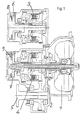
- the invention relates to a transmission in which clutches or brakes closed by spring force and hydraulic be opened again to drive the gearbox to connect or to with the output of the transmission separate or switch different translation levels.
- a reversing gear such as z. B. in Industrial trucks, such as forklifts, are used. in this connection will preferably be a clutch for forward travel and used a clutch for a reverse drive.
- a reversing gear such as z. B. in Industrial trucks, such as forklifts
- it can also be the input module of a multi-speed reverse gear act in particular in construction machinery, such as B. wheel loaders, backhoe loaders, etc., Is used.
- the generic DE 195 17 888 A1 discloses a reversible transmission which can be shifted under load, in which the reversing couplings are closed and hydraulically opened again by spring force and a hydraulically opened coupling can be switched to a closing process via a valve, the line to the actuating device of the coupling having a Memory and an aperture is connected.
- the volume of the memory is designed to be approximately large enough that it can accommodate the volume of the actuating device, so that the slats come into contact quickly after the circuit has been triggered. It is thus possible to move a previously opened clutch very quickly to a position in which the disks come into contact, since the volume in the actuating device is fed into the accumulator.
- the lamellae Due to elastic deformation of the components, however, the lamellae only come into contact when this residual pressure fluid is discharged from the actuating device of the clutch via a throttle point into the pressure medium reservoir when the accumulator is full. After the lamellae have come into contact and the accumulator is filled with this oil volume, the pressure-modulated load transfer of the clutch takes place by the oil of the accumulator flowing out through a diaphragm into a pressure medium reservoir and thus a pressure which is determined by the accumulator and also at the Actuator of the clutch is present, is still maintained for a certain period of time.
- the accumulator which is connected to the clutch, is filled with oil and slowly emptied via the orifice to the pressure medium reservoir. If a renewed switching takes place, in which the actuating device of the clutch is pressurized again and the accumulator has not yet completely discharged its oil volume via the orifice into the pressure medium reservoir, the accumulator is partially filled.
- JP 7-127785 A proposes that for a given piston stroke, the pressure chamber via a short-circuit line to the oil reservoir is connected; thus the installation space of an accumulator reduced.
- the present invention is based on the object to create a transmission with a clutch system, in which at least one clutch is closed by spring force and can be opened hydraulically again Load acceptance of the clutch is pressure-modulated and the Time until the clutch takes over regardless of the time interval of the circuits is.
- the clutch or brake is opened, by the actuator of the clutch or Brake is pressurized by using a Valve the actuating device of the clutch or brake is connected to a pressure medium source.
- the actuator the clutch or brake using a Valve connected to a memory and an orifice, so that a spring which on the actuator of the The clutch or brake acts, the oil volume in the actuator pushes into the store and thus the slats the clutch or brake to the system.
- the volume the memory is designed such that it is preferably the volume of the clutch actuator or brake corresponds.
- the volume of the memory can also be independent the volume of the clutch actuating device or brake, because the memory is no longer completely absorb the volume of the actuator must, since the pressure-modulated load transfer of the clutch only depends on the pressure-time curve, which is caused by the Design of the memory and the aperture with which the Memory is connected, and through which the pressure medium of the memory flows into the pressure medium reservoir, depends.
- the memory is preferably designed in such a way that that there is always a connection via the piston of the accumulator to the pressure medium reservoir arises when the memory is completely filled with pressure medium.
- the connection of the Storage or the actuator of the clutch with the pressure medium reservoir above a certain pressure level can also be done via a separate valve, however, which requires additional components.
Landscapes
- Engineering & Computer Science (AREA)
- General Engineering & Computer Science (AREA)
- Mechanical Engineering (AREA)
- Physics & Mathematics (AREA)
- Fluid Mechanics (AREA)
- Hydraulic Clutches, Magnetic Clutches, Fluid Clutches, And Fluid Joints (AREA)
- Control Of Transmission Device (AREA)
Claims (8)
- Transmission comprenant au moins un embrayage de commutation (3, 4) qui peut être actionné hydrauliquement dans le sens de l'ouverture à l'encontre d'une force élastique, un dispositif d'actionnement (6, 7) pouvant être relié à une conduite d'arrivée (14) et actionné dans le sens de la fermeture par une force élastique, un dispositif d'actionnement (6, 7) peut être relié à une conduite de retour (15) qui est en communication avec un accumulateur (17, 24) et avec un réservoir de fluide de pression (21) à travers un étranglement (22, 25), de sorte que le fluide de pression envoyé dans l'accumulateur (17, 24) et celui présent dans le dispositif d'actionnement (6, 7) s'écoulent à travers un étranglement (22, 25), caractérisée en ce que, lorsque le dispositif d'actionnement (6, 7) est relié à la conduite de retour (15), la conduite de retour (15) est en outre en communication directe avec le réservoir de fluide de pression (21) jusqu'à ce qu'un niveau de pression préalablement défini soit atteint dans le dispositif d'actionnement (6, 7) et en ce que, lorsque le niveau de pression préalablement défini est atteint, le fluide de pression contenu dans la conduite de retour (15) et dans l'accumulateur (17, 24) s'écoule dans le réservoir d'huile (21) exclusivement par l'étranglement (22, 25).
- Transmission selon la revendication 1, caractérisée en ce que l'accumulateur (17, 24) est un accumulateur à ressort comprenant un piston (26), dans lequel une surface frontale du piston (26) est reliée à une conduite de retour (15) du dispositif d'actionnement et une surface frontale opposée du piston est reliée à un réservoir de fluide de pression (21).
- Transmission selon la revendication 2, caractérisée en ce qu'au-dessus d'un niveau de pression préalablement défini, un piston (26) d'un accumulateur à ressort (17, 24) relie une conduite de retour (15) du dispositif d'actionnement (6, 7) à un réservoir de fluide de pression (21).
- Transmission selon la revendication 2, caractérisée en ce que un piston (26) d'un accumulateur à ressort (17, 24) comporte une fente annulaire (29) qui représente un étranglement (22, 25) à travers lequel, au-dessous d'un niveau de pression préalablement défini, une conduite de retour (15) du dispositif d'actionnement (6, 7) est reliée à un réservoir de fluide de pression (21).
- Transmission selon la revendication 1, caractérisée en ce que la transmission est une transmission réversible, dans laquelle au moins un embrayage de commutation (3, 4) peut être actionné pour une marche avant et au moins un embrayage de commutation (3, 4) peut être actionné pour une marche arrière.
- Transmission selon la revendication 5, caractérisée en ce que, sous l'effet de la mise hors pression d'un dispositif d'actionnement (6, 7) d'un embrayage de commutation (3, 4) pour une marche avant et d'un embrayage de commutation (3, 4) pour une marche arrière, les embrayages de commutation (3, 4) sont fermés et reliés l'un à l'autre de manière qu'un arbre de sortie (5) soit maintenu bloqué en rotation.
- Transmission selon la revendication 1, caractérisée en ce que l'accumulateur (17, 24) comporte un volume de fluide de pression qui correspond à peu près au volume d'huile qui est expulsé du dispositif d'actionnement (6, 7) jusqu'à ce que les disques d'un embrayage de commutation (3, 4) viennent en appui mutuel.
- Transmission selon la revendication 1, caractérisée par l'utilisation dans un véhicule de manutention, en particulier un chariot élévateur à fourche.
Applications Claiming Priority (3)
| Application Number | Priority Date | Filing Date | Title |
|---|---|---|---|
| DE19915557 | 1999-04-07 | ||
| DE19915557A DE19915557A1 (de) | 1999-04-07 | 1999-04-07 | Kupplungssystem in einem Getriebe |
| PCT/EP2000/002932 WO2000060257A1 (fr) | 1999-04-07 | 2000-04-01 | Systeme d'embrayage d'une transmission |
Publications (2)
| Publication Number | Publication Date |
|---|---|
| EP1165989A1 EP1165989A1 (fr) | 2002-01-02 |
| EP1165989B1 true EP1165989B1 (fr) | 2002-07-17 |
Family
ID=7903706
Family Applications (1)
| Application Number | Title | Priority Date | Filing Date |
|---|---|---|---|
| EP00922594A Expired - Lifetime EP1165989B1 (fr) | 1999-04-07 | 2000-04-01 | Systeme d'embrayage d'une transmission |
Country Status (8)
| Country | Link |
|---|---|
| US (1) | US6530463B1 (fr) |
| EP (1) | EP1165989B1 (fr) |
| JP (1) | JP2002541400A (fr) |
| KR (1) | KR20010105414A (fr) |
| BR (1) | BR0009422A (fr) |
| DE (2) | DE19915557A1 (fr) |
| ES (1) | ES2179030T3 (fr) |
| WO (1) | WO2000060257A1 (fr) |
Families Citing this family (6)
| Publication number | Priority date | Publication date | Assignee | Title |
|---|---|---|---|---|
| US7070036B2 (en) * | 2003-08-29 | 2006-07-04 | Muncie Power Products, Inc. | Power takeoff device |
| JP2008546972A (ja) * | 2005-07-01 | 2008-12-25 | ルーク ラメレン ウント クツプルングスバウ ベタイリグングス コマンディートゲゼルシャフト | 車両クラッチを操作する方法および装置 |
| DE102009005410B4 (de) * | 2009-01-19 | 2012-04-12 | Gkn Driveline International Gmbh | Aktuierungsanordnung und Verfahren zum Zuschalten einer Antriebsachse im Antriebsstrang eine Kraftfahrzeugs sowie Antriebsanordnung |
| DE102009001329B4 (de) | 2009-03-04 | 2018-05-24 | Zf Friedrichshafen Ag | Vorrichtung zum Betätigen einer Kupplung oder Bremse |
| DE102020203809B4 (de) * | 2020-03-24 | 2025-06-26 | Zf Friedrichshafen Ag | Getriebe mit mindestens einer hydraulisch betätigbaren Kupplung |
| CN111720535B (zh) * | 2020-06-29 | 2021-11-16 | 安徽江淮汽车集团股份有限公司 | 同步器控制方法、同步器控制装置及存储介质 |
Family Cites Families (16)
| Publication number | Priority date | Publication date | Assignee | Title |
|---|---|---|---|---|
| US2998732A (en) * | 1960-04-27 | 1961-09-05 | Deere & Co | Transmission and control therefor |
| US3149498A (en) * | 1961-06-15 | 1964-09-22 | Deere & Co | High-low-reverse transmission |
| US3425293A (en) * | 1967-02-13 | 1969-02-04 | Twin Disc Inc | Power transmission and control system therefor |
| US3613469A (en) * | 1970-04-29 | 1971-10-19 | Twin Disc Inc | Power transmission of the hydraulically actuated,friction clutch type |
| US3809201A (en) * | 1970-10-30 | 1974-05-07 | Kobe Steel Ltd | Modulating valve for vehicle transmission systems |
| US3715017A (en) * | 1970-10-30 | 1973-02-06 | Clark Equipment Co | Inching valve with bypass valve for filling clutches |
| US3741360A (en) * | 1971-12-29 | 1973-06-26 | Clark Equipment Co | Pump controlled pressure modulator for reversing clutches |
| US4583624A (en) * | 1984-12-10 | 1986-04-22 | Caterpillar Tractor Co. | Fluid system with selective differential pressure control |
| US4620560A (en) * | 1985-05-06 | 1986-11-04 | Caterpillar Inc. | Modulating relief valve with dual functioning load piston |
| US4751866A (en) * | 1986-10-03 | 1988-06-21 | Caterpillar Inc. | Ratio valve to control unloading of modulating relief valve |
| JPH02118234A (ja) | 1988-10-24 | 1990-05-02 | Yanmar Diesel Engine Co Ltd | 舶用多段減速逆転機の油圧供給装置 |
| US5119914A (en) * | 1991-10-15 | 1992-06-09 | General Motors Corporation | Accumulator and relay valve |
| US5199317A (en) * | 1992-06-22 | 1993-04-06 | Borg-Werner Automotive Transmission & Engine Components Corporation | Forward and reverse power shift transmission |
| JPH07127785A (ja) * | 1993-10-29 | 1995-05-16 | Mazda Motor Corp | 自動変速機のアキュムレータ |
| DE4405299A1 (de) * | 1994-02-19 | 1995-08-24 | Zahnradfabrik Friedrichshafen | Lastschaltbares Getriebe, insbesondere Zweigang-Planetengetriebe |
| DE19517888A1 (de) * | 1995-05-16 | 1996-11-21 | Zahnradfabrik Friedrichshafen | Unter Last schaltbares Wendegetriebe |
-
1999
- 1999-04-07 DE DE19915557A patent/DE19915557A1/de not_active Withdrawn
-
2000
- 2000-04-01 KR KR1020017012765A patent/KR20010105414A/ko not_active Withdrawn
- 2000-04-01 US US09/958,101 patent/US6530463B1/en not_active Expired - Fee Related
- 2000-04-01 WO PCT/EP2000/002932 patent/WO2000060257A1/fr not_active Ceased
- 2000-04-01 EP EP00922594A patent/EP1165989B1/fr not_active Expired - Lifetime
- 2000-04-01 ES ES00922594T patent/ES2179030T3/es not_active Expired - Lifetime
- 2000-04-01 DE DE50000291T patent/DE50000291D1/de not_active Expired - Lifetime
- 2000-04-01 BR BR0009422-6A patent/BR0009422A/pt not_active IP Right Cessation
- 2000-04-01 JP JP2000609720A patent/JP2002541400A/ja not_active Withdrawn
Also Published As
| Publication number | Publication date |
|---|---|
| DE19915557A1 (de) | 2000-10-12 |
| JP2002541400A (ja) | 2002-12-03 |
| ES2179030T3 (es) | 2003-01-16 |
| EP1165989A1 (fr) | 2002-01-02 |
| US6530463B1 (en) | 2003-03-11 |
| BR0009422A (pt) | 2001-12-26 |
| DE50000291D1 (de) | 2002-08-22 |
| KR20010105414A (ko) | 2001-11-28 |
| WO2000060257A1 (fr) | 2000-10-12 |
Similar Documents
| Publication | Publication Date | Title |
|---|---|---|
| EP3084273B1 (fr) | Système fluidique | |
| EP1384019B1 (fr) | Boite de vitesses commutable | |
| EP3227587A2 (fr) | Ensemble frein de stationnement | |
| DE102009020406B4 (de) | Drehmomentübertragungsanordnung | |
| DE4424790A1 (de) | Hydrauliknotsteuerung für eine zwischen einem Verbrennungsmotor und einem Getriebe angeordnete Reibkupplung | |
| EP0826118B1 (fr) | Boite d'inversion couplable sous charge | |
| DE60213152T2 (de) | Parksperreinrichtung für ein Kraftfahrzeug mit Leistungsgetriebe | |
| DE112006002365B4 (de) | Hydrauliksystem für die Steuerung zweier Aktuatoren und Getriebe mit einem solchen | |
| EP2016302B1 (fr) | Procede de commande d'un moyen d'actionnement | |
| EP1077825B1 (fr) | Dispositif d'entrainement | |
| EP1165989A1 (fr) | Systeme d'embrayage d'une transmission | |
| EP2734750B1 (fr) | Dispositif permettant d'actionner un embrayage de prise directe entraîné par friction d'un convertisseur de couple hydrodynamique | |
| EP0769110B1 (fr) | Systeme d'entrainement destine a un vehicule a moteur, en particulier a un engin de travaux publics | |
| EP0750552B1 (fr) | Transmission avec mode dégradé | |
| DE10120113A1 (de) | Auf hydraulischem Wege betätigbares Kupplungssystem | |
| DE102006059072B4 (de) | Vorrichtung und Verfahren zum Betätigen einer Kupplung | |
| DE19520447C1 (de) | Hydraulische Betätigungsvorrichtung mit Wegausgleich, für Reibungsbremsen mit Bremsband zum Schalten eines automatischen Getriebes von Kraftfahrzeugen | |
| DE4444381A1 (de) | Druckübersetzer | |
| DE19542766A1 (de) | Arbeitszylinder | |
| DE19919779A1 (de) | Hydraulisch betätigbare Kupplung | |
| DE3600873C1 (de) | Schaltvorrichtung fuer zwei Kupplungen zum Umschalten zwischen einachsigem Standardantrieb und zweiachsigem Allradantrieb bei einem Kraftfahrzeug mit zwei antreibbaren Fahrzeugachsen | |
| DE60130049T2 (de) | Vierradantrieb-Einschaltvorrichtung | |
| EP0757760B1 (fr) | Dispositif de reduction de la pression d'un embrayage couplable sous charge | |
| DE4122257C1 (fr) | ||
| DE102008042930A1 (de) | Hydraulische Kupplungsbetätigung |
Legal Events
| Date | Code | Title | Description |
|---|---|---|---|
| PUAI | Public reference made under article 153(3) epc to a published international application that has entered the european phase |
Free format text: ORIGINAL CODE: 0009012 |
|
| 17P | Request for examination filed |
Effective date: 20010627 |
|
| AK | Designated contracting states |
Kind code of ref document: A1 Designated state(s): AT BE CH CY DE DK ES FI FR GB GR IE IT LI LU MC NL PT SE |
|
| GRAG | Despatch of communication of intention to grant |
Free format text: ORIGINAL CODE: EPIDOS AGRA |
|
| 17Q | First examination report despatched |
Effective date: 20020204 |
|
| GRAG | Despatch of communication of intention to grant |
Free format text: ORIGINAL CODE: EPIDOS AGRA |
|
| GRAH | Despatch of communication of intention to grant a patent |
Free format text: ORIGINAL CODE: EPIDOS IGRA |
|
| GRAH | Despatch of communication of intention to grant a patent |
Free format text: ORIGINAL CODE: EPIDOS IGRA |
|
| GRAA | (expected) grant |
Free format text: ORIGINAL CODE: 0009210 |
|
| AK | Designated contracting states |
Kind code of ref document: B1 Designated state(s): BE DE ES FR GB IT |
|
| REG | Reference to a national code |
Ref country code: GB Ref legal event code: FG4D Free format text: NOT ENGLISH |
|
| GBT | Gb: translation of ep patent filed (gb section 77(6)(a)/1977) |
Effective date: 20020717 |
|
| REG | Reference to a national code |
Ref country code: IE Ref legal event code: FG4D Free format text: GERMAN |
|
| REF | Corresponds to: |
Ref document number: 50000291 Country of ref document: DE Date of ref document: 20020822 |
|
| ET | Fr: translation filed | ||
| REG | Reference to a national code |
Ref country code: ES Ref legal event code: FG2A Ref document number: 2179030 Country of ref document: ES Kind code of ref document: T3 |
|
| REG | Reference to a national code |
Ref country code: IE Ref legal event code: FD4D Ref document number: 1165989E Country of ref document: IE |
|
| PLBE | No opposition filed within time limit |
Free format text: ORIGINAL CODE: 0009261 |
|
| STAA | Information on the status of an ep patent application or granted ep patent |
Free format text: STATUS: NO OPPOSITION FILED WITHIN TIME LIMIT |
|
| 26N | No opposition filed |
Effective date: 20030422 |
|
| PGFP | Annual fee paid to national office [announced via postgrant information from national office to epo] |
Ref country code: GB Payment date: 20040331 Year of fee payment: 5 |
|
| PGFP | Annual fee paid to national office [announced via postgrant information from national office to epo] |
Ref country code: FR Payment date: 20040408 Year of fee payment: 5 |
|
| PGFP | Annual fee paid to national office [announced via postgrant information from national office to epo] |
Ref country code: ES Payment date: 20040416 Year of fee payment: 5 |
|
| PGFP | Annual fee paid to national office [announced via postgrant information from national office to epo] |
Ref country code: BE Payment date: 20040617 Year of fee payment: 5 |
|
| PG25 | Lapsed in a contracting state [announced via postgrant information from national office to epo] |
Ref country code: IT Free format text: LAPSE BECAUSE OF NON-PAYMENT OF DUE FEES Effective date: 20050401 Ref country code: GB Free format text: LAPSE BECAUSE OF NON-PAYMENT OF DUE FEES Effective date: 20050401 |
|
| PG25 | Lapsed in a contracting state [announced via postgrant information from national office to epo] |
Ref country code: ES Free format text: LAPSE BECAUSE OF NON-PAYMENT OF DUE FEES Effective date: 20050402 |
|
| PG25 | Lapsed in a contracting state [announced via postgrant information from national office to epo] |
Ref country code: BE Free format text: LAPSE BECAUSE OF NON-PAYMENT OF DUE FEES Effective date: 20050430 |
|
| BERE | Be: lapsed |
Owner name: *ZF FRIEDRICHSHAFEN A.G. Effective date: 20050430 |
|
| GBPC | Gb: european patent ceased through non-payment of renewal fee |
Effective date: 20050401 |
|
| PG25 | Lapsed in a contracting state [announced via postgrant information from national office to epo] |
Ref country code: FR Free format text: LAPSE BECAUSE OF NON-PAYMENT OF DUE FEES Effective date: 20051230 |
|
| REG | Reference to a national code |
Ref country code: FR Ref legal event code: ST Effective date: 20051230 |
|
| REG | Reference to a national code |
Ref country code: ES Ref legal event code: FD2A Effective date: 20050402 |
|
| BERE | Be: lapsed |
Owner name: *ZF FRIEDRICHSHAFEN A.G. Effective date: 20050430 |
|
| PGFP | Annual fee paid to national office [announced via postgrant information from national office to epo] |
Ref country code: DE Payment date: 20120411 Year of fee payment: 13 |
|
| PG25 | Lapsed in a contracting state [announced via postgrant information from national office to epo] |
Ref country code: DE Free format text: LAPSE BECAUSE OF NON-PAYMENT OF DUE FEES Effective date: 20131101 |
|
| REG | Reference to a national code |
Ref country code: DE Ref legal event code: R119 Ref document number: 50000291 Country of ref document: DE Effective date: 20131101 |