EP1166813A2 - Verfahren und Vorrichtung zur Auswertung des effektiven Strömungswiderstands in einem Beatmungskreislauf - Google Patents
Verfahren und Vorrichtung zur Auswertung des effektiven Strömungswiderstands in einem Beatmungskreislauf Download PDFInfo
- Publication number
- EP1166813A2 EP1166813A2 EP01110606A EP01110606A EP1166813A2 EP 1166813 A2 EP1166813 A2 EP 1166813A2 EP 01110606 A EP01110606 A EP 01110606A EP 01110606 A EP01110606 A EP 01110606A EP 1166813 A2 EP1166813 A2 EP 1166813A2
- Authority
- EP
- European Patent Office
- Prior art keywords
- breathing
- occlusion
- flow
- circuit
- value
- Prior art date
- Legal status (The legal status is an assumption and is not a legal conclusion. Google has not performed a legal analysis and makes no representation as to the accuracy of the status listed.)
- Withdrawn
Links
- 230000029058 respiratory gaseous exchange Effects 0.000 title claims abstract description 97
- 238000000034 method Methods 0.000 title claims description 26
- 238000005259 measurement Methods 0.000 claims abstract description 3
- 230000000977 initiatory effect Effects 0.000 claims description 2
- 239000007789 gas Substances 0.000 description 46
- 230000000694 effects Effects 0.000 description 6
- 230000001419 dependent effect Effects 0.000 description 3
- 238000011156 evaluation Methods 0.000 description 3
- 206010061688 Barotrauma Diseases 0.000 description 2
- 238000009530 blood pressure measurement Methods 0.000 description 2
- 210000004072 lung Anatomy 0.000 description 2
- 210000003437 trachea Anatomy 0.000 description 2
- 230000002411 adverse Effects 0.000 description 1
- 230000003444 anaesthetic effect Effects 0.000 description 1
- 230000003247 decreasing effect Effects 0.000 description 1
- 108700025647 major vault Proteins 0.000 description 1
- 238000012544 monitoring process Methods 0.000 description 1
- 230000001360 synchronised effect Effects 0.000 description 1
- 238000009423 ventilation Methods 0.000 description 1
Images



Classifications
-
- A—HUMAN NECESSITIES
- A61—MEDICAL OR VETERINARY SCIENCE; HYGIENE
- A61M—DEVICES FOR INTRODUCING MEDIA INTO, OR ONTO, THE BODY; DEVICES FOR TRANSDUCING BODY MEDIA OR FOR TAKING MEDIA FROM THE BODY; DEVICES FOR PRODUCING OR ENDING SLEEP OR STUPOR
- A61M16/00—Devices for influencing the respiratory system of patients by gas treatment, e.g. ventilators; Tracheal tubes
- A61M16/0051—Devices for influencing the respiratory system of patients by gas treatment, e.g. ventilators; Tracheal tubes with alarm devices
-
- A—HUMAN NECESSITIES
- A61—MEDICAL OR VETERINARY SCIENCE; HYGIENE
- A61M—DEVICES FOR INTRODUCING MEDIA INTO, OR ONTO, THE BODY; DEVICES FOR TRANSDUCING BODY MEDIA OR FOR TAKING MEDIA FROM THE BODY; DEVICES FOR PRODUCING OR ENDING SLEEP OR STUPOR
- A61M16/00—Devices for influencing the respiratory system of patients by gas treatment, e.g. ventilators; Tracheal tubes
- A61M16/021—Devices for influencing the respiratory system of patients by gas treatment, e.g. ventilators; Tracheal tubes operated by electrical means
- A61M16/022—Control means therefor
- A61M16/024—Control means therefor including calculation means, e.g. using a processor
-
- A—HUMAN NECESSITIES
- A61—MEDICAL OR VETERINARY SCIENCE; HYGIENE
- A61M—DEVICES FOR INTRODUCING MEDIA INTO, OR ONTO, THE BODY; DEVICES FOR TRANSDUCING BODY MEDIA OR FOR TAKING MEDIA FROM THE BODY; DEVICES FOR PRODUCING OR ENDING SLEEP OR STUPOR
- A61M16/00—Devices for influencing the respiratory system of patients by gas treatment, e.g. ventilators; Tracheal tubes
- A61M16/0003—Accessories therefor, e.g. sensors, vibrators, negative pressure
- A61M2016/0015—Accessories therefor, e.g. sensors, vibrators, negative pressure inhalation detectors
- A61M2016/0018—Accessories therefor, e.g. sensors, vibrators, negative pressure inhalation detectors electrical
- A61M2016/0021—Accessories therefor, e.g. sensors, vibrators, negative pressure inhalation detectors electrical with a proportional output signal, e.g. from a thermistor
-
- A—HUMAN NECESSITIES
- A61—MEDICAL OR VETERINARY SCIENCE; HYGIENE
- A61M—DEVICES FOR INTRODUCING MEDIA INTO, OR ONTO, THE BODY; DEVICES FOR TRANSDUCING BODY MEDIA OR FOR TAKING MEDIA FROM THE BODY; DEVICES FOR PRODUCING OR ENDING SLEEP OR STUPOR
- A61M16/00—Devices for influencing the respiratory system of patients by gas treatment, e.g. ventilators; Tracheal tubes
- A61M16/0003—Accessories therefor, e.g. sensors, vibrators, negative pressure
- A61M2016/003—Accessories therefor, e.g. sensors, vibrators, negative pressure with a flowmeter
- A61M2016/0033—Accessories therefor, e.g. sensors, vibrators, negative pressure with a flowmeter electrical
- A61M2016/0036—Accessories therefor, e.g. sensors, vibrators, negative pressure with a flowmeter electrical in the breathing tube and used in both inspiratory and expiratory phase
-
- A—HUMAN NECESSITIES
- A61—MEDICAL OR VETERINARY SCIENCE; HYGIENE
- A61M—DEVICES FOR INTRODUCING MEDIA INTO, OR ONTO, THE BODY; DEVICES FOR TRANSDUCING BODY MEDIA OR FOR TAKING MEDIA FROM THE BODY; DEVICES FOR PRODUCING OR ENDING SLEEP OR STUPOR
- A61M2205/00—General characteristics of the apparatus
- A61M2205/70—General characteristics of the apparatus with testing or calibration facilities
Definitions
- the present invention relates to a method for evaluating the effective flow resistance of a patient breathing circuit during mechanical breathing assistance and to a device for carrying out the method.
- a breathing tube such as an endotracheal or a tracheotomy tube
- a gas tubing system typically by means of a Y-Piece connector
- the breathing assist device is adapted to control the flow of gas through the breathing circuit to and from the patient's airways and thereby regulate the patient's breathing cycle.
- Over-pressurisation of the breathing gas provided to the patient through the breathing tube can cause barotrauma and so the gas pressure within the breathing circuit is usually monitored and used to control the assist device.
- Pressure sensors are typically provided within the assist device itself or at the Y-piece to monitor the gas pressures at the proximal end of the breathing tube.
- the breathing tube has a relatively narrow bore compared with the rest of the breathing circuit the breathing tube offers a large resistance to gas flow. This leads to inaccuracies between the pressures registered by the sensors and those extant within the lungs so that barotrauma may still occur due to too high a delivery pressure of the breathing gas. In other circumstances the delivery pressure of the breathing gas may be adjusted to too low a level so that efficient opening of the lungs no longer occurs.
- the device In order to reduce the effects of the flow resistance of the breathing circuit (principally the delivery tube) on the safe and effective operation of the assist device it is known to adapt the device to compensate the sensed delivery pressure for the breathing tube resistance and to use this compensated pressure value to control the delivery of breathing gas. In the known device this is done by a user inputting information relating to the breathing tube's resistance before the breathing assistance is started. This information may be in the form of the tube's length and internal diameter, from which a theoretical resistance can be calculated, or can be an actual calculated or measured resistance value determined before use.
- a method for evaluating an effective flow resistance of a breathing circuit during mechanical breathing assistance as described in and characterised by the present claim 1.
- the determined pressure drop at the onset of an occlusion may be assumed to effectively result from the resistance of a patient breathing tube which is present within the breathing circuit since the diameter of the tube is much smaller than the diameter of any other tubing component of the circuit and an indication of the tube resistance may be established from a pressure drop/flow relationship, which to a first approximation may be simply the determined pressure drop divided by the flow immediately before the introduction of the occlusion.
- an indication of the effective resistance of the breathing tube can be obtained automatically during breathing assistance to avoid the need for user input of the information.
- a calculation of ⁇ P/F 1.75 at a known flow or a calculation of a value of a linear rate of change of ⁇ P with F 1,75 ,that is, d ⁇ P/dF 1.75 may preferably be used to provide an indication of the tube resistance.
- the resistance is an actual resistance which thus reflects the reality of the breathing circuit in use.
- the method may be employed to monitor the breathing circuit during mechanical breathing assistance for changes in resistance which would indicate a leakage (decreased resistance) or a blockage (increased resistance) or may be employed to provide a resistance value of the actual breathing circuit which is used to compensate pressure measurements made by sensors in the breathing circuit.
- the occlusions are introduced during an expiration phase of a patient breathing cycle so as to reduce the effect of the evaluation method on breathing gas supply to the patient and so reduce any discomfort which the patient might otherwise experience.
- the different gas flows may be obtained by introducing the occlusions at different times within one or more expiration phases of a patient breathing cycle. Since the flow during an expiration phase varies with time then this has the advantage that the natural variation of flow with time over an expiration phase may be utilised to further reducing the adverse effects the use of the method of the present invention may have on the provision of mechanical breathing assistance.
- the evaluation may be made at different times within a single expiration phase so that a calculation of flow dependent rate of change of pressure drop may be made in a single breathing cycle.
- a calculation is to be made during an inspiration phase of a single breathing cycle then a ramped gas flow may be provided and occlusions similarly introduced throughout that phase.
- a patient ventilator 2 is shown interconnected with a breathing circuit 4 and a calculations unit 6 for evaluating an effective flow resistance within the breathing circuit 2 during the assisted ventilation of a patient.
- the patient ventilator 2 comprises a gas flow control unit 8 which connects to an inspiration line 10 and an expiration line 12 of the breathing circuit 4 via, respectively, an inspiration valve 14 and an expiration valve 16 within the ventilator 2.
- Valve actuators 18,20 within the ventilator 2 are operably connected to a respective one of the inspiration valve 14 and the expiration valve 16 and operate on receipt of a control signal to open and close their associated valve 14,16.
- the flow control unit 8 is connected to the actuators 18,20 and is adapted to provide control signals thereto in order to regulate the flow of inspiration and expiration gases in a known manner to provide a mechanical breathing cycle having controllable inspiration and expiration phases during one or more known control modes of operation of the ventilator 2.
- the patient breathing circuit 4 includes a Y-Piece 22, the separate limbs of which connect to the inspiration line 10 and the expiration line 12 and the common trunk of which connects to a small bore (typically between 5mm and 8mm) endotracheal tube 24.
- the endotracheal tube 24 has an open end 26 which, when breathing assistance is being provided by the ventilator 2, is inserted into the proximal airways of the patient.
- the calculations unit 6 functionally comprises a control unit 28 and an operably connected processor unit 30 which has associated therewith a memory unit 32. It will be appreciated from the subsequent description of the operation of these units 28,30,32 that they may be formed by a suitably programmed micro-computer.
- the control unit 28 is connected external the calculations unit 6 to a sensor unit 34, to the gas flow control unit 8, to the valve actuators 18,20 and to an alarm unit 36.
- the sensor unit 34 comprises both pressure and flow sensor elements and may be conveniently located within the common trunk of the Y-Piece 22 so as to be able to monitor pressures and flows of both inspiration and expiration gases within the breathing circuit 4.
- the sensor unit 34 is thus able to provide the control unit 28 (and optionally the gas flow control unit 8) with measured values of pressure and gas flow for either of the inspiration gas and the expiration gas as required.
- the control unit 28 is additionally operable to provide control signals to the valve actuators 18,20 to open and close the associated valves 14,16 and thereby introduce a temporary occlusion to gas flow within the breathing circuit 4. This may be achieved either directly or via the flow control unit 8 which normally operates to control these actuators 18,20 to provide a patient breathing cycle during normal operation of the ventilator 2.
- the control unit 28 may also be adapted to provide these control signals in dependence of timing signals from the gas flow control unit 8 of the ventilator 2 which are synchronised with the inspiration and the expiration phases of the breathing cycle being provided by the ventilator 2.
- valve components 14,18;20,16 which are typically already found in the patient ventilator 2 for controlling inspiration gas flow and expiration gas flow during a patient breathing cycle may be employed in the present invention.
- a specific valve arrangement (not shown) may be used to introduce occlusions to gas flow and may be placed at the Y-Piece 22 to reduce the number of extra components.
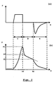
- the effective flow resistance of the breathing circuit 4 may be evaluated as follows with reference to Figs. 2:
- the gas flow control unit 8 of the ventilator 2 is arranged to provide in a volume control mode of operation a constant gas flow, F, to the patient during an inspiration phase, I.
- F a constant gas flow
- I an inspiration phase
- the inspiration valve 14 is open and the expiration valve 16 is closed under the control of the unit 8.
- the unit 8 is instructed by the control unit 28 to also close the inspiration valve 14 and initiate a "breath-hold", B, at a time, T0, and of a duration typically between 1 ms to 200 ms.
- the control unit 8 is instructed to operate to open the expiration valve 16 and an expiration phase, E, commences.
- the pressure, P1 as measured by the sensor unit 34 immediately before the breath-hold, B, is passed via the control unit 28 to the processor unit 30 where it may be stored in the memory 36 together with an associated gas flow value, F, as also measured by the sensor unit 34.
- the pressure measurement is repeated throughout the duration of the breath-hold and the "intermediate" pressure values are stored within memory 32 together with their associated times.
- a final pressure, P2 is recorded at a time, T2, at the end of the breath-hold and both values are again stored within the memory 32.
- the stored pressure and times are then accessed by the processor unit 30 which is adapted to calculate a pressure, P0, being extant within the breathing circuit 4 immediately upon introduction of the breath-hold at time, T0.
- the difference between the pressures immediately before (P1) and immediately after (P0) the breath-hold is taken to be the pressure drop ⁇ P resulting from the breathing circuit resistance, which is substantially due to the resistance of the endotracheal tube 24.
- the values ⁇ P and F are stored within the memory 32 and the process may be repeated at least once more with the flow control unit 8 operating to provide a different value of inspiration gas flow, F.
- the processor unit 30 then operates to recall the stored ⁇ P and F values and evaluate an effective flow resistance using these recalled values.
- the unit 30 may be programmed to determine a relationship between the pressure drop, ⁇ P, and the (obtained flow values, F) 1.75 , such as by calculating a value of a linear rate of change of determined pressure drop with (obtained flow value) 1,75 .
- This value provides a measure of the effective resistance of the breathing circuit 4.
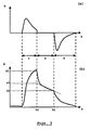
- Figs. 3 illustrates a typical flow characteristic over one breath during pressure support and shows a varying flow during inspiration, I.
- the breath hold, B is initiated based on an average of previous, typically three, breaths.
- the unit 8 operates to close flow valves 14,16 at a time T0 when a measurable quantity, such as inspiration time, inspiration flow, delivered volume, or inspiration pressure, in the present breath reaches a threshold based on the aforementioned average breath. Such a criteria for initiation a breath hold may be when the delivered volume reaches 90% of the expected total delivered volume based on an average of three preceding breaths.
- the calculations unit 6 then operates as described above with regard to the volume control mode of Figs. 2 to measure a final pressure, P2, at the end of the breath hold at time T2 and to extrapolate back to determine a pressure P0 at time T0.
- the pressure drop, ⁇ P, being P1-P0 is calculated and a tube resistance, R, may be determined from equation (3) above. Indeed if only an indication of tube resistance is required, for example if monitoring for changes in measured resistance, then a relationship of ⁇ P/F need only be determined.
- Fig. 4 The effect of breathing tube internal diameter on the calculated pressure drop, ⁇ P, as determined from breath-hold measurements described above, is shown in Fig. 4 for different inspiration flows, F.
- the relationship is shown in Fig. 4 as a plot of ⁇ P with F 1.75 .
- the effective flow resistance of the breathing circuit 4 may be evaluated during on or more expiration phases of mechanical breathing assistance such as during a single expiration phase as shown with reference to Figs. 5.
- the gas flow control unit 8 of the ventilator 2 is arranged to control the gas flow through the breathing circuit 4 to provide the patient with a breathing cycle comprising an inspiration phase, I and an expiration phase, E, with or without a breath-hold, B, according to the requirements of the patient.
- the unit 8 operates to close the inspiration valve 14 and open the expiration valve 16 in order to provide an expiration phase, E.
- a trigger signal is passed from the flow control unit 8 to the control unit 28 of the calculation unit 6 to indicate the onset of the expiration phase, E.
- the control unit 28 After a predetermined time (or flow as measured by the sensor unit 34) the control unit 28 operates to supply a signal to the actuator 20 to close the expiration valve 16 and an initiate an occlusion, O, to the flow of gas through the breathing circuit 4.
- a pressure, P1 as measured by the sensor unit 34 is passed via the control unit 28 to the processor unit 30 where it may be stored in the memory 36 together with an associated gas flow value, F1, as also measured by the sensor unit 34.
- F1 gas flow value
- second pressure, P1', as measured by the sensor unit 34 is passed via the control unit 28 to the processor unit 30 which can then calculate a value of a pressure drop ⁇ P1 (P1-P1') which is stored in memory 32 together with the flow value F1.
- P1-P1' a pressure drop
- F1-P1' the flow value
- These steps may be repeated at least once during the expiration phase, E, and pressure drops ⁇ P2, ⁇ P3 calculated and stored in memory 32 together with their associated flow values F2, F3.
- E may be employed in at least one other breath.
- the occlusion, O is then introduced at a different predetermined time or measured flow.
- the processor unit 30 may be adapted to recall the stored ⁇ P and F values and evaluate an effective flow resistance using these recalled values as described above in relation to the breath-hold process. Additionally or alternatively the processor unit 30 can be adapted to establish a relationship between the pressure drops and flow values as an evaluation of the effective flow resistance by constructing a digital representation of the pressure drop( ⁇ P)/flow(F) curve illustrated in Fig. 6. The processor unit 30 can be programmed to establish a "best-fit" to the so determined curve using either previously stored curves for breathing tubes of known internal diameter or calculated using equation (3). The value of the breathing tube diameter giving the best fit can then be used by the gas flow control unit 8 of the ventilator 2 during the provision of breathing assistance to compensate measured pressures for the effects of the breathing tube resistance.
Landscapes
- Health & Medical Sciences (AREA)
- Emergency Medicine (AREA)
- Pulmonology (AREA)
- Engineering & Computer Science (AREA)
- Anesthesiology (AREA)
- Biomedical Technology (AREA)
- Heart & Thoracic Surgery (AREA)
- Hematology (AREA)
- Life Sciences & Earth Sciences (AREA)
- Animal Behavior & Ethology (AREA)
- General Health & Medical Sciences (AREA)
- Public Health (AREA)
- Veterinary Medicine (AREA)
- Measurement Of The Respiration, Hearing Ability, Form, And Blood Characteristics Of Living Organisms (AREA)
- Respiratory Apparatuses And Protective Means (AREA)
- Measuring Volume Flow (AREA)
- Measuring Fluid Pressure (AREA)
Applications Claiming Priority (2)
| Application Number | Priority Date | Filing Date | Title |
|---|---|---|---|
| SE0002449 | 2000-06-29 | ||
| SE0002449A SE0002449D0 (sv) | 2000-06-29 | 2000-06-29 | Method and arrangement for evaluating effective flow resistance of a patient breathing circuit |
Publications (2)
| Publication Number | Publication Date |
|---|---|
| EP1166813A2 true EP1166813A2 (de) | 2002-01-02 |
| EP1166813A3 EP1166813A3 (de) | 2003-07-16 |
Family
ID=20280300
Family Applications (1)
| Application Number | Title | Priority Date | Filing Date |
|---|---|---|---|
| EP01110606A Withdrawn EP1166813A3 (de) | 2000-06-29 | 2001-04-30 | Verfahren und Vorrichtung zur Auswertung des effektiven Strömungswiderstands in einem Beatmungskreislauf |
Country Status (4)
| Country | Link |
|---|---|
| US (1) | US6510851B2 (de) |
| EP (1) | EP1166813A3 (de) |
| JP (1) | JP4938185B2 (de) |
| SE (1) | SE0002449D0 (de) |
Cited By (12)
| Publication number | Priority date | Publication date | Assignee | Title |
|---|---|---|---|---|
| WO2003075990A3 (en) * | 2002-03-08 | 2003-11-27 | Kaerys S A | A breathing apparatus with computation of the airflow provided to the patient using only pressure sensors |
| WO2006024532A1 (en) * | 2004-09-03 | 2006-03-09 | Ric Investments, Llc | Gas flow control in a ventilator |
| US7438073B2 (en) | 2002-03-08 | 2008-10-21 | Kaerys S.A. | Air assistance apparatus for computing the airflow provided by only means of pressure sensors |
| US7448383B2 (en) | 2002-03-08 | 2008-11-11 | Kaerys, S.A. | Air assistance apparatus providing fast rise and fall of pressure within one patient's breath |
| EP2106818A1 (de) * | 2008-03-31 | 2009-10-07 | Nellcor Puritan Bennett Llc | Systeme zum Ausgleich des Druckabfalls in einem Atemhilfsgerät |
| US20130006134A1 (en) * | 2011-06-30 | 2013-01-03 | Nellcor Puritan Bennett Llc | Methods and systems for monitoring volumetric carbon dioxide |
| EP2830497A4 (de) * | 2012-03-29 | 2015-12-16 | Jeffrey P Mansfield | System und verfahren zur verwendung akustischer reflektometrieinformationen in lüftungsvorrichtungen |
| US9707363B2 (en) | 2012-03-29 | 2017-07-18 | Sonarmed Inc. | System and method for use of acoustic reflectometry information in ventilation devices |
| CN110678217A (zh) * | 2017-05-29 | 2020-01-10 | 马奎特紧急护理公司 | 方法和麻醉呼吸设备 |
| US10668240B2 (en) | 2015-03-26 | 2020-06-02 | Sonarmed Inc. | Acoustical guidance and monitoring system |
| US10729621B2 (en) | 2016-05-31 | 2020-08-04 | Sonarmed Inc. | Acoustic reflectometry device in catheters |
| US11324906B2 (en) | 2017-08-04 | 2022-05-10 | Covidien Lp | Acoustic guided suction systems, devices, and methods |
Families Citing this family (25)
| Publication number | Priority date | Publication date | Assignee | Title |
|---|---|---|---|---|
| US5038040A (en) * | 1989-09-22 | 1991-08-06 | Agmed Inc. | Soil test apparatus |
| SE0002849D0 (sv) * | 2000-08-08 | 2000-08-08 | Siemens Elema Ab | Ventilator |
| SE0102221D0 (sv) * | 2001-06-19 | 2001-06-19 | Siemens Elema Ab | Method for assessing pulmonary stress and a breathing apparatus |
| CA2379353C (en) * | 2002-03-28 | 2012-07-31 | Joseph Fisher | A new method for continuous measurement of flux of gases in the lungs during breathing |
| WO2004073779A2 (en) * | 2003-02-18 | 2004-09-02 | Joseph Fisher | Breathing circuits to facilitate the measurement of cardiac output during controlled and spontaneous ventilation |
| US8469026B2 (en) * | 2005-06-09 | 2013-06-25 | Maquet Critical Care Ab | Ventilator operable in a bioelectric signal-dependent mode, with automatic switching to another mode upon dropout of the bioelectric signal |
| US7798143B1 (en) * | 2005-07-07 | 2010-09-21 | Ric Investments, Llc | Respiratory treatment device with patient reporting |
| EP2017586A1 (de) * | 2007-07-20 | 2009-01-21 | Map-Medizintechnologie GmbH | Monitor für CPAP-/Beatmungsvorrichtung |
| AU2008288795B2 (en) * | 2007-08-22 | 2014-03-06 | The Research Foundation Of The State University Of New York | Breathing-gas delivery and sharing system and method |
| CN102892449B (zh) * | 2010-05-11 | 2016-04-20 | 皇家飞利浦电子股份有限公司 | 压力支持系统中的感应系数补偿 |
| CN102946933B (zh) * | 2010-06-22 | 2016-09-14 | 皇家飞利浦电子股份有限公司 | 呼吸接口装置 |
| CN103079621B (zh) * | 2010-06-30 | 2015-09-16 | 圣米高医院 | 用于通过气管内贯流的与患者同步的通气辅助的方法和系统 |
| US9370633B2 (en) | 2010-09-10 | 2016-06-21 | Carefusion 207, Inc. | Nasal intermittent mandatory ventilation (NIMV) control system in a ventilator |
| DE102011118265B4 (de) * | 2011-11-11 | 2016-06-30 | Drägerwerk AG & Co. KGaA | Beatmungsvorrichtung |
| EP2747643B1 (de) * | 2011-12-30 | 2024-05-15 | Koninklijke Philips N.V. | In respiratorische behandlungsvorrichtungen integrierte atemwegsimpedanzmessung |
| WO2013140333A1 (en) * | 2012-03-21 | 2013-09-26 | Koninklijke Philips N.V. | System and method for controlling insufflation pressure during inexsufflation |
| US9950129B2 (en) | 2014-10-27 | 2018-04-24 | Covidien Lp | Ventilation triggering using change-point detection |
| GB2540444B (en) * | 2015-12-07 | 2017-11-29 | Dobbing Christopher | Respirator mask management system |
| DE102016012824A1 (de) * | 2016-10-25 | 2018-04-26 | Drägerwerk AG & Co. KGaA | Verfahren und Vorrichtung zum adaptiven Regeln eines positiv endexspiratorischen Drucks (PEEP) |
| EP3793656A1 (de) | 2018-05-14 | 2021-03-24 | Covidien LP | Systeme und verfahren zur erfassung der atemleistung unter verwendung von signalverzerrung |
| US11752287B2 (en) | 2018-10-03 | 2023-09-12 | Covidien Lp | Systems and methods for automatic cycling or cycling detection |
| CN112156297A (zh) * | 2018-10-26 | 2021-01-01 | 北京怡和嘉业医疗科技股份有限公司 | 一种通气治疗设备及控制方法 |
| CN109999292A (zh) * | 2019-03-29 | 2019-07-12 | 北京怡和嘉业医疗科技股份有限公司 | 用于通气设备的控制系统、方法及通气设备 |
| CN111407283A (zh) * | 2020-04-10 | 2020-07-14 | 苏州健通医疗科技有限公司 | 一种肺功能手持测量阻断装置、测量装置和系统 |
| DE102020123138B3 (de) * | 2020-09-04 | 2021-11-04 | Drägerwerk AG & Co. KGaA | Verfahren und Vorrichtung zur automatischen Festlegung der Sollfrequenz eines Beatmungsgeräts |
Citations (1)
| Publication number | Priority date | Publication date | Assignee | Title |
|---|---|---|---|---|
| US5876352A (en) | 1997-05-17 | 1999-03-02 | Dragerwerk Ag | Process for determining the mechanical properties of the respiratory system of a respirated patient and device for carrying out the process |
Family Cites Families (5)
| Publication number | Priority date | Publication date | Assignee | Title |
|---|---|---|---|---|
| GB8920499D0 (en) * | 1989-09-11 | 1989-10-25 | Micro Medical Ltd | Apparatus for measuring airway resistance |
| DE19734203A1 (de) * | 1997-08-07 | 1999-02-25 | Greiner Wolfgang Dr | Vorrichtung zur Bestimmung des Atemwiderstandes |
| US6257234B1 (en) * | 1998-08-21 | 2001-07-10 | Respironics, Inc. | Apparatus and method for determining respiratory mechanics of a patient and for controlling a ventilator based thereon |
| SE9802827D0 (sv) * | 1998-08-25 | 1998-08-25 | Siemens Elema Ab | Ventilator |
| US6390091B1 (en) * | 1999-02-03 | 2002-05-21 | University Of Florida | Method and apparatus for controlling a medical ventilator |
-
2000
- 2000-06-29 SE SE0002449A patent/SE0002449D0/xx unknown
-
2001
- 2001-04-30 EP EP01110606A patent/EP1166813A3/de not_active Withdrawn
- 2001-06-26 US US09/892,025 patent/US6510851B2/en not_active Expired - Lifetime
- 2001-06-29 JP JP2001199497A patent/JP4938185B2/ja not_active Expired - Lifetime
Patent Citations (1)
| Publication number | Priority date | Publication date | Assignee | Title |
|---|---|---|---|---|
| US5876352A (en) | 1997-05-17 | 1999-03-02 | Dragerwerk Ag | Process for determining the mechanical properties of the respiratory system of a respirated patient and device for carrying out the process |
Cited By (21)
| Publication number | Priority date | Publication date | Assignee | Title |
|---|---|---|---|---|
| US7500481B2 (en) | 2002-03-08 | 2009-03-10 | Kaerys S.A. | Apparatus to assist a patient's breathing with a variable ramp period to rise to treatment pressure |
| WO2003075990A3 (en) * | 2002-03-08 | 2003-11-27 | Kaerys S A | A breathing apparatus with computation of the airflow provided to the patient using only pressure sensors |
| US7438073B2 (en) | 2002-03-08 | 2008-10-21 | Kaerys S.A. | Air assistance apparatus for computing the airflow provided by only means of pressure sensors |
| US7448383B2 (en) | 2002-03-08 | 2008-11-11 | Kaerys, S.A. | Air assistance apparatus providing fast rise and fall of pressure within one patient's breath |
| US8161970B2 (en) | 2004-09-03 | 2012-04-24 | Ric Investments, Llc | Gas flow control in a ventilator |
| WO2006024532A1 (en) * | 2004-09-03 | 2006-03-09 | Ric Investments, Llc | Gas flow control in a ventilator |
| EP2106818A1 (de) * | 2008-03-31 | 2009-10-07 | Nellcor Puritan Bennett Llc | Systeme zum Ausgleich des Druckabfalls in einem Atemhilfsgerät |
| US20130006134A1 (en) * | 2011-06-30 | 2013-01-03 | Nellcor Puritan Bennett Llc | Methods and systems for monitoring volumetric carbon dioxide |
| US10751492B2 (en) | 2012-03-29 | 2020-08-25 | Sonarmed Inc. | System and method for use of acoustic reflectometry information in ventilation devices |
| EP2830497A4 (de) * | 2012-03-29 | 2015-12-16 | Jeffrey P Mansfield | System und verfahren zur verwendung akustischer reflektometrieinformationen in lüftungsvorrichtungen |
| US9707363B2 (en) | 2012-03-29 | 2017-07-18 | Sonarmed Inc. | System and method for use of acoustic reflectometry information in ventilation devices |
| US12337110B2 (en) | 2012-03-29 | 2025-06-24 | Covidien Lp | System and method for use of acoustic reflectometry information in ventilation devices |
| US11696993B2 (en) | 2012-03-29 | 2023-07-11 | Covidien Lp | System and method for use of acoustic reflectometry information in ventilation devices |
| US11517695B2 (en) | 2015-03-26 | 2022-12-06 | Covidien Lp | Acoustical guidance and monitoring system |
| US10668240B2 (en) | 2015-03-26 | 2020-06-02 | Sonarmed Inc. | Acoustical guidance and monitoring system |
| US11878117B2 (en) | 2015-03-26 | 2024-01-23 | Covidien Lp | Acoustical guidance and monitoring system |
| US10729621B2 (en) | 2016-05-31 | 2020-08-04 | Sonarmed Inc. | Acoustic reflectometry device in catheters |
| US11654087B2 (en) | 2016-05-31 | 2023-05-23 | Covidien Lp | Acoustic reflectometry device in catheters |
| CN110678217A (zh) * | 2017-05-29 | 2020-01-10 | 马奎特紧急护理公司 | 方法和麻醉呼吸设备 |
| US11324906B2 (en) | 2017-08-04 | 2022-05-10 | Covidien Lp | Acoustic guided suction systems, devices, and methods |
| US12377234B2 (en) | 2017-08-04 | 2025-08-05 | Covidien Lp | Acoustic guided suction systems, devices, and methods |
Also Published As
| Publication number | Publication date |
|---|---|
| SE0002449D0 (sv) | 2000-06-29 |
| EP1166813A3 (de) | 2003-07-16 |
| JP4938185B2 (ja) | 2012-05-23 |
| US20020020410A1 (en) | 2002-02-21 |
| JP2002143309A (ja) | 2002-05-21 |
| US6510851B2 (en) | 2003-01-28 |
Similar Documents
| Publication | Publication Date | Title |
|---|---|---|
| US6510851B2 (en) | Method and arrangement for evaluating effective flow resistance of patient breathing circuit | |
| US8353291B2 (en) | Systems and methods for compensating for pressure drop in a breathing assistance system | |
| EP0968020B1 (de) | Beatmungsgerät mit einem System für Undichtheits- und Okklusionsdetektion | |
| JP4307811B2 (ja) | 呼吸システムの肺力学の検査のためのオペレーティングシステムおよび呼吸装置システム | |
| US6240920B1 (en) | Method for determining a parameter related to spontaneous breathing efforts by a subject, and breathing-assist apparatus operating in accordance with the method | |
| US8528554B2 (en) | Inverse sawtooth pressure wave train purging in medical ventilators | |
| CA2036184C (en) | System and method for flow triggering of pressure supported ventilation | |
| EP2401015B1 (de) | Druckunterstützungssystem mit maschineller beatmung | |
| US6360741B2 (en) | Pressure support system with a low leak alarm and method of using same | |
| EP0835670A2 (de) | Beatmungsgeräte | |
| US20110087123A9 (en) | Method and apparatus for airway compensation control | |
| EP2774646A1 (de) | Gerät mit verbessertem Atemunterstützungszyklus | |
| US20110146681A1 (en) | Adaptive Flow Sensor Model | |
| JPH04506019A (ja) | 医療用換気器具における又はこれに関する改良 | |
| CA2297067A1 (en) | Medical dosing device having dosing chamber with a pressure sensor | |
| JP2019534074A (ja) | 全ての呼吸筋反動生成圧が消失することを可能にするための、圧力制御された呼吸を用いた肺コンプライアンス及び肺抵抗の推定 | |
| CN107970510B (zh) | 用于适当地调节呼气末正压(peep)的方法和设备 | |
| US20170312463A1 (en) | System and method for accurate estimation of intentional and unintentional leaks in flow generation systems | |
| JP2020535909A (ja) | 自発呼吸を考慮した、流量センサのエラーの自動検出を伴う人工呼吸器 | |
| CN110892486B (zh) | 经由虚拟压力触发机制的通气机气体递送吸入 | |
| US20250176850A1 (en) | Fluid conyeving device for introducing fluid into and/or removing fluid from an esophageal balloon catheter | |
| JPH07116254A (ja) | 呼吸補助法 |
Legal Events
| Date | Code | Title | Description |
|---|---|---|---|
| PUAI | Public reference made under article 153(3) epc to a published international application that has entered the european phase |
Free format text: ORIGINAL CODE: 0009012 |
|
| AK | Designated contracting states |
Kind code of ref document: A2 Designated state(s): AT BE CH CY DE DK ES FI FR GB GR IE IT LI LU MC NL PT SE TR |
|
| AX | Request for extension of the european patent |
Free format text: AL;LT;LV;MK;RO;SI |
|
| PUAL | Search report despatched |
Free format text: ORIGINAL CODE: 0009013 |
|
| AK | Designated contracting states |
Designated state(s): AT BE CH CY DE DK ES FI FR GB GR IE IT LI LU MC NL PT SE TR |
|
| AX | Request for extension of the european patent |
Extension state: AL LT LV MK RO SI |
|
| 17P | Request for examination filed |
Effective date: 20031208 |
|
| RAP1 | Party data changed (applicant data changed or rights of an application transferred) |
Owner name: MAQUET CRITICAL CARE AB |
|
| AKX | Designation fees paid |
Designated state(s): DE FR |
|
| 17Q | First examination report despatched |
Effective date: 20050310 |
|
| 17Q | First examination report despatched |
Effective date: 20050310 |
|
| STAA | Information on the status of an ep patent application or granted ep patent |
Free format text: STATUS: THE APPLICATION IS DEEMED TO BE WITHDRAWN |
|
| 18D | Application deemed to be withdrawn |
Effective date: 20170503 |