EP1167008A2 - Vorrichtung zum Zuführen von Packungszuschnitten - Google Patents
Vorrichtung zum Zuführen von Packungszuschnitten Download PDFInfo
- Publication number
- EP1167008A2 EP1167008A2 EP01113358A EP01113358A EP1167008A2 EP 1167008 A2 EP1167008 A2 EP 1167008A2 EP 01113358 A EP01113358 A EP 01113358A EP 01113358 A EP01113358 A EP 01113358A EP 1167008 A2 EP1167008 A2 EP 1167008A2
- Authority
- EP
- European Patent Office
- Prior art keywords
- conveyor roller
- lever
- blank
- roller
- conveyor
- Prior art date
- Legal status (The legal status is an assumption and is not a legal conclusion. Google has not performed a legal analysis and makes no representation as to the accuracy of the status listed.)
- Granted
Links
- 230000033001 locomotion Effects 0.000 claims abstract description 37
- 238000004806 packaging method and process Methods 0.000 claims abstract description 5
- 238000004519 manufacturing process Methods 0.000 claims description 4
- 235000019504 cigarettes Nutrition 0.000 claims description 3
- 238000013022 venting Methods 0.000 claims description 2
- 230000005540 biological transmission Effects 0.000 description 10
- 238000005520 cutting process Methods 0.000 description 9
- 238000007789 sealing Methods 0.000 description 5
- 238000000034 method Methods 0.000 description 4
- 210000000056 organ Anatomy 0.000 description 3
- 230000001360 synchronised effect Effects 0.000 description 2
- 210000001520 comb Anatomy 0.000 description 1
- 230000001447 compensatory effect Effects 0.000 description 1
- 238000011109 contamination Methods 0.000 description 1
- 230000000977 initiatory effect Effects 0.000 description 1
- 239000000314 lubricant Substances 0.000 description 1
- 238000005461 lubrication Methods 0.000 description 1
- 238000012423 maintenance Methods 0.000 description 1
- 239000000463 material Substances 0.000 description 1
- 239000002245 particle Substances 0.000 description 1
- 239000000700 radioactive tracer Substances 0.000 description 1
- 238000005096 rolling process Methods 0.000 description 1
- 238000009423 ventilation Methods 0.000 description 1
Images



Classifications
-
- B—PERFORMING OPERATIONS; TRANSPORTING
- B65—CONVEYING; PACKING; STORING; HANDLING THIN OR FILAMENTARY MATERIAL
- B65B—MACHINES, APPARATUS OR DEVICES FOR, OR METHODS OF, PACKAGING ARTICLES OR MATERIALS; UNPACKING
- B65B19/00—Packaging rod-shaped or tubular articles susceptible to damage by abrasion or pressure, e.g. cigarettes, cigars, macaroni, spaghetti, drinking straws or welding electrodes
- B65B19/02—Packaging cigarettes
- B65B19/22—Wrapping the cigarettes; Packaging the cigarettes in containers formed by folding wrapping material around formers
- B65B19/228—Preparing and feeding blanks
-
- B—PERFORMING OPERATIONS; TRANSPORTING
- B65—CONVEYING; PACKING; STORING; HANDLING THIN OR FILAMENTARY MATERIAL
- B65H—HANDLING THIN OR FILAMENTARY MATERIAL, e.g. SHEETS, WEBS, CABLES
- B65H3/00—Separating articles from piles
- B65H3/08—Separating articles from piles using pneumatic force
- B65H3/0808—Suction grippers
- B65H3/085—Suction grippers separating from the bottom of pile
- B65H3/0858—Suction grippers separating from the bottom of pile this action resulting merely in a curvature of each article being separated
- B65H3/0866—Suction grippers separating from the bottom of pile this action resulting merely in a curvature of each article being separated the final separation being performed between rollers
-
- B—PERFORMING OPERATIONS; TRANSPORTING
- B31—MAKING ARTICLES OF PAPER, CARDBOARD OR MATERIAL WORKED IN A MANNER ANALOGOUS TO PAPER; WORKING PAPER, CARDBOARD OR MATERIAL WORKED IN A MANNER ANALOGOUS TO PAPER
- B31B—MAKING CONTAINERS OF PAPER, CARDBOARD OR MATERIAL WORKED IN A MANNER ANALOGOUS TO PAPER
- B31B50/00—Making rigid or semi-rigid containers, e.g. boxes or cartons
- B31B50/02—Feeding or positioning sheets, blanks or webs
- B31B50/04—Feeding sheets or blanks
- B31B50/06—Feeding sheets or blanks from stacks
- B31B50/062—Feeding sheets or blanks from stacks from the underside of a magazine
Definitions
- the invention relates to a device for handling blanks in a packaging machine, especially for the manufacture of cigarette packs of the type Hinged box, with a blank magazine, which the blanks individually by a removal unit can be removed with a conveyor roller and fed to a discharge conveyor, wherein the conveyor roller can be moved back and forth on an open (lower) side of the blank magazine and carries a cut along the circumference.
- This gearbox is not without problems. Above all, the largely open sled guide is exposed to the risk of contamination. It is also a constant, sufficient Lubrication required to transfer lubricant particles to the Guide cuts and parts of the unit.
- the invention is therefore based on the object of a device for handling of blanks, in particular for removal from the blank magazine and feeding to a conveyor, propose that with high performance less maintenance requires and reduces the risk of pollution:
- the device according to the invention is characterized in that that the conveyor roller is attached to a swivel arm that is driven by a gear is driven back and forth so that the conveyor roller along a straight line Movement path is moved back and forth.
- the essence of the invention is to eliminate the carriage guide for the conveyor roller and instead use a mechanism that can move linearly without a slide the conveyor roller guaranteed.
- a crank mechanism for the movement of the swivel arm in connection with is advantageous a differential, which is designed so that by the swivel arm caused movement of the conveyor roller along an arc and balanced in a exact linear movement is converted.
- the differential includes a rotating one Curve connection, which is connected to the swivel arm via a compensating lever is, the compensating lever designed as a two-armed lever due to corresponding Adjustment movements of the swivel arm the linear movement of the conveyor roller causes.
- control elements required in the transmission according to the invention namely in particular Track rollers or tracer rollers in connection with cam tracks, grooves or the like, are housed separately in a closed housing and can be adequately lubricated without affecting the environment.
- the device for two-lane operation can be designed, with two blank magazines at a distance from each other are positioned, which corresponds to the distance between subsequent cutting tracks.
- Each Cutting magazine is assigned a conveyor role. Both conveyor roles are shared by one Gearbox can be moved back and forth at the same time.
- the embodiment shown in the drawings is an assembly for packaging machines for the manufacture of cigarette packs of the hinged box type.
- blanks 10 are processed which are characteristic of this type of pack Have contour (Fig. 6).
- Side tabs are of interest in this context 11, 12 and a lid inner tab 13.
- the blanks 10 designed in this or a different manner can be found in a blank magazine.
- the blanks 10 are individually removed from the blank magazines 14, 15. In the a slightly inclined position arranged blank magazines 14, 15 are on the underside open. The respective lower blank 10 is captured by a removal member and taken from the blank magazine 14, 15. The blank 10 is sent to a conveyor passed, in the present case to conveyor rollers 16, the blank 10 along remove a downwardly inclined cutting path 17.
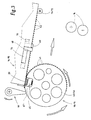
- the removal member is a conveyor roller 18, 19 on the open side of the blank magazine 14, 15 is moved back and forth, namely from a recording position according to 3 into a transfer position according to FIG. 5.
- the conveyor roller 18, 19 detects each a blank 10 with a gripping member, namely with a suction head 20. This is on Scope of the conveyor roller 18, 19 effective.
- a blank 10 is captured in an end region, namely in the area of the lid inner tab 13.
- the bottom blank 10 is captured. This goes down thereby on the circumference of the conveyor roller 18, 19.
- the conveyor roller 18, 19 returns to the starting position by counter-movement back.
- the back and forth movement of the conveyor roller 18, 19 takes place exactly along one straight line of motion - based on a central axis of rotation.
- a special gear provided, which consists of a motion gear 22 and a Differential gear 23 exists.
- the motion gear 22 is a crank mechanism.
- a crank arm 24 is rotatable about a fixed pivot bearing.
- a strut 26 is attached as a connecting rod for the transmission of pushing or pulling movements on the conveyor roller 18, 19.
- the crank arm 24 is opposite Compensation piece 27 connected to create a balance of the crank mechanism.
- the motion gear 22 is connected to the conveyor roller 18, 19 via a transmission element connected, namely with a swivel arm 28.
- a transmission element connected, namely with a swivel arm 28.
- the conveyor roller 18, 19 is rotatably mounted, namely in the area of Axis of rotation.
- the other - upper - end of the swivel arm 28 is with the differential 23 connected.
- the pivot arm 28 is through the motion gear 22, namely through the strut 26, swung back and forth and through the differential 23 in the transverse direction, namely up and down.
- the differential gear 23 has a compensating member connected to the swivel arm 28 on, namely a (two-armed) compensating lever 29.
- a compensating member connected to the swivel arm 28 on, namely a (two-armed) compensating lever 29.
- This consists of two Partial levers 30, 31, which are rigidly connected to one another in the area of a fixed tilting bearing are.
- the two partial levers 30, 31 are at an (obtuse) angle to one another arranged.
- One end of the compensating lever 29 is connected to the free end of the Swivel arm 28 pivotally connected.
- the other end of the balance lever 29 interacts with a tax body that initiates the compensatory movements.
- the control element is a fixed, but rotating bearing element. It deals a control disk 33, which has an approximately elliptical control groove 34. In this runs a guide roller 35, with the facing end of the compensating lever 29 or the partial lever 31 is connected.
- the control disk 33 is on a transmission shaft 36 mounted.
- the differential gear 23 described above thus acts with the motion gear 22 together that the rectilinear reciprocating movement of the conveyor roller 18, 19 along the plane of the respective lower blank 10 in the blank magazine 14, 15 is guaranteed.
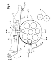
- the compensating lever 29 performs tilting movements around the Tilting bearing, which leads to a compensating upward or downward movement of the Guide arm 28. 1 shows a middle position, and FIG. 2 shows an end position.
- Movement gear 22 and differential gear 23 are geared together.
- the crank mechanism or the crank arm 24 is mounted on a transverse shaft 37.
- a gear 38 is located on this, which is connected to a further gear 39 combs on the transmission shaft 36 of the control disk 33.
- the transfer ratio the gears 38, 39 can be 1: 1. Movement gear 22 and differential gear 23 therefore run synchronously, because of common drive.
- the blank 10 to be removed in each case is in an end position by the conveyor roller 18 recorded (Fig. 3).
- the suction head 20 is the blank 10 or the blank magazine 14, 15 facing, in an end area, here in the area of the lid inside appending 13.
- the blank 10 is detected by negative pressure, namely through suction bores on the suction head 20.
- the conveyor roller 18, 19 By rotating the conveyor roller 18, 19 and superimposed (linear) Transverse movement, the blank 10 is placed on the circumference of the conveyor roller 18, 19.
- the rotary movement of the conveyor roller 18, 19 is by engagement of a toothed segment 41 Scope of the conveyor roller 18, 19 with a fixed rack 42 causes.
- a special feature is the control of suction air or negative pressure in the area of the suction head 20.
- the conveyor roller 18, 19 consists of two spaced apart Roller disks 43, 44.
- the suction head 20 is mounted between them, namely on one - two-armed - operating lever 45. This is shaped so that it between the Roller disks 43, 44 are curved and can be tilted about a pivot bearing 46.
- On One end of the operating lever 45 is the suction head 20 and one at the other end Actuator, namely a roller 47 attached. Inside the operating lever 45 runs a suction channel 48 to the suction head 20 or to the suction bores.
- the suction channel 48 is connected to a main channel 50 via a fixed connection channel 49, which runs within the axis of rotation of the conveyor roller 18, 19 and to a central one Vacuum source is connected.
- a sealing piece 51 is arranged on the actuating lever 45, which interacts with a counterpart in the area of the connecting channel 49.
- the sealing piece lies during the rolling process, that is to say the transport of a blank 10 51 on the counter seal so that the suction channel 48 is effective with the connection channel 49 is connected.
- a ventilation of the suction head 20 is effected, namely by pivoting the Actuating lever 45 (counterclockwise).
- this makes the suction head 20 withdrawn from the blank 10 and on the other hand the seal in the area of Sealing piece 51 or the connecting channel 49 is lifted by lifting off the sealing piece 51.
- the negative pressure in the area of the suction holes is eliminated.
- the operating lever 45 is synchronized with a actuated the drive of the conveyor roller 18, 19 movable actuator. These are around a swiveling - two-armed - pressure lever 52. This is at the free, the Conveyor roller 18, 19 facing end portion with a support member 53 on which the Roll 47 expires.
- the pressure lever 52 is brought into an effective position, by swiveling. This is due to the rotating crank mechanism controlled, namely by a cam 54 arranged on the shaft 37. This has a control groove 55 in which a feeler roller 56 of a lever 57 runs. The Lever 57 in turn actuates the pressure lever 52.
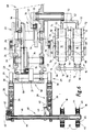
- Movement gear 22 and differential gear 23 are in a special way in one common gear housing 58 housed (Fig. 6).
- the crank mechanism namely the crank arm 24 and the strut 26 are outside of the gear housing 58 positioned.
- the (two) Struts 26 are also offset from the conveyor rollers 18, 19.
- two swivel arms 28 are arranged at an axial distance from one another provided, which are also offset from the conveyor rollers 18, 19.
- a compensation lever 29 is assigned to each of these swivel arms 28.
- the two Compensation levers 29 are connected to a common transverse shaft 59 - outside of the gear housing 58.
- On the cross shaft 59 is - within the gear housing 58 - arranged as a roller lever of the partial lever 31.
- At the end is the one already described Guide roller 35 mounted.
- the two balancing levers 29 are so of the common guide role 35 controllable.
- the (two) conveyor rollers 18, 19 are arranged at an axial distance from the gear, so that the cuts 10 can be handled in a free area.
- the Conveyor rollers 18, 19 are on a common transverse shaft, namely hollow shaft 61 stored.
- the two swivel arms 28 are connected to this.
- the tooth segment 41 is - together for both conveyor rollers 18, 19 - also on the hollow shaft 61 attached, in the area between the two pivot arms 28.
- the rack 42 is arranged in a correspondingly stationary manner.
- the hollow shaft 61 also serves to supply the conveyor rollers 18, 19 with suction air.
- suction lines 62, 63 On close one end of the conveyor rollers 18, 19 (two) suction lines 62, 63 to the hollow shaft 61. This is provided with two separate suction channels lead to one and the other conveyor roller 18, 19.
- a concentrically arranged suction tube 64 This leads in the area the outer conveyor roller 19 in the main channel 50, which in turn with the suction head 20 of the conveyor roller 19 is connected.
- An annular channel 65 surrounding the suction pipe 64 leads in a corresponding manner to the conveyor roller 18 or to its suction head 20.
- Another specialty is the two-lane mode of operation.
- the two cutting magazines 14, 15 are arranged at a short distance from one another, accordingly the distance of the subsequent cutting webs 17 from one another.
- the distance of the Cutting paths 17 in turn is determined by the distance between two pockets a folding turret for the simultaneous production or folding of two packs.
- EP 0 315 821 describes an example of this Transverse movement of the blanks 10 for one of the position of the pockets of the folding turret appropriate location avoided.
- the blanking magazines 14, 15 are equipped with special organs that facilitate the removal process easier for the individual cuts.
- a movable support member On the start side of the removal process, i.e. on the side of the inner flap of the lid 13 of the blank 10, a movable support member is arranged, namely a pivotable support lever 66, which has an angled nose 67 on the underside of the Cutting magazine 14, 15 arrives in the area of the cuts 10 and after supported at the bottom.
- the support lever 66 is removed from the support position moved out (Fig. 3). The movements are coordinated so that the Suction head 20 directly takes over the support function from the support lever 66.
- the support lever 66 returns to the support position (Fig. 4).
- Each blanking magazine 14, 15 is also assigned two support levers 66, specifically in the area of the lid inner tab 13.
- the support levers 66 are in one of the Dimension of this flap arranged corresponding distance from each other.
- the Support lever 66 of both blank magazines 14, 15 are on a common, synchronous Driven actuating shaft 73 arranged (Fig. 6).
- lateral support members Approximately in the middle area of the cutting magazines 14, 15 are further lateral support members arranged. These are side levers 68, 69. Two side levers 68, 69 are assigned to a blank magazine 14, 15. The side levers 68, 69 are each effective in the area of the side tabs 11 of the blanks 10 by means of projections are movable against the underside of the blanks 10. The side levers 68, 69 are each arranged on rotary rods 70. By turning them the side levers 68, 69 engaged or disengaged.
- support rollers 71, 72 are stationary, but rotatable.
- the support rollers 71, 72 are in the area of the outer Side tabs 12 on the respective lower blank 10, in an end region, so that the blanks 10 are pulled off the support rollers 71, 72.
Landscapes
- Engineering & Computer Science (AREA)
- Mechanical Engineering (AREA)
- Making Paper Articles (AREA)
- Supplying Of Containers To The Packaging Station (AREA)
- Wrapping Of Specific Fragile Articles (AREA)
- Specific Conveyance Elements (AREA)
Abstract
Description
- Fig. 1
- ein Entnahmeaggregat für die Übernahme von Zuschnitten aus einem Zuschnittmagazin in schematischer Seitenansicht,
- Fig. 2
- das Aggregat gemäß Fig. 1 bei veränderter Relativstellung von bewegbaren Organen,
- Fig. 3 bis Fig. 5
- unterschiedliche Positionen von Organen des Aggregats während der Entnahme eines Zuschnitts aus dem Zuschnittmagazin, in Seitenansicht,
- Fig. 6
- das Aggregat gemäß Fig. 1 in Draufsicht bzw. im Horizontalschnitt,
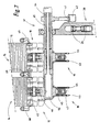
- Fig. 7
- einen Querschnitt durch das Aggregat gemäß Fig. 1 in einer annähernd aufrechten Schnittebene VII-VII der Fig. 1.
- 10
- Zuschnitt
- 11
- Seitenlappen
- 12
- Seitenlappen
- 13
- Deckel-Innenlappen
- 14
- Zuschnittmagazin
- 15
- Zuschnittmagazin
- 16
- Förderwalze
- 17
- Zuschnittbahn
- 18
- Förderrolle
- 19
- Förderrolle
- 20
- Saugkopf
- 22
- Bewegungsgetriebe
- 23
- Ausgleichsgetriebe
- 24
- Kurbelarm
- 26
- Strebe
- 27
- Ausgleichsstück
- 28
- Schwenkarm
- 29
- Ausgleichshebel
- 30
- Teilhebel
- 31
- Teilhebel
- 33
- Steuerscheibe
- 34
- Steuernut
- 35
- Führungsrolle
- 36
- Übertragungswelle
- 37
- Welle
- 38
- Zahnrad
- 39
- Zahnrad
- 41
- Zahnsegment
- 42
- Zahnstange
- 43
- Rollenscheibe
- 44
- Rollenscheibe
- 45
- Betätigungshebel
- 46
- Schwenklager
- 47
- Rolle
- 48
- Saugkanal
- 49
- Anschlusskanal
- 50
- Hauptkanal
- 51
- Dichtstück
- 52
- Druckhebel
- 53
- Stützteil
- 54
- Kurvenscheibe
- 55
- Steuemut
- 56
- Tastrolle
- 57
- Hebel
- 58
- Getriebegehäuse
- 59
- Querwelle
- 61
- Hohlwelle
- 62
- Saugleitung
- 63
- Saugleitung
- 64
- Saugrohr
- 65
- Ringkanal
- 66
- Stützhebel
- 67
- Nase
- 68
- Seitenhebel
- 69
- Seitenhebel
- 70
- Drehstange
- 71
- Stützrolle
- 72
- Stützrolle
- 73
- Betätigungswelle
Claims (13)
- Vorrichtung für die Handhabung von Zuschnitten (10) in einer Verpackungsmaschine, insbesondere für die Fertigung von Zigarettenpackungen des Typs Klappschachtel, mit mindestens einem Zuschnittmagazin (14, 15), dem die Zuschnitte (10) einzeln durch ein Entnahmeaggregat mit Förderrolle (18, 19) entnehmbar und einem Abförderer zuführbar sind, wobei die Förderrolle (18, 19) an einer offenen (unteren) Seite des Zuschnittmagazins (14, 15) hin- und herbewegbar ist und jeweils einen Zuschnitt (10) am Umfang mitführt, dadurch gekennzeichnet, dass die Förderrolle (18, 19) an einem Träger angebracht ist, insbesondere an einem Schwenkarm (28), der durch ein Getriebe derart hin- und herbewegbar, insbesondere schwenkbar ist, dass die Förderrolle (18, 19) entlang einer geradlinigen Bewegungsbahn hin- und herbewegt wird.
- Vorrichtung nach Anspruch 1, dadurch gekennzeichnet, dass der jeder Förderrolle (18, 19) zugeordnete Schwenkarm (28) durch ein Bewegungsgetriebe (22) hin- und herbewegbar und durch ein Ausgleichsgetriebe (23) hinsichtlich der Bewegungsrichtung entlang einer geradlinigen Bewegungsbahn steuerbar ist.
- Vorrichtung nach Anspruch 2, dadurch gekennzeichnet, dass das Bewegungsgetriebe (22) ein Kurbeltrieb ist mit umlaufendem Kurbelarm (24) und einer mit dem Schwenkarm (28) verbundenen Strebe (26) und dass das Ausgleichsgetriebe (23) einen mit dem Schwenkarm (28) verbundenen Ausgleichshebel (29) aufweist, der durch ein Steuerorgan steuerbar ist, insbesondere durch eine Steuernut (34), in der eine mit dem Ausgleichshebel (29) verbundene Führungsrolle (35) läuft.
- Vorrichtung nach Anspruch 3 oder einem der weiteren Ansprüche, dadurch gekennzeichnet, dass der Ausgleichshebel (29) als zweiarmiger Hebel ausgebildet ist mit einem festen Kipplager und dass das eine Ende des Ausgleichshebels (29) mit dem Schwenkarm (28) und das andere Ende mit der Führungsrolle (35) in der Steuernut (34) geführt ist.
- Vorrichtung nach Anspruch 2 oder einem der weiteren Ansprüche, dadurch gekennzeichnet, dass das Bewegungsgetriebe (22) und das Ausgleichsgetriebe (23) getrieblich miteinander verbunden sind, insbesondere über Zahnräder (38, 39).
- Vorrichtung nach Anspruch 2 oder einem der weiteren Ansprüche, dadurch gekennzeichnet, dass die Förderrolle (18, 19) versetzt zum Antrieb, nämlich zum Bewegungsgetriebe (22) und zum Ausgleichsgetriebe (23) auf einer Welle, insbesondere auf einer Hohlwelle (61) angeordnet ist und dass der Schwenkarm (28) versetzt zu der Förderrolle (18, 19) mit der Welle bzw. Hohlwelle (61) verbunden ist.
- Vorrichtung nach Anspruch 6 oder einem der weiteren Ansprüche, dadurch gekennzeichnet, dass der Förderrolle (18, 19) zwei im Abstand voneinander angeordnete Schwenkarme (28, 29) zugeordnet sind, wobei die Schwenkarme (28) mit der gemeinsamen Welle bzw. Hohlwelle (61) der Förderrolle (18, 19) verbunden und jedem Schwenkarm (28) ein Ausgleichshebel (29) und eine Strebe (26) zugeordnet sind.
- Vorrichtung nach Anspruch 1 oder einem der weiteren Ansprüche, dadurch gekennzeichnet, dass die Förderrolle (18, 19) einen Saugkopf (20) zum Erfassen eines Zuschnitts (10) aufweist und dass zum Saugkopf (20) ein mit einer Unterdruckquelle verbundener Saugkanal (48) führt, der über ein Betätigungsorgan, insbesondere einen Betätigungshebel (45), entlüftbar ist, wobei das Betätigungsorgan zur Entlüftung des Saugkanals (48) bzw. des Saugkopfes (20) auf ein verstellbares Betätigungsorgan aufläuft, insbesondere auf einen Druckhebel (52).
- Vorrichtung nach Anspruch 8 oder einem der weiteren Ansprüche, dadurch gekennzeichnet, dass der bogenförmig ausgebildete, zweiarmige Betätigungshebel (45) zwischen Rollenscheiben (43, 44) der Förderrolle (18, 19) schwenkbar gelagert ist, wobei an einem Ende des Betätigungshebels (45) der Saugkopf (20) und das andere Ende mit dem Druckhebel (52) zusammenwirkt.
- Vorrichtung nach Anspruch 6 oder einem der weiteren Ansprüche, dadurch gekennzeichnet, dass die Förderrolle (18, 19) durch ein Zahnsegment (41) in Verbindung mit einer Zahnstange (42) drehbar ist, wobei Zahnsegment (41) und Zahnstange (42) versetzt, mit axialem Abstand von der Förderrolle (18, 19) angeordnet und das Zahnsegment mit der Welle bzw. Hohlwelle (61) verbunden ist.
- Vorrichtung nach Anspruch 6 oder einem der weiteren Ansprüche, dadurch gekennzeichnet, dass die Hohlwelle (61) zur Versorgung der Saugköpfe (20) von zwei in Axialrichtung mit Abstand voneinander angeordneten Förderrollen (18, 19) dient, wobei ein konzentrisch innerhalb der Hohlwelle (61) angeordnetes Saugrohr (64) der einen, entfemtliegenden Förderrolle (18) und ein das Saugrohr (64) umgebender Ringkanal (65) der anderen Förderrolle (19) zugeordnet ist.
- Vorrichtung nach Anspruch 1 oder einem der weiteren Ansprüche, dadurch gekennzeichnet, dass für zweibahnige Betriebsweise zwei Zuschnittmagazine (14, 15) in einem Abstand voneinander angeordnet sind, der dem Abstand von zwei an die Zuschnittmagazine (14, 15) anschließenden Zuschnittbahnen (17) voneinander bzw. dem Abstand von zwei Taschen eines Faltrevolvers entspricht.
- Vorrichtung nach Anspruch 12, dadurch gekennzeichnet, dass jedem Zuschnittmagazin (14, 15) mindestens eine Förderrolle (18, 19) zugeordnet ist und dass alle Förderrollen (18, 19) auf einem gemeinsamen Träger, insbesondere auf der gemeinsamen (Hohl-)Welle (61) gelagert und durch diese bewegbar sind.
Applications Claiming Priority (2)
| Application Number | Priority Date | Filing Date | Title |
|---|---|---|---|
| DE10031098A DE10031098A1 (de) | 2000-06-30 | 2000-06-30 | Vorrichtung zur Handhabung von Zuschnitten in Verpackungsmaschinen |
| DE10031098 | 2000-06-30 |
Publications (3)
| Publication Number | Publication Date |
|---|---|
| EP1167008A2 true EP1167008A2 (de) | 2002-01-02 |
| EP1167008A3 EP1167008A3 (de) | 2003-01-02 |
| EP1167008B1 EP1167008B1 (de) | 2005-05-11 |
Family
ID=7646855
Family Applications (1)
| Application Number | Title | Priority Date | Filing Date |
|---|---|---|---|
| EP01113358A Expired - Lifetime EP1167008B1 (de) | 2000-06-30 | 2001-06-01 | Vorrichtung zum Zuführen von Packungszuschnitten |
Country Status (6)
| Country | Link |
|---|---|
| US (1) | US6502814B2 (de) |
| EP (1) | EP1167008B1 (de) |
| JP (1) | JP4638624B2 (de) |
| CN (1) | CN1232425C (de) |
| BR (1) | BR0102598B1 (de) |
| DE (2) | DE10031098A1 (de) |
Cited By (1)
| Publication number | Priority date | Publication date | Assignee | Title |
|---|---|---|---|---|
| EP2774882A2 (de) | 2013-03-06 | 2014-09-10 | Focke & Co. (GmbH & Co. KG) | Vorrichtung zur Entnahme von Zuschnitten aus einem Zuschnittmagazin |
Families Citing this family (5)
| Publication number | Priority date | Publication date | Assignee | Title |
|---|---|---|---|---|
| US7367445B2 (en) * | 2005-09-28 | 2008-05-06 | Mark Stanley Mazurek | Horizontal ratcheting case feeder mechanism |
| CN103624617A (zh) * | 2013-08-27 | 2014-03-12 | 苏州工业园区凯艺精密科技有限公司 | 隔离器腔体的侧板转移装置及隔离器腔体加工机 |
| CN108943838A (zh) * | 2018-09-28 | 2018-12-07 | 中科天工(武汉)智能技术有限公司 | 一种纸盒成型的面纸供送装置及方法 |
| DE102019130862B3 (de) * | 2019-11-15 | 2021-02-18 | Koenig & Bauer Ag | Bogenbearbeitungsmaschine und Verfahren zum Antreiben zumindest eines Werkzeugs einer Bogenbearbeitungsmaschine |
| CN115892573B (zh) * | 2022-11-18 | 2025-07-08 | 上海烟草机械有限责任公司 | 基于电子凸轮的双伺服式内框纸输送系统及柔性制造方法 |
Citations (3)
| Publication number | Priority date | Publication date | Assignee | Title |
|---|---|---|---|---|
| US1039521A (en) | 1909-09-30 | 1912-09-24 | Harry B Green | Sheet separating, registering, and feeding apparatus. |
| US5314178A (en) | 1992-11-16 | 1994-05-24 | Ark, Inc. | Automatic feeder for workpieces of limp material |
| GB2340825A (en) | 1998-08-19 | 2000-03-01 | Heidelberger Druckmasch Ag | Signature feed |
Family Cites Families (11)
| Publication number | Priority date | Publication date | Assignee | Title |
|---|---|---|---|---|
| US769747A (en) * | 1903-12-15 | 1904-09-13 | James W Hoag | Apparatus for feeding separate sheets of paper to printing-presses. |
| BE794145A (fr) * | 1972-10-20 | 1973-05-16 | Rotaprint Gmbh | Dispositif pour prelever et ransmettre des decoupes en forme de feuille empilees |
| US4021293A (en) * | 1975-11-07 | 1977-05-03 | Stackpole Machinery Company | High speed labeling machine |
| DE3328322A1 (de) * | 1983-08-05 | 1985-02-21 | Maschinenfabrik Alfred Schmermund Gmbh & Co, 5820 Gevelsberg | Vorrichtung zum zufuehren von zuschnitten zu einer verpackungsstation |
| DE3738102C2 (de) * | 1987-11-10 | 2001-09-06 | Focke & Co | Vorrichtung zum Zuführen von Zuschnitten zu einem Verpackungsaggregat |
| DE3808651C2 (de) * | 1988-03-15 | 1997-12-04 | Hoerauf Michael Maschf | Vorrichtung zum Ergreifen und Vereinzeln des unteren Zuschnittes eines Stapels von Zuschnitten aus kaschiertem Papier o. dgl., insbesondere für eine Buchdeckenmaschine |
| DE3823705A1 (de) * | 1988-07-13 | 1990-01-18 | Schmermund Maschf Alfred | Vorrichtung zum vereinzeln von zuschnitten aus einem stapel |
| DE3905214A1 (de) * | 1989-02-21 | 1990-08-23 | Focke & Co | Verfahren und vorrichtung zur entnahme von (packungs-)zuschnitten aus einem zuschnitt-magazin |
| DE4234377A1 (de) * | 1992-10-13 | 1994-04-14 | Focke & Co | Vorrichtung zum Speichern und Entnehmen von Zuschnitten |
| DE4334745C5 (de) * | 1993-10-12 | 2007-09-20 | Focke & Co.(Gmbh & Co. Kg) | Vorrichtung zum Auftragen von Leim |
| JPH07315600A (ja) * | 1994-05-25 | 1995-12-05 | Shinko Kikai Seisakusho:Kk | 枚葉加工機における枚葉シートの供給装置 |
-
2000
- 2000-06-30 DE DE10031098A patent/DE10031098A1/de not_active Withdrawn
-
2001
- 2001-06-01 EP EP01113358A patent/EP1167008B1/de not_active Expired - Lifetime
- 2001-06-01 DE DE50106170T patent/DE50106170D1/de not_active Expired - Lifetime
- 2001-06-26 US US09/892,111 patent/US6502814B2/en not_active Expired - Fee Related
- 2001-06-29 BR BRPI0102598-8A patent/BR0102598B1/pt not_active IP Right Cessation
- 2001-06-29 JP JP2001199017A patent/JP4638624B2/ja not_active Expired - Fee Related
- 2001-06-29 CN CNB011218622A patent/CN1232425C/zh not_active Expired - Fee Related
Patent Citations (3)
| Publication number | Priority date | Publication date | Assignee | Title |
|---|---|---|---|---|
| US1039521A (en) | 1909-09-30 | 1912-09-24 | Harry B Green | Sheet separating, registering, and feeding apparatus. |
| US5314178A (en) | 1992-11-16 | 1994-05-24 | Ark, Inc. | Automatic feeder for workpieces of limp material |
| GB2340825A (en) | 1998-08-19 | 2000-03-01 | Heidelberger Druckmasch Ag | Signature feed |
Cited By (3)
| Publication number | Priority date | Publication date | Assignee | Title |
|---|---|---|---|---|
| EP2774882A2 (de) | 2013-03-06 | 2014-09-10 | Focke & Co. (GmbH & Co. KG) | Vorrichtung zur Entnahme von Zuschnitten aus einem Zuschnittmagazin |
| DE102013003758A1 (de) | 2013-03-06 | 2014-09-11 | Focke & Co. (Gmbh & Co. Kg) | Vorrichtung zur Entnahme von Zuschnitten aus einem Zuschnittmagazin |
| EP2774882A3 (de) * | 2013-03-06 | 2018-01-31 | Focke & Co. (GmbH & Co. KG) | Vorrichtung zur Entnahme von Zuschnitten aus einem Zuschnittmagazin |
Also Published As
| Publication number | Publication date |
|---|---|
| CN1330022A (zh) | 2002-01-09 |
| CN1232425C (zh) | 2005-12-21 |
| BR0102598B1 (pt) | 2008-11-18 |
| US6502814B2 (en) | 2003-01-07 |
| EP1167008B1 (de) | 2005-05-11 |
| DE50106170D1 (de) | 2005-06-16 |
| JP2002046195A (ja) | 2002-02-12 |
| EP1167008A3 (de) | 2003-01-02 |
| US20020000690A1 (en) | 2002-01-03 |
| DE10031098A1 (de) | 2002-01-10 |
| BR0102598A (pt) | 2002-02-19 |
| JP4638624B2 (ja) | 2011-02-23 |
Similar Documents
| Publication | Publication Date | Title |
|---|---|---|
| EP2700599B1 (de) | Vorrichtung und Verfahren zum Abtrennen von einzelnen, flachen, biegbaren Gegenständen von der Unterseite eines Stapels | |
| DE1139513B (de) | Vorrichtung zum Vereinzeln von gestapelten Zuschnitten aus Karton od. dgl. | |
| DE19548840A1 (de) | Strecke zum Doublieren und Verstrecken von Faserbändern | |
| EP0150511A2 (de) | Vorrichtung zum Verpacken von Gegenständen, insbesondere Zigaretten | |
| EP1167008A2 (de) | Vorrichtung zum Zuführen von Packungszuschnitten | |
| DE3153367C2 (de) | ||
| DE60104936T2 (de) | Vorrichtung zur Ausgabe von gedruckten Papierbögen oder dergleichen in aufeinanderfolgenden Stapeln | |
| DE4445108C2 (de) | Umsetzvorrichtung für Güter, insbesondere Dosen | |
| EP2774882B1 (de) | Vorrichtung zur Entnahme von Zuschnitten aus einem Zuschnittmagazin | |
| DE3637182A1 (de) | Rotierender anleger fuer zuschnitte | |
| DE3439908A1 (de) | Maschinen zum auffalten von kartons aus ebenen zuschnitten | |
| EP0365847B1 (de) | Auslagebogenbremse für Bogendruckmaschinen | |
| DE4206467A1 (de) | Drehstation | |
| DE3910519A1 (de) | Foerdereinrichtung | |
| DE965384C (de) | Etikettiermaschine fuer aufrechtstehende Gegenstaende | |
| DE2606391A1 (de) | Transportbahn, insbesondere an maschinen zum herstellen von papiersaecken | |
| DE10135846B4 (de) | Schneidmaschine | |
| DE69801153T2 (de) | Vorrichtung zum zuführen eines filmes zu einer maschine zum verpacken von gegenständen | |
| DE721592C (de) | Foerdervorrichtung mit Vorschiebern, insbesondere fuer einzuwickelnde Stapel flacher Gegenstaende | |
| DE1291663B (de) | Kannenwechselvorrichtung an Spinnerei-Vorbereitungsmaschinen | |
| EP4420846B1 (de) | Produktführung mit traktionsrolle | |
| EP0054890A1 (de) | Werkstückförderer, insbesondere für Kleinteile | |
| DE1078034B (de) | Vorrichtung zum absatzweise erfolgenden Abtrennen von Formabschnitten von Bandmaterial | |
| DE3337365C2 (de) | Kunststoffolienwickler mit fliegendem Rollenwechsel | |
| CH441088A (de) | Zigarrenmaschine mit automatischer Deckblattzuführung |
Legal Events
| Date | Code | Title | Description |
|---|---|---|---|
| PUAI | Public reference made under article 153(3) epc to a published international application that has entered the european phase |
Free format text: ORIGINAL CODE: 0009012 |
|
| AK | Designated contracting states |
Kind code of ref document: A2 Designated state(s): AT BE CH CY DE DK ES FI FR GB GR IE IT LI LU MC NL PT SE TR |
|
| AX | Request for extension of the european patent |
Free format text: AL;LT;LV;MK;RO;SI |
|
| PUAL | Search report despatched |
Free format text: ORIGINAL CODE: 0009013 |
|
| AK | Designated contracting states |
Kind code of ref document: A3 Designated state(s): AT BE CH CY DE DK ES FI FR GB GR IE IT LI LU MC NL PT SE TR |
|
| AX | Request for extension of the european patent |
Free format text: AL;LT;LV;MK;RO;SI |
|
| RIC1 | Information provided on ipc code assigned before grant |
Free format text: 7B 31B 1/06 A, 7B 65H 3/08 B |
|
| 17P | Request for examination filed |
Effective date: 20030512 |
|
| AKX | Designation fees paid |
Designated state(s): CH DE FR GB IT LI NL |
|
| 17Q | First examination report despatched |
Effective date: 20031218 |
|
| TPAC | Observations filed by third parties |
Free format text: ORIGINAL CODE: EPIDOSNTIPA |
|
| GRAP | Despatch of communication of intention to grant a patent |
Free format text: ORIGINAL CODE: EPIDOSNIGR1 |
|
| RAP1 | Party data changed (applicant data changed or rights of an application transferred) |
Owner name: FOCKE & CO. (GMBH & CO. KG) |
|
| GRAS | Grant fee paid |
Free format text: ORIGINAL CODE: EPIDOSNIGR3 |
|
| GRAA | (expected) grant |
Free format text: ORIGINAL CODE: 0009210 |
|
| AK | Designated contracting states |
Kind code of ref document: B1 Designated state(s): CH DE FR GB IT LI NL |
|
| REG | Reference to a national code |
Ref country code: GB Ref legal event code: FG4D Free format text: NOT ENGLISH |
|
| REG | Reference to a national code |
Ref country code: CH Ref legal event code: EP |
|
| REG | Reference to a national code |
Ref country code: IE Ref legal event code: FG4D Free format text: LANGUAGE OF EP DOCUMENT: GERMAN |
|
| REF | Corresponds to: |
Ref document number: 50106170 Country of ref document: DE Date of ref document: 20050616 Kind code of ref document: P |
|
| GBT | Gb: translation of ep patent filed (gb section 77(6)(a)/1977) |
Effective date: 20050621 |
|
| REG | Reference to a national code |
Ref country code: CH Ref legal event code: NV Representative=s name: R. A. EGLI & CO. PATENTANWAELTE |
|
| PLBE | No opposition filed within time limit |
Free format text: ORIGINAL CODE: 0009261 |
|
| STAA | Information on the status of an ep patent application or granted ep patent |
Free format text: STATUS: NO OPPOSITION FILED WITHIN TIME LIMIT |
|
| ET | Fr: translation filed | ||
| 26N | No opposition filed |
Effective date: 20060214 |
|
| PGFP | Annual fee paid to national office [announced via postgrant information from national office to epo] |
Ref country code: CH Payment date: 20130612 Year of fee payment: 13 |
|
| PGFP | Annual fee paid to national office [announced via postgrant information from national office to epo] |
Ref country code: FR Payment date: 20130624 Year of fee payment: 13 Ref country code: NL Payment date: 20130608 Year of fee payment: 13 |
|
| REG | Reference to a national code |
Ref country code: NL Ref legal event code: V1 Effective date: 20150101 |
|
| REG | Reference to a national code |
Ref country code: CH Ref legal event code: PL |
|
| REG | Reference to a national code |
Ref country code: FR Ref legal event code: ST Effective date: 20150227 |
|
| PG25 | Lapsed in a contracting state [announced via postgrant information from national office to epo] |
Ref country code: NL Free format text: LAPSE BECAUSE OF NON-PAYMENT OF DUE FEES Effective date: 20150101 |
|
| PG25 | Lapsed in a contracting state [announced via postgrant information from national office to epo] |
Ref country code: CH Free format text: LAPSE BECAUSE OF NON-PAYMENT OF DUE FEES Effective date: 20140630 Ref country code: LI Free format text: LAPSE BECAUSE OF NON-PAYMENT OF DUE FEES Effective date: 20140630 |
|
| PG25 | Lapsed in a contracting state [announced via postgrant information from national office to epo] |
Ref country code: FR Free format text: LAPSE BECAUSE OF NON-PAYMENT OF DUE FEES Effective date: 20140630 |
|
| PGFP | Annual fee paid to national office [announced via postgrant information from national office to epo] |
Ref country code: GB Payment date: 20150527 Year of fee payment: 15 |
|
| PGFP | Annual fee paid to national office [announced via postgrant information from national office to epo] |
Ref country code: IT Payment date: 20150625 Year of fee payment: 15 |
|
| REG | Reference to a national code |
Ref country code: DE Ref legal event code: R079 Ref document number: 50106170 Country of ref document: DE Free format text: PREVIOUS MAIN CLASS: B31B0001060000 Ipc: B31B0050060000 |
|
| GBPC | Gb: european patent ceased through non-payment of renewal fee |
Effective date: 20160601 |
|
| PG25 | Lapsed in a contracting state [announced via postgrant information from national office to epo] |
Ref country code: GB Free format text: LAPSE BECAUSE OF NON-PAYMENT OF DUE FEES Effective date: 20160601 |
|
| PG25 | Lapsed in a contracting state [announced via postgrant information from national office to epo] |
Ref country code: IT Free format text: LAPSE BECAUSE OF NON-PAYMENT OF DUE FEES Effective date: 20160601 |
|
| PGFP | Annual fee paid to national office [announced via postgrant information from national office to epo] |
Ref country code: DE Payment date: 20170629 Year of fee payment: 17 |
|
| REG | Reference to a national code |
Ref country code: DE Ref legal event code: R119 Ref document number: 50106170 Country of ref document: DE |
|
| PG25 | Lapsed in a contracting state [announced via postgrant information from national office to epo] |
Ref country code: DE Free format text: LAPSE BECAUSE OF NON-PAYMENT OF DUE FEES Effective date: 20190101 |