EP1167143B1 - Procédé et appareil pour la détection d'un freinage de panique - Google Patents
Procédé et appareil pour la détection d'un freinage de panique Download PDFInfo
- Publication number
- EP1167143B1 EP1167143B1 EP01113777A EP01113777A EP1167143B1 EP 1167143 B1 EP1167143 B1 EP 1167143B1 EP 01113777 A EP01113777 A EP 01113777A EP 01113777 A EP01113777 A EP 01113777A EP 1167143 B1 EP1167143 B1 EP 1167143B1
- Authority
- EP
- European Patent Office
- Prior art keywords
- rotational speed
- value
- wheels
- detected
- emergency braking
- Prior art date
- Legal status (The legal status is an assumption and is not a legal conclusion. Google has not performed a legal analysis and makes no representation as to the accuracy of the status listed.)
- Expired - Lifetime
Links
- 238000001514 detection method Methods 0.000 title claims description 13
- 238000000034 method Methods 0.000 title claims description 12
- 230000008859 change Effects 0.000 claims description 22
- 230000004913 activation Effects 0.000 claims 2
- 230000001133 acceleration Effects 0.000 description 8
- 238000011156 evaluation Methods 0.000 description 3
- 230000008901 benefit Effects 0.000 description 2
- 230000000694 effects Effects 0.000 description 2
- 230000004044 response Effects 0.000 description 2
- 230000002123 temporal effect Effects 0.000 description 2
- 238000012935 Averaging Methods 0.000 description 1
- 230000000903 blocking effect Effects 0.000 description 1
- 230000001419 dependent effect Effects 0.000 description 1
- 230000006872 improvement Effects 0.000 description 1
- 230000008569 process Effects 0.000 description 1
- 230000009467 reduction Effects 0.000 description 1
Images
Classifications
-
- B—PERFORMING OPERATIONS; TRANSPORTING
- B60—VEHICLES IN GENERAL
- B60T—VEHICLE BRAKE CONTROL SYSTEMS OR PARTS THEREOF; BRAKE CONTROL SYSTEMS OR PARTS THEREOF, IN GENERAL; ARRANGEMENT OF BRAKING ELEMENTS ON VEHICLES IN GENERAL; PORTABLE DEVICES FOR PREVENTING UNWANTED MOVEMENT OF VEHICLES; VEHICLE MODIFICATIONS TO FACILITATE COOLING OF BRAKES
- B60T8/00—Arrangements for adjusting wheel-braking force to meet varying vehicular or ground-surface conditions, e.g. limiting or varying distribution of braking force
- B60T8/32—Arrangements for adjusting wheel-braking force to meet varying vehicular or ground-surface conditions, e.g. limiting or varying distribution of braking force responsive to a speed condition, e.g. acceleration or deceleration
- B60T8/321—Arrangements for adjusting wheel-braking force to meet varying vehicular or ground-surface conditions, e.g. limiting or varying distribution of braking force responsive to a speed condition, e.g. acceleration or deceleration deceleration
- B60T8/3255—Systems in which the braking action is dependent on brake pedal data
- B60T8/3275—Systems with a braking assistant function, i.e. automatic full braking initiation in dependence of brake pedal velocity
-
- B—PERFORMING OPERATIONS; TRANSPORTING
- B60—VEHICLES IN GENERAL
- B60T—VEHICLE BRAKE CONTROL SYSTEMS OR PARTS THEREOF; BRAKE CONTROL SYSTEMS OR PARTS THEREOF, IN GENERAL; ARRANGEMENT OF BRAKING ELEMENTS ON VEHICLES IN GENERAL; PORTABLE DEVICES FOR PREVENTING UNWANTED MOVEMENT OF VEHICLES; VEHICLE MODIFICATIONS TO FACILITATE COOLING OF BRAKES
- B60T7/00—Brake-action initiating means
- B60T7/12—Brake-action initiating means for automatic initiation; for initiation not subject to will of driver or passenger
-
- B—PERFORMING OPERATIONS; TRANSPORTING
- B60—VEHICLES IN GENERAL
- B60T—VEHICLE BRAKE CONTROL SYSTEMS OR PARTS THEREOF; BRAKE CONTROL SYSTEMS OR PARTS THEREOF, IN GENERAL; ARRANGEMENT OF BRAKING ELEMENTS ON VEHICLES IN GENERAL; PORTABLE DEVICES FOR PREVENTING UNWANTED MOVEMENT OF VEHICLES; VEHICLE MODIFICATIONS TO FACILITATE COOLING OF BRAKES
- B60T8/00—Arrangements for adjusting wheel-braking force to meet varying vehicular or ground-surface conditions, e.g. limiting or varying distribution of braking force
- B60T8/32—Arrangements for adjusting wheel-braking force to meet varying vehicular or ground-surface conditions, e.g. limiting or varying distribution of braking force responsive to a speed condition, e.g. acceleration or deceleration
- B60T8/88—Arrangements for adjusting wheel-braking force to meet varying vehicular or ground-surface conditions, e.g. limiting or varying distribution of braking force responsive to a speed condition, e.g. acceleration or deceleration with failure responsive means, i.e. means for detecting and indicating faulty operation of the speed responsive control means
- B60T8/885—Arrangements for adjusting wheel-braking force to meet varying vehicular or ground-surface conditions, e.g. limiting or varying distribution of braking force responsive to a speed condition, e.g. acceleration or deceleration with failure responsive means, i.e. means for detecting and indicating faulty operation of the speed responsive control means using electrical circuitry
-
- B—PERFORMING OPERATIONS; TRANSPORTING
- B60—VEHICLES IN GENERAL
- B60T—VEHICLE BRAKE CONTROL SYSTEMS OR PARTS THEREOF; BRAKE CONTROL SYSTEMS OR PARTS THEREOF, IN GENERAL; ARRANGEMENT OF BRAKING ELEMENTS ON VEHICLES IN GENERAL; PORTABLE DEVICES FOR PREVENTING UNWANTED MOVEMENT OF VEHICLES; VEHICLE MODIFICATIONS TO FACILITATE COOLING OF BRAKES
- B60T2201/00—Particular use of vehicle brake systems; Special systems using also the brakes; Special software modules within the brake system controller
- B60T2201/03—Brake assistants
-
- B—PERFORMING OPERATIONS; TRANSPORTING
- B60—VEHICLES IN GENERAL
- B60T—VEHICLE BRAKE CONTROL SYSTEMS OR PARTS THEREOF; BRAKE CONTROL SYSTEMS OR PARTS THEREOF, IN GENERAL; ARRANGEMENT OF BRAKING ELEMENTS ON VEHICLES IN GENERAL; PORTABLE DEVICES FOR PREVENTING UNWANTED MOVEMENT OF VEHICLES; VEHICLE MODIFICATIONS TO FACILITATE COOLING OF BRAKES
- B60T2270/00—Further aspects of brake control systems not otherwise provided for
- B60T2270/40—Failsafe aspects of brake control systems
- B60T2270/413—Plausibility monitoring, cross check, redundancy
-
- B—PERFORMING OPERATIONS; TRANSPORTING
- B60—VEHICLES IN GENERAL
- B60T—VEHICLE BRAKE CONTROL SYSTEMS OR PARTS THEREOF; BRAKE CONTROL SYSTEMS OR PARTS THEREOF, IN GENERAL; ARRANGEMENT OF BRAKING ELEMENTS ON VEHICLES IN GENERAL; PORTABLE DEVICES FOR PREVENTING UNWANTED MOVEMENT OF VEHICLES; VEHICLE MODIFICATIONS TO FACILITATE COOLING OF BRAKES
- B60T2270/00—Further aspects of brake control systems not otherwise provided for
- B60T2270/40—Failsafe aspects of brake control systems
- B60T2270/416—Wheel speed sensor failure
-
- Y—GENERAL TAGGING OF NEW TECHNOLOGICAL DEVELOPMENTS; GENERAL TAGGING OF CROSS-SECTIONAL TECHNOLOGIES SPANNING OVER SEVERAL SECTIONS OF THE IPC; TECHNICAL SUBJECTS COVERED BY FORMER USPC CROSS-REFERENCE ART COLLECTIONS [XRACs] AND DIGESTS
- Y10—TECHNICAL SUBJECTS COVERED BY FORMER USPC
- Y10S—TECHNICAL SUBJECTS COVERED BY FORMER USPC CROSS-REFERENCE ART COLLECTIONS [XRACs] AND DIGESTS
- Y10S188/00—Brakes
- Y10S188/01—Panic braking
Definitions
- the invention relates to a method and a device for detecting a panic braking with the features of the independent claims.
- Panic braking is generally understood to mean that the driver of the vehicle operates the brake pedal quickly and heavily.
- Systems for detecting panic braking are known from the prior art.
- a controller for a brake system is known in which braking force is applied to the wheel brakes beyond the actual driver specification in certain operating situations which are detected on the basis of the driver's braking request.
- One of these operating situations is a situation in which the reaction of the driver to a dangerous situation can be concluded (panic braking).
- panic braking the way the driver actuates the brake actuator is evaluated. If it actuates the element very quickly, which is detected, for example, by the change in the admission pressure of the brake system, pressure is built up beyond the driver's specification.
- Threshold trip threshold
- the triggering threshold is changed on the basis of predetermined operating variables, wherein the triggering threshold is lowered, that is, the triggering of the increased braking force build-up is made more sensitive as the potential danger increases.
- operating variables are called the form of the brake system, the vehicle speed, theharimetrate, the lateral acceleration of the vehicle, the longitudinal acceleration of the vehicle, the steering angle change, the output engine power and / or the brake pressure requirement of a vehicle dynamics controller.
- Such known from the prior art systems require to detect a panic braking a relatively complex and therefore expensive additional sensors such as brake pedal travel sensors, longitudinal acceleration sensors or yaw rate sensors.
- the invention has the advantage that no more expensive and expensive additional sensors is necessary for more reliable detection of panic braking; it suffice anyway provided with anti-lock control systems, traction control systems and / or driving stability systems wheel speed sensors.
- the use of panic detection is thus also possible in so-called low-cost brake systems.
- a warning of subsequent traffic is possible.
- a warning of subsequent traffic is possible.
- ACC systems A utomatic C ruise C ontrol
- the brake pressure at the rear wheels is limited in response to a recognized panic braking. This limit can be maintained until an anti-skid control and / or a brake force distribution control is activated at the rear wheels or a predeterminable second time period is exceeded or falls below a predefinable minimum vehicle deceleration becomes.
- the rotational speed variable of one of the wheels is selected such that the speed variable of the wheel having the lowest rotational speed is selected as the selected rotational speed variable. It is therefore used as reference wheel, the slowest wheel.
- the speed value can be determined by a, possibly weighted, averaging of the speed variables of at least two wheels.
- the rotational speed variables are checked for errors and the rotational speed variables of the wheels on which an error has been detected are excluded from the selection of the rotational speed variable and / or from the determination of the rotational speed value.
- the operation of the brake pedal are detected by a brake signal. This can be done for example by the brake light switch.
- a panic braking is detected only when the brake signal indicates an actuation of the brake pedal.
- a deceleration quantity representing the deceleration of the entire vehicle is determined.
- panic braking is detected only when the delay quantity increases in the course of time.
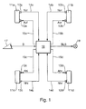
- FIG. 1 schematically shows the braking system of a vehicle.
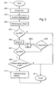
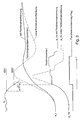
- the FIG. 2 represents the embodiment with reference to a Flowchart, while in the FIG. 3 temporal courses are to be seen.
- FIG. 1 shows by the reference numeral 11a-d four wheels of a two-axle vehicle, each wheel has a designated by the reference numeral 12a-d wheel speed sensor.
- the wheel speeds Nij are supplied to the evaluation unit 16.
- Each wheel 11a-d is assigned wheel brakes 13a-d whose braking force or braking effect is controlled by the evaluation unit 16 through the lines 15a-d. Serve for this purpose, the drive signals Aij.
- the reference numeral 17 the operable by the driver brake pedal is shown.
- the position of the brake pedal 17 is detected and fed to the evaluation unit 16 as a signal B. If there is a braking operation, the brake lights 18 are activated by the signal BLS.
- FIG. 2 is a flowchart to see.
- the wheel speeds Nij are read in step 202.
- a reference wheel is selected.
- the slowest wheel in each case is outside an anti-skid control of the vehicle selected. Wheels with speed sensor errors, plausibility errors, interference or standing wheels are not taken into account when selecting the slowest wheel.
- the safety logic generally used in anti-lock systems can be used.
- the panic brake detection is not activated when detected poor road or lane thresholds, where a similar wheel path as in a panic braking can come about. When Badwegerkennung can also be used on a usually present in the anti-lock brake Badwegkennung.
- the speed selection can be limited to the non-drive axle.
- the delay thus obtained can be PT1-filtered.
- the filter time parameter can be applied here.
- step 205 the (possibly filtered) wheel acceleration a b is compared with the threshold value SW1.
- the value a b of the wheel acceleration is negative (wheel deceleration).
- threshold SW1 Delay Trigger Threshold
- the time counter .DELTA.T is started in step 206.
- step 208 If within the applicable time window ⁇ T (for example, 50 ms, step 208), the second threshold value SW2 (for example -3m / s 2 ) is also undershot (step 207), then the process proceeds to step 209. In step 208a, the wheel acceleration a b is updated. If the vehicle deceleration threshold SW2 [eg -3m / s 2 ] is not reached or only after the expiry of the time window ⁇ T (eg 50 ms), the end step 211 is entered.
- ⁇ T for example, 50 ms
- step 209 other conditions may be checked before panic braking is detected in step 210.
- additional plausibility checks may occur, such as whether the brake light switch (BLS signal) is actuated (driver is on the brake) and / or the overall vehicle deceleration also increases from program cycle to program cycle.
- BLS signal brake light switch
- the panic brake detection flag is set (step 210).
- step 210 an adjustable, for example very flat, pulse series for limiting the wheel pressure gradient (valve actuation ABS hydraulic) is started at the wheel brakes of the rear axle (see wheel pressure curve in FIG. 3 ).
- This gradient limitation runs until an ABS regulation or an EBV control (electric brake force distribution) takes over the pressure modulation on the rear axle, or until a minimum vehicle deceleration (eg -2m / s 2 ) has been reached or a maximum setup time eg (200 ms) has been exceeded ,
- the panic braking can be displayed to the following traffic for an applicable time, for example by the hazard warning system being activated.
Landscapes
- Engineering & Computer Science (AREA)
- Transportation (AREA)
- Mechanical Engineering (AREA)
- Regulating Braking Force (AREA)
Claims (9)
- Procédé de détection d'un freinage d'urgence sur un véhicule automobile qui présente au moins deux roues, dans lequel- des grandeurs (Nij) de vitesse de rotation qui représentent la vitesse de rotation d'au moins deux roues sont détectées,- la grandeur (Nb) de vitesse de rotation de l'une des roues est sélectionnée et/ou une valeur de vitesse de rotation est déterminée à partir des grandeurs de vitesse de rotation,- une valeur de modification (ab) qui représente la variation temporelle de la grandeur de vitesse de rotation sélectionnée et/ou de la valeur de vitesse de rotation est déterminée,- l'évolution temporelle de la valeur de modification est déterminée,- un freinage d'urgence est détecté en fonction de l'évolution temporelle de la valeur de modification (ab),- la valeur de modification (ab) est comparée à une première valeur de seuil (SW1),caractérisé en ce que- un freinage d'urgence est détecté si à l'intérieur d'une première durée prédéterminée (ΔT) qui suit la descente en dessous de la première valeur de seuil, la valeur de modification (ab) n'atteint plus une deuxième valeur de seuil (SW2), la première valeur de seuil (SW1) étant supérieure à la deuxième valeur de seuil (SW2) .
- Procédé selon la revendication 1, caractérisé en ce que la grandeur de vitesse de rotation de l'une des roues est sélectionnée
en sélectionnant comme grandeur sélectionnée de vitesse de rotation (Nb) la grandeur de vitesse de rotation de la roue qui présente la plus basse vitesse de rotation et/ou
en déterminant la valeur de vitesse de rotation par formation de la valeur moyenne des grandeurs de vitesse de rotation d'au moins deux roues. - Procédé selon la revendication 1, caractérisé en ce qu'il vérifie la présence d'erreurs sur les grandeurs de vitesse de rotation et en ce que les vitesses de grandeur de rotation des roues sur lesquelles une erreur a été détectée sont exclues de la sélection de la grandeur de vitesse de rotation et/ou de la détermination de la valeur de vitesse de rotation.
- Procédé selon la revendication 1, caractérisé en ce qu'il détecte si le véhicule circule sur une chaussée qui présente des irrégularités d'ampleur prédéterminée et en ce que la détection du freinage d'urgence est désactivée s'il est détecté que le véhicule circule sur une telle chaussée.
- Procédé selon la revendication 1, caractérisé en ce que le véhicule présente un moteur, en ce qu'au moins une roue est entraînée par le moteur et en ce que seules les roues non entraînées sont utilisées pour sélectionner la grandeur de vitesse de roue sélectionnée (Nb) et/ou pour déterminer la valeur de vitesse de roue.
- Procédé selon la revendication 1, caractérisé en ce que- le véhicule présente une pédale de frein apte à être actionnée par le conducteur, un signal de freinage (BLS) qui représente l'actionnement de la pédale de frein étant détecté et un freinage d'urgence étant détecté uniquement si le signal de freinage indique un actionnement de la pédale de frein et/ou- une grandeur de ralentissement qui représente le ralentissement de l'ensemble du véhicule est déterminée et le freinage d'urgence est détecté uniquement si l'évolution temporelle de la grandeur de ralentissement présente une augmentation.
- Procédé selon la revendication 1, caractérisé en ce qu'en réaction à la détection d'un freinage d'urgence- une installation de clignotant d'urgence prévue dans le véhicule est activée et/ou- la pression de freinage sur les roues arrière est limitée, en prévoyant en particulier- de maintenir cette limitation tant qu'une régulation anti-blocage et/ou une régulation de la répartition de la force de freinage sont activées sur les roues arrière ou- une deuxième durée prédéterminée est dépassée ou- un ralentissement minimum prédéterminé du véhicule n'est pas atteint.
- Dispositif de détection d'un freinage d'urgence sur un véhicule automobile doté d'au moins deux roues, qui présente des moyens (16) au moyen desquels :- des grandeurs (Nij) de vitesse de rotation qui représentent la vitesse de rotation d'au moins deux roues sont détectées,- la grandeur (Nb) de vitesse de rotation de l'une des roues est sélectionnée et/ou une valeur de vitesse de rotation est déterminée à partir des grandeurs de vitesse de rotation,- une valeur de modification (ab) qui représente la variation temporelle de la grandeur de vitesse de rotation sélectionnée et/ou de la valeur de vitesse de rotation est déterminée,- l'évolution temporelle de la valeur de modification est déterminée,- un freinage d'urgence est détecté en fonction de l'évolution temporelle de la valeur de modification (ab) ,- la valeur de modification (ab) est comparée à une première valeur de seuil (SW1),caractérisé en ce que- un freinage d'urgence est détecté si à l'intérieur d'une première durée prédéterminée (ΔT) qui suit la descente en dessous de la première valeur de seuil, la valeur de modification (ab) n'atteint plus une deuxième valeur de seuil (SW2), la première valeur de seuil (SW1) étant supérieure à la deuxième valeur de seuil (SW2).
- Dispositif selon la revendication 8, caractérisé en ce que la grandeur de vitesse de rotation de l'une des roues est sélectionnée
en sélectionnant comme grandeur sélectionnée de vitesse de rotation (Nb) la grandeur de vitesse de rotation de la roue qui présente la plus basse vitesse de rotation et/ou
en déterminant la valeur de vitesse de rotation par formation de la valeur moyenne des grandeurs de vitesse de rotation d'au moins deux roues.
Applications Claiming Priority (4)
| Application Number | Priority Date | Filing Date | Title |
|---|---|---|---|
| DE10031125 | 2000-06-30 | ||
| DE10031125 | 2000-06-30 | ||
| DE10044121 | 2000-09-07 | ||
| DE10044121A DE10044121A1 (de) | 2000-06-30 | 2000-09-07 | Verfahren und Vorrichtung zur Erkennung einer Panikbremsung |
Publications (3)
| Publication Number | Publication Date |
|---|---|
| EP1167143A2 EP1167143A2 (fr) | 2002-01-02 |
| EP1167143A3 EP1167143A3 (fr) | 2002-10-02 |
| EP1167143B1 true EP1167143B1 (fr) | 2010-12-01 |
Family
ID=26006204
Family Applications (1)
| Application Number | Title | Priority Date | Filing Date |
|---|---|---|---|
| EP01113777A Expired - Lifetime EP1167143B1 (fr) | 2000-06-30 | 2001-06-06 | Procédé et appareil pour la détection d'un freinage de panique |
Country Status (3)
| Country | Link |
|---|---|
| US (1) | US6623090B2 (fr) |
| EP (1) | EP1167143B1 (fr) |
| JP (1) | JP5091375B2 (fr) |
Families Citing this family (9)
| Publication number | Priority date | Publication date | Assignee | Title |
|---|---|---|---|---|
| WO2002048581A1 (fr) * | 2000-12-11 | 2002-06-20 | Bombardier Inc. | Virtual braking system for hydrostatically driven vehicle |
| JP4554166B2 (ja) * | 2003-04-07 | 2010-09-29 | トヨタ自動車株式会社 | 車輌の制動制御装置 |
| FI20040276L (fi) * | 2004-02-23 | 2005-08-24 | Tom Aalto | Menetelmä auton ja tilanteen hallinnan parantamiseksi hätä- tai täysjarrutustilanteessa |
| DE102004018949A1 (de) * | 2004-04-20 | 2005-11-17 | Daimlerchrysler Ag | Verfahren und Vorrichtung zur Ansteuerung von Bremsmitteln eines Fahrzeugs |
| DE102004021174A1 (de) * | 2004-04-30 | 2005-11-24 | Daimlerchrysler Ag | Verfahren zum Steuern einer sicherheitsrelevanten Komponente eines Kraftfahrzeugs und Kraftfahrzeug mit einem präventiv auslösenden Sicherheitssystem |
| JP5125944B2 (ja) * | 2008-09-25 | 2013-01-23 | トヨタ自動車株式会社 | ブレーキ制御装置 |
| WO2012111799A1 (fr) | 2011-02-18 | 2012-08-23 | 株式会社 アドヴィックス | Dispositif de commande de freinage pour véhicule et procédé de commande de freinage pour véhicule |
| DE102013220582A1 (de) * | 2013-10-11 | 2015-04-16 | Continental Teves Ag & Co. Ohg | Verfahren zum Betreiben eines Bremssystems |
| CN104002676A (zh) * | 2014-06-04 | 2014-08-27 | 温州大学 | 一种基于dsp2812控制器的汽车油门误踩判断方法 |
Family Cites Families (15)
| Publication number | Priority date | Publication date | Assignee | Title |
|---|---|---|---|---|
| JPS55110648A (en) * | 1979-02-16 | 1980-08-26 | Hitachi Ltd | Skid control device by use of microcomputer |
| US4398260A (en) * | 1979-05-18 | 1983-08-09 | Hitachi, Ltd. | Skid control method |
| JPH04118350A (ja) * | 1990-09-07 | 1992-04-20 | Aisin Seiki Co Ltd | アンチスキッド制御装置 |
| JPH04201772A (ja) * | 1990-11-30 | 1992-07-22 | Mazda Motor Corp | 車両のアンチスキッドブレーキ装置 |
| JP3424965B2 (ja) * | 1993-09-22 | 2003-07-07 | 株式会社日立ユニシアオートモティブ | アンチスキッド制御装置 |
| JPH07195976A (ja) * | 1993-12-29 | 1995-08-01 | Mitsubishi Electric Corp | 車両のストップランプ制御装置 |
| DE19524939C2 (de) * | 1995-07-08 | 1997-08-28 | Bosch Gmbh Robert | Verfahren und Vorrichtung zur Steuerung der Bremsanlage eines Fahrzeugs |
| JP3528419B2 (ja) * | 1996-04-26 | 2004-05-17 | トヨタ自動車株式会社 | 制動力制御装置 |
| JP3724053B2 (ja) * | 1996-04-26 | 2005-12-07 | トヨタ自動車株式会社 | 制動力制御装置 |
| JP3684757B2 (ja) * | 1997-06-05 | 2005-08-17 | 日産自動車株式会社 | 車両の制動液圧制御装置 |
| JPH1148951A (ja) * | 1997-08-08 | 1999-02-23 | Toyota Motor Corp | 制動液圧制御装置 |
| US6023221A (en) * | 1997-08-25 | 2000-02-08 | Michelotti; Paul E | System to activate automobile hazard warning lights |
| JP3692777B2 (ja) * | 1998-05-27 | 2005-09-07 | 日産自動車株式会社 | 車両の制動補助装置 |
| DE19936436A1 (de) * | 1999-03-04 | 2001-01-04 | Continental Teves Ag & Co Ohg | Verfahren zum Erkennen einer Notbremssituation |
| US6212461B1 (en) * | 1999-05-28 | 2001-04-03 | General Motors Corporation | Extended brake switch software for vehicle stability enhancement system |
-
2001
- 2001-06-06 EP EP01113777A patent/EP1167143B1/fr not_active Expired - Lifetime
- 2001-06-20 JP JP2001186189A patent/JP5091375B2/ja not_active Expired - Fee Related
- 2001-07-02 US US09/897,009 patent/US6623090B2/en not_active Expired - Lifetime
Non-Patent Citations (1)
| Title |
|---|
| None * |
Also Published As
| Publication number | Publication date |
|---|---|
| JP2002037041A (ja) | 2002-02-06 |
| US6623090B2 (en) | 2003-09-23 |
| EP1167143A3 (fr) | 2002-10-02 |
| JP5091375B2 (ja) | 2012-12-05 |
| US20020027389A1 (en) | 2002-03-07 |
| EP1167143A2 (fr) | 2002-01-02 |
Similar Documents
| Publication | Publication Date | Title |
|---|---|---|
| EP1580081B1 (fr) | Procédé pour actionner un moyen de protection réversible dans un véhicule automobile | |
| EP1687183B1 (fr) | Procede et dispositif pour diminuer les dommages provoques par des accidents | |
| EP1530527B1 (fr) | Procede et dispositif pour declencher automatiquement un processus de freinage d'urgence dans un vehicule | |
| DE19738690C2 (de) | Verfahren und Vorrichtung zur Steuerung der Bremsanlage eines Fahrzeugs | |
| EP1057159B1 (fr) | Procede pour eviter la collision d'un vehicule avec un obstacle situe devant le vehicule et dispositif de freinage | |
| EP1399344B1 (fr) | Procede de regulation de la stabilite directionnelle d'un vehicule | |
| EP2066544B1 (fr) | Procédé de reconnaissance d'un sens de déplacement dans un véhicule automobile | |
| EP1601561B1 (fr) | Procede et systeme pour regler la stabilite a la conduite d'un vehicule et utilisation dudit systeme | |
| DE19814574A1 (de) | System zur Erzeugung eines Signals zur Ansteuerung der Bremsleuchten eines Kraftfahrzeugs | |
| EP1901941B1 (fr) | Procede et dispositif de commande d'un moyen de protection d'un passager | |
| EP2257453A1 (fr) | Régulateur de vitesse pour la régulation de la distance | |
| DE19738611A1 (de) | Automatische Notbremsfunktion | |
| EP1045783B1 (fr) | Dispositif et procede pour limiter la vitesse de roulement en arriere d'un vehicule automobile | |
| EP1131235B1 (fr) | Procede et dispositif de stabilisation d'un vehicule equipe d'un systeme de freinage a controle de glissement | |
| EP1167143B1 (fr) | Procédé et appareil pour la détection d'un freinage de panique | |
| DE102012206228A1 (de) | Verfahren zur Kollisionsvermeidung eines Kraftfahrzeugs | |
| DE10031128B4 (de) | Verfahren und Vorrichtung zur Erkennung eines Spurwechsels | |
| EP1932735B1 (fr) | Procédé et système d'empêchement de collisions multiples et d'atténuation de leurs effects | |
| WO2006048148A1 (fr) | Procede pour identifier des situations critiques de collision en chaine en cas de bouchons | |
| DE102011107271B4 (de) | Verfahren und Vorrichtung zur Steuerung einer Bremse eines Fahrzeugs sowie Fahrzeug | |
| EP4200173B1 (fr) | Procédé permettant de sécuriser un véhicule | |
| DE10044121A1 (de) | Verfahren und Vorrichtung zur Erkennung einer Panikbremsung | |
| EP0986498B1 (fr) | Procede et dispositif pour la regulation d'au moins une grandeur relative a la dynamique de roulement d'un vehicule | |
| DE10333169A1 (de) | Verfahren zur Gewinnung von Ansteuersignalen für passive Sicherheitseinrichtungen eines Kraftfahrzeugs aus Daten eines Fahrdynamikregelungssystems | |
| WO2003064226A1 (fr) | Procede et dispositif de reglage predictif de la dynamique de conduite des vehicules par rapport au controle en virage |
Legal Events
| Date | Code | Title | Description |
|---|---|---|---|
| PUAI | Public reference made under article 153(3) epc to a published international application that has entered the european phase |
Free format text: ORIGINAL CODE: 0009012 |
|
| AK | Designated contracting states |
Kind code of ref document: A2 Designated state(s): AT BE CH CY DE DK ES FI FR GB GR IE IT LI LU MC NL PT SE TR |
|
| AX | Request for extension of the european patent |
Free format text: AL;LT;LV;MK;RO;SI |
|
| PUAL | Search report despatched |
Free format text: ORIGINAL CODE: 0009013 |
|
| AK | Designated contracting states |
Kind code of ref document: A3 Designated state(s): AT BE CH CY DE DK ES FI FR GB GR IE IT LI LU MC NL PT SE TR |
|
| AX | Request for extension of the european patent |
Free format text: AL;LT;LV;MK;RO;SI |
|
| 17P | Request for examination filed |
Effective date: 20030402 |
|
| AKX | Designation fees paid |
Designated state(s): DE ES GB SE |
|
| 17Q | First examination report despatched |
Effective date: 20070302 |
|
| GRAP | Despatch of communication of intention to grant a patent |
Free format text: ORIGINAL CODE: EPIDOSNIGR1 |
|
| RIC1 | Information provided on ipc code assigned before grant |
Ipc: B60T 8/17 20060101AFI20100728BHEP |
|
| GRAS | Grant fee paid |
Free format text: ORIGINAL CODE: EPIDOSNIGR3 |
|
| GRAA | (expected) grant |
Free format text: ORIGINAL CODE: 0009210 |
|
| AK | Designated contracting states |
Kind code of ref document: B1 Designated state(s): DE ES GB SE |
|
| REG | Reference to a national code |
Ref country code: GB Ref legal event code: FG4D Free format text: NOT ENGLISH |
|
| REF | Corresponds to: |
Ref document number: 50115723 Country of ref document: DE Date of ref document: 20110113 Kind code of ref document: P |
|
| REG | Reference to a national code |
Ref country code: SE Ref legal event code: TRGR |
|
| REG | Reference to a national code |
Ref country code: ES Ref legal event code: FG2A Ref document number: 2355961 Country of ref document: ES Kind code of ref document: T3 Effective date: 20110401 |
|
| PLBE | No opposition filed within time limit |
Free format text: ORIGINAL CODE: 0009261 |
|
| STAA | Information on the status of an ep patent application or granted ep patent |
Free format text: STATUS: NO OPPOSITION FILED WITHIN TIME LIMIT |
|
| 26N | No opposition filed |
Effective date: 20110902 |
|
| REG | Reference to a national code |
Ref country code: DE Ref legal event code: R097 Ref document number: 50115723 Country of ref document: DE Effective date: 20110902 |
|
| PGFP | Annual fee paid to national office [announced via postgrant information from national office to epo] |
Ref country code: ES Payment date: 20120628 Year of fee payment: 12 |
|
| PGFP | Annual fee paid to national office [announced via postgrant information from national office to epo] |
Ref country code: GB Payment date: 20130620 Year of fee payment: 13 |
|
| GBPC | Gb: european patent ceased through non-payment of renewal fee |
Effective date: 20140606 |
|
| PG25 | Lapsed in a contracting state [announced via postgrant information from national office to epo] |
Ref country code: GB Free format text: LAPSE BECAUSE OF NON-PAYMENT OF DUE FEES Effective date: 20140606 |
|
| REG | Reference to a national code |
Ref country code: ES Ref legal event code: FD2A Effective date: 20150728 |
|
| PG25 | Lapsed in a contracting state [announced via postgrant information from national office to epo] |
Ref country code: ES Free format text: LAPSE BECAUSE OF NON-PAYMENT OF DUE FEES Effective date: 20140607 |
|
| PGFP | Annual fee paid to national office [announced via postgrant information from national office to epo] |
Ref country code: SE Payment date: 20160621 Year of fee payment: 16 |
|
| REG | Reference to a national code |
Ref country code: SE Ref legal event code: EUG |
|
| PG25 | Lapsed in a contracting state [announced via postgrant information from national office to epo] |
Ref country code: SE Free format text: LAPSE BECAUSE OF NON-PAYMENT OF DUE FEES Effective date: 20170607 |
|
| PGFP | Annual fee paid to national office [announced via postgrant information from national office to epo] |
Ref country code: DE Payment date: 20190822 Year of fee payment: 19 |
|
| REG | Reference to a national code |
Ref country code: DE Ref legal event code: R119 Ref document number: 50115723 Country of ref document: DE |
|
| PG25 | Lapsed in a contracting state [announced via postgrant information from national office to epo] |
Ref country code: DE Free format text: LAPSE BECAUSE OF NON-PAYMENT OF DUE FEES Effective date: 20210101 |