EP1167178B1 - Schutzvorrichtung für ein Versorgungskabel eines Unterwassergegenstandes - Google Patents
Schutzvorrichtung für ein Versorgungskabel eines Unterwassergegenstandes Download PDFInfo
- Publication number
- EP1167178B1 EP1167178B1 EP01401559A EP01401559A EP1167178B1 EP 1167178 B1 EP1167178 B1 EP 1167178B1 EP 01401559 A EP01401559 A EP 01401559A EP 01401559 A EP01401559 A EP 01401559A EP 1167178 B1 EP1167178 B1 EP 1167178B1
- Authority
- EP
- European Patent Office
- Prior art keywords
- cable
- cables
- dead body
- boat
- ship
- Prior art date
- Legal status (The legal status is an assumption and is not a legal conclusion. Google has not performed a legal analysis and makes no representation as to the accuracy of the status listed.)
- Expired - Lifetime
Links
- 238000004804 winding Methods 0.000 claims description 4
- 238000004590 computer program Methods 0.000 claims description 2
- 230000001681 protective effect Effects 0.000 description 6
- 238000007654 immersion Methods 0.000 description 5
- 208000027418 Wounds and injury Diseases 0.000 description 4
- XLYOFNOQVPJJNP-UHFFFAOYSA-N water Substances O XLYOFNOQVPJJNP-UHFFFAOYSA-N 0.000 description 4
- 241000826860 Trapezium Species 0.000 description 2
- 230000005540 biological transmission Effects 0.000 description 2
- 230000006378 damage Effects 0.000 description 2
- 238000011084 recovery Methods 0.000 description 2
- 125000006850 spacer group Chemical group 0.000 description 2
- 208000031968 Cadaver Diseases 0.000 description 1
- 230000006978 adaptation Effects 0.000 description 1
- 238000004873 anchoring Methods 0.000 description 1
- 238000005452 bending Methods 0.000 description 1
- 238000004891 communication Methods 0.000 description 1
- 230000006866 deterioration Effects 0.000 description 1
- 238000006073 displacement reaction Methods 0.000 description 1
- 238000005553 drilling Methods 0.000 description 1
- 230000000694 effects Effects 0.000 description 1
- 238000005265 energy consumption Methods 0.000 description 1
- 230000006870 function Effects 0.000 description 1
- 230000005484 gravity Effects 0.000 description 1
- 208000014674 injury Diseases 0.000 description 1
- 238000012423 maintenance Methods 0.000 description 1
- 238000000034 method Methods 0.000 description 1
Images


Classifications
-
- B—PERFORMING OPERATIONS; TRANSPORTING
- B63—SHIPS OR OTHER WATERBORNE VESSELS; RELATED EQUIPMENT
- B63B—SHIPS OR OTHER WATERBORNE VESSELS; EQUIPMENT FOR SHIPPING
- B63B21/00—Tying-up; Shifting, towing, or pushing equipment; Anchoring
- B63B21/56—Towing or pushing equipment
- B63B21/66—Equipment specially adapted for towing underwater objects or vessels, e.g. fairings for tow-cables
-
- B—PERFORMING OPERATIONS; TRANSPORTING
- B63—SHIPS OR OTHER WATERBORNE VESSELS; RELATED EQUIPMENT
- B63C—LAUNCHING, HAULING-OUT, OR DRY-DOCKING OF VESSELS; LIFE-SAVING IN WATER; EQUIPMENT FOR DWELLING OR WORKING UNDER WATER; MEANS FOR SALVAGING OR SEARCHING FOR UNDERWATER OBJECTS
- B63C11/00—Equipment for dwelling or working underwater; Means for searching for underwater objects
- B63C11/34—Diving chambers with mechanical link, e.g. cable, to a base
- B63C11/36—Diving chambers with mechanical link, e.g. cable, to a base of closed type
- B63C11/42—Diving chambers with mechanical link, e.g. cable, to a base of closed type with independent propulsion or direction control
Definitions
- the present invention falls within the field of the protection of a connecting cable between a submarine object and a surface vessel, especially in the vicinity of one or more propellers of the surface vessel.
- the connecting cable is an electrical cable, transmitting either feed energy from the boat to submarine object, transmission data of the kind remote control, state of the object, in both directions, ensuring both types of transmission. It is therefore useful to protect this cable when placing to the water of the object and the cable as long as said object evolves in the water and during his recovery on board.
- the present invention proposes to remedy the disadvantages mentioned above.
- the present invention proposes to prevent damage connecting cable by the propulsion system of the boat.
- the device is intended for cable protection connecting a surface ship and an underwater object.
- the device comprises a dead body, a cable guide associated with the body, at least two dead body support cables, and at least two a connecting member connecting the support cables and mounted substantially transversely to the support cables.
- the dead body support cables are arranged on one side and the other of the cable connecting the ship and the underwater object. This determines the maintenance of the dead body in an area determined in relation to the ship.
- the dead body support cables are arranged substantially transversely to the ship.
- the device includes at least three dead body support cables.
- a cable is in the central position and the other cables are in a lateral position, substantially in a plane transverse to the ship.
- the device comprises a cable winding means, for example a winch by cable.
- the connecting member comprises at least one rod connecting at least two support cables.
- said rod is general shape straight and arranged substantially horizontally.
- said rod is generally annular shape and disposed substantially horizontally.
- the device comprises a unit of control of the winding of the cables.
- the invention also relates to a computer program or controller comprising program code means for setting implement steps of deployment of the device, when said program
- the dead body forces the connecting cable connecting the ship and the object submarine to follow a determined course between the ship and said body dead and avoids contact between said connecting cable and the means of propulsion of the ship such as propellers.
- the cable guide allows the connecting cable connecting the vessel and the underwater object to slide relative to the dead body while forcing said connecting cable to pass near said dead body.
- the presence of two support cables of the dead body allows, when their attachment points on the boat are properly removed, maintain the dead body in a certain position relative to the boat and avoid entanglement of the support cables and the connecting cable.
- the cable guide associated with the dead body allows the connecting cable to slide by report to the dead body and therefore to be unwound and rolled up from the boat on which is usually provided a winch for this purpose.
- the liaison body transversal is in a generally horizontal plane and maintains the spacing of the support cables.
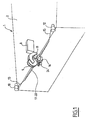
- a boat from surface referenced 1 as a whole and of which only the rear part is visible, is provided with a bridge 2 and a propulsion system comprising two propellers 3 and 4.
- the underwater object 6 can be, for example, a mine hunting submersible or exploration.
- the deflection pulley 9 is arranged cantilevered rearward.
- Three winches are also located at the back of Deck 2, a left side winch 10, a central winch 11 and a right lateral winch 12. On these winches are wound respectively support cables 13, 14 and 15. The free ends of the cables 13, 14 and 15 are attached to a dead body 16 which will be described in more detail with reference to FIG. 2.
- the central winch 11 is disposed in the immediate vicinity of the pulley 9, for example slightly below and in front of said idler pulley.
- plurality of rods 17 to 20 straight and arranged in a plane transverse to the boat, connect cables 13 to 15 together.
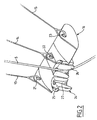
- the dead body 16 illustrated in greater detail in FIG. 2, is of a mass of the order of one or several hundred kilos and can be realized with a hydrodynamic shape to avoid energy loss important when moving the boat, the dead body 16 being immersed.
- the support cables 13 to 15 are connected and fixed respectively in anchoring holes 21 through 23 of the dead body 16.
- the fastening hole 21 is arranged on the left side of the dead body 16, the fastening hole 22 is arranged in the center and the attachment hole 23 is arranged on the right side, in the direction progress of the boat.
- a cable guide 24 is associated with the dead body 16 in position central to the back of the fastening hole 22.
- the cable guide 24 is shaped annular and comprises two elements 25 and 26 each forming half of the cable guide 24 according to a section plane passing through the axis of said cable guide.
- the element 26 is fixed to the dead body 16 and the element 25 is articulated on the dead body 16 or on the element 26 to allow the opening of the cable guide, which is illustrated in Figure 2 in the open position.
- Axial drilling 27 through the cable guide 24 and has a flared shape at its two ends.
- the connecting cable 5 is intended to be arranged in the passage 27 and be able to slide in without risk of deterioration its flared shape at its upper end and its lower end.
- the winch 7, the tensioner 8 and the winches 10, 11 and 12 are each connected to a control unit, not shown for the sake of simplicity drawing, by wired or wireless link.
- the control unit includes a processor, memory means and a control program stored in the memory means and able to be executed by the processor.
- the control unit can be provided with manual control means like buttons, joysticks, touch screen, etc.
- the control unit is able to control the different stages of implementation of the object submarine 6 and the cable protection device.
- the winches 7 and 10 to 12 can be electric, hydraulic or pneumatic type.
- the connecting cable 5 is almost completely wound on the drum of the winch 7.
- the underwater object 6 is disposed on the deck 2 and is attached thereto removable.
- the dead body 16 is raised in the upper position thanks to the winch 11, the lateral cables 13 and 15 being stretched between the winches respective 10 and 12 and the dead body 16, in almost horizontal position.
- the dead body 16 is below and near the idler pulley 9.
- the dead body 16 can be blocked by locking means integral with the boat 2 and more rigid than a cable connection.
- the winches 10 to 12 and the winch 7 are then ordered to deviate their respective cables, the load of the dead body 16 being supported by the central winch 11.
- the side cables 13 and 15 are kept at low voltage, just enough to avoid slack.
- the winches 10 and 12 are controlled to tension the lateral cables 13 and 15 and take back the weight of the dead body 16.
- the connecting cable 5 is maintained under low tension to avoid slackening. It will be noted that the cable unwinding speed must be adapted at each moment of the launching procedure due to the geometry of the set.
- the connecting cable 5 passing through the cable guide 24 is attached at its end to the underwater object 6 which remains on the bridge 2.
- the connecting cable 5 makes a go between the pulley of 9 and the cable guide 24 and a return between the cable guide 24 and the object submarine 6.
- the control unit allows, thanks to its control, to obtain desired unwinding speeds.
- the lengths of the lateral cables 13 and 15 are adjusted to remain equal in order to avoid unbalancing the dead body 16, especially with the speed of movement of the boat.
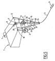
- the submarine object 6 is set to water using a crane not shown and can then move away from the boat, as shown in Figure 5.
- the deployed state (dead body 16 immersed) of the protective device is clearly visible in FIG. different cables 5, 10 and 12 are represented as being perfectly rights, which will not necessarily be the case in real situations.
- the cable of link 5 is arranged behind the support cable 14 that it hides. The cable of support 14 is therefore not visible in FIG.
- the rods 17 to 20 which are attached to heights staggered on the cables 10 and 12 are deployed parallel to one another substantially horizontally.
- the rods 17 to 20 can be formed by tubes whose ends are provided with rings so as to be able to slide along cables 13 to 15.
- a central ring is also provided to be able to slide along the central cable 14.
- the spacing between rods 17 to 20 is provided by spacing ropes 28, 29, 30 and 31. All there are two spacers, one on each side of the boat.
- the ropes 28 are fixed firstly to the rear of the boat, for example on the bridge 2 and on the other hand at one end of the rod 17.
- the ropes 29 are arranged at one end on the rod 17 and at the other end on the rod 18.
- the ropes 30 are attached at one end to the rod 18 and at the other end on the rod 19.
- the ropes 31 are attached to one end on the rod 19 and at the other end on the rod 20.
- the lines 28 to 31 can move to inside the respective rods or slide in rings for allow an adaptation of the geometry of the ropes and rods according the desired depth of the dead body 16.
- FIG. 7 illustrates a variant in which the protection device comprises a dead body 16 held by two carrying cables 32 and 33 spaced from each other by a distance for example of the order of one meter and arranged towards the middle of the ship 1.
- the cables 32 and 33 can be wound on a single double drum winch referenced 34 or, not shown, on two separate winches.
- the rods that maintain the spacing between cables 32 and 33 are here from annular shape and bear the reference 35.
- the annular rods 35 are connected to each other by means of strands 36. At least two strands 36 are provided between two stems annular 35 neighbors, but preferably three or more for a better holding in position.
- the annular rods 35 are able to slide, by example by means of rings, with respect to the carrying cables 32 and 33, and unfold during the immersion of the dead body 16. The annular rods 35 come to rest on the dead body 16 during its ascent.
- the cable of connection 5 is thus guided between the pulley 9 and the dead body 16 by the plurality of annular rods 35, the annular rods 35 having a spacing along the carrier cables 32 and 33, that is substantially along a vertical axis, determined by the spacing strings 36.
- the rod annular 35 upper will be connected to the boat 1, for example to the bridge 2, by a rope not shown.
- the invention makes it possible to guide the connecting cable below the propellers and interpose a curtain deployed between said connecting cable and the propellers or, more generally, the means of propulsion, to prevent a possible displacement of the connecting cable to these propulsion means.
- the heavy dead body equipped with a lockable cable guide is immersed by the rear of the boat below the level of the means of propulsion.
- At minus two auxiliary cables are attached on both sides of the dead body and on the sides of the back shelf with the function of preventing the body death to turn and maintain the protective rods that form a curtain between the connecting cable and the propulsion means. Winches of maneuvering support cables allow to lower or to go up the dead body and more generally the protection device between his storage position out of water and its operational position submerged.
- the protection device is easily deployable and foldable. It has a small footprint in the folded state in the measure where the protective rods, whether straight or annular, can stack on top of each other. The depth of immersion of the dead body can be adjusted precisely thanks to the winches.
- the time of implementation of the protective devices is very brief and the driving energy during the immersion is ensured by the force of gravity on the dead body and is therefore done without energy consumption from the boat.
- the geometry of the protective device is adaptable to a boat to another playing on the length of the protective rods when straight and relatively universal in the case of stems annular protection.
- provision can be made for the device in the folded state protection is a height requirement of the order of one meter.
- the deployment time may be of the order of 2 minutes.
Landscapes
- Chemical & Material Sciences (AREA)
- Engineering & Computer Science (AREA)
- Combustion & Propulsion (AREA)
- Mechanical Engineering (AREA)
- Ocean & Marine Engineering (AREA)
- Laying Of Electric Cables Or Lines Outside (AREA)
- Electric Cable Installation (AREA)
- Cable Accessories (AREA)
Claims (11)
- Schutzvorrichtung für ein Kabel, das ein Boot (1) an der Oberfläche mit einem Unterwassergegenstand (6) verbindet, dadurch gekennzeichnet, dass sie eine Ankerboje (16), eine der Ankerboje zugeordnete Kabelführung (24), mindestens zwei Stützkabel für die Ankerboje und mindestens ein Verbindungsorgan aufweist, das die Stützkabel verbindet und im Wesentlichen quer zu den Stützkabeln montiert ist.
- Vorrichtung nach Anspruch 1, dadurch gekennzeichnet, dass die Stützkabel der Ankerboje beiderseits des das Schiff mit dem Unterwassergegenstand verbindenden Kabels angeordnet sind.
- Vorrichtung nach Anspruch 1 oder 2, dadurch gekennzeichnet, dass die Stützkabel der Ankerboje im Wesentlichen quer zum Schiff angeordnet sind.
- Vorrichtung nach einem der vorhergehenden Ansprüche, dadurch gekennzeichnet, dass sie mindestens drei Stützkabel (13, 14, 15) der Ankerboje umfasst.
- Vorrichtung nach Anspruch 4, dadurch gekennzeichnet, dass ein Kabel in mittiger Position ist und die anderen Kabel in seitlicher Position sind, im Wesentlichen in einer Querebene zum Schiff.
- Vorrichtung nach einem der vorhergehenden Ansprüche, dadurch gekennzeichnet, dass sie ein Wickelmittel mittels Kabel umfasst.
- Vorrichtung nach einem der vorhergehenden Ansprüche, dadurch gekennzeichnet, dass das Verbindungsorgan mindestens eine mindestens zwei Stützkabel verbindende Stange umfasst.
- Vorrichtung nach Anspruch 7, dadurch gekennzeichnet, dass die Stange (17) eine allgemein gerade Form hat und im Wesentlichen in der Horizontalen angeordnet ist.
- Vorrichtung nach Anspruch 7, dadurch gekennzeichnet, dass die Stange (35) allgemein kreisförmig ist und im Wesentlichen in der Horizontalen angeordnet ist.
- Vorrichtung nach einem der vorhergehenden Ansprüche, dadurch gekennzeichnet, dass sie eine Steuereinheit zum Wickeln der Kabel umfasst.
- Vorrichtung nach Anspruch 10, dadurch gekennzeichnet, dass die Steuereinheit ein Rechner- oder Automatenprogramm mit Progammkodemitteln umfasst, um Ausbringungsschritte der Vorrichtung zu verwirklichen, wenn das Programm auf einem Rechner oder einem Automaten läuft.
Applications Claiming Priority (2)
| Application Number | Priority Date | Filing Date | Title |
|---|---|---|---|
| FR0007896 | 2000-06-21 | ||
| FR0007896A FR2810627B1 (fr) | 2000-06-21 | 2000-06-21 | Dispositif de protection d'un cable de liaison d'un objet sous-marin |
Publications (2)
| Publication Number | Publication Date |
|---|---|
| EP1167178A1 EP1167178A1 (de) | 2002-01-02 |
| EP1167178B1 true EP1167178B1 (de) | 2005-08-31 |
Family
ID=8851478
Family Applications (1)
| Application Number | Title | Priority Date | Filing Date |
|---|---|---|---|
| EP01401559A Expired - Lifetime EP1167178B1 (de) | 2000-06-21 | 2001-06-14 | Schutzvorrichtung für ein Versorgungskabel eines Unterwassergegenstandes |
Country Status (5)
| Country | Link |
|---|---|
| EP (1) | EP1167178B1 (de) |
| AT (1) | ATE303289T1 (de) |
| DE (1) | DE60113008T2 (de) |
| DK (1) | DK1167178T3 (de) |
| FR (1) | FR2810627B1 (de) |
Family Cites Families (5)
| Publication number | Priority date | Publication date | Assignee | Title |
|---|---|---|---|---|
| FR908304A (fr) * | 1944-12-19 | 1946-04-05 | Dragueurs de mines | |
| DE921781C (de) * | 1952-01-16 | 1954-12-30 | Hochseefischerei Nordstern A G | Hoehenspreizgeraet fuer Fischnetze |
| US4184209A (en) * | 1952-10-10 | 1980-01-15 | Crist Ralph P | Towed noisemaker |
| FR2296562A1 (fr) * | 1975-01-06 | 1976-07-30 | Inst Francais Du Petrole | Dispositif flottant relie a un navire pour remorquer un element immerge en le deportant par rapport a la route du navire |
| NO158359C (no) * | 1986-02-14 | 1988-08-24 | Geco As | Vinkelledd for seismiske kabler som slepes av et fartoey. |
-
2000
- 2000-06-21 FR FR0007896A patent/FR2810627B1/fr not_active Expired - Fee Related
-
2001
- 2001-06-14 DE DE60113008T patent/DE60113008T2/de not_active Expired - Fee Related
- 2001-06-14 EP EP01401559A patent/EP1167178B1/de not_active Expired - Lifetime
- 2001-06-14 DK DK01401559T patent/DK1167178T3/da active
- 2001-06-14 AT AT01401559T patent/ATE303289T1/de not_active IP Right Cessation
Also Published As
| Publication number | Publication date |
|---|---|
| ATE303289T1 (de) | 2005-09-15 |
| FR2810627B1 (fr) | 2002-08-30 |
| EP1167178A1 (de) | 2002-01-02 |
| FR2810627A1 (fr) | 2001-12-28 |
| DE60113008D1 (de) | 2005-10-06 |
| DE60113008T2 (de) | 2006-06-29 |
| DK1167178T3 (da) | 2006-01-09 |
Similar Documents
| Publication | Publication Date | Title |
|---|---|---|
| EP2809571B1 (de) | Aufnahmevorrichtung zur aufnahme eines seeschiffes und system zur rückholung und aussetzung solch eines schiffes im meer | |
| EP0478742B1 (de) | Verfahren und vorrichtung zur ungefähr vertikal ausgerichteten abwicklung von schläuchen | |
| EP0030909B1 (de) | Vorrichtungen und Verfahren zum Übersetzen zwischen einem Schiff und einer ortsfesten Konstruktion in offener See | |
| FR2823485A1 (fr) | Dispositif de mise a l'eau et de recuperation d'un vehicule sous-marin et procede de mise en oeuvre | |
| WO2000066922A1 (fr) | Navire de pose de conduites rigides a grandes profondeurs | |
| FR3091256A1 (fr) | Dispositif d’accueil pour un vehicule sous-marin | |
| FR2590539A1 (fr) | Systeme d'amarrage a cable unique, et procede de realisation d'un terminal de haute mer utilisant un tel systeme | |
| FR3091258A1 (fr) | Dispositif d’accueil pour un véhicule sous-marin | |
| EP2771235B1 (de) | Anlage zur verankerung einer schwimmenden plattform im boden | |
| FR2990770A1 (fr) | Procede et systeme de recuperation pour des flutes marines de capteur de recherche geophysique marine | |
| EP2468621B1 (de) | Vorrichtung zur Zuwasserlassung und Bergung eines Unterwasser- oder Oberflächengeräts | |
| FR3062844A1 (fr) | Systeme de mise a l'eau et de recuperation d'un engin propulse depuis le pont d'un navire porteur | |
| EP3209546B1 (de) | System zum aussetzen und bergen von see- und unterseevorrichtungen mit unterstützung durch kippbare schutzkomponenten | |
| EP1167178A1 (de) | Schutzvorrichtung für ein Versorgungskabel eines Unterwassergegenstandes | |
| EP3347668B1 (de) | Vorrichtung zum transportieren eines torpedos von einem transportwagen zu einem abschussrohr | |
| CA1067352A (fr) | Dispositif de mise en tension de lignes d'ancrage | |
| WO2015011291A1 (fr) | Pale d'eolienne segmentee munie d'un dispositif d'assemblage | |
| FR2636616A1 (fr) | Grue repliable a fleche en deux ou trois elements articules les uns aux autres | |
| FR2967749A1 (fr) | Dispositif de mise sous tension et de serrage d'un element allonge de forme tubulaire | |
| FR2544446A1 (fr) | Procede pour realiser les atterrissages d'arrivee de cables sous-marins | |
| CA3238311A1 (fr) | Systeme de traction a aile captive muni d'un socle a espace interne de stockage | |
| FR2549803A1 (fr) | Bossoir a longue portee pour embarcation de sauvetage | |
| EP0290510B1 (de) | Vorrichtung für handhabung, transport und lagerung von sportbooten | |
| FR3066485A1 (fr) | Systeme d'immersion d'un objet a partir d'une plateforme flottante ou non | |
| EP2685027A2 (de) | Plattenhubmaschine mit Sicherheitsvorrichtung zum Verlegen von Platten im Gebäudebereich |
Legal Events
| Date | Code | Title | Description |
|---|---|---|---|
| PUAI | Public reference made under article 153(3) epc to a published international application that has entered the european phase |
Free format text: ORIGINAL CODE: 0009012 |
|
| AK | Designated contracting states |
Kind code of ref document: A1 Designated state(s): AT BE CH CY DE DK ES FI FR GB GR IE IT LI LU MC NL PT SE TR |
|
| AX | Request for extension of the european patent |
Free format text: AL;LT;LV;MK;RO;SI |
|
| 17P | Request for examination filed |
Effective date: 20020628 |
|
| AKX | Designation fees paid |
Free format text: AT BE CH CY DE DK ES FI FR GB GR IE IT LI LU MC NL PT SE TR |
|
| 17Q | First examination report despatched |
Effective date: 20031219 |
|
| GRAP | Despatch of communication of intention to grant a patent |
Free format text: ORIGINAL CODE: EPIDOSNIGR1 |
|
| GRAS | Grant fee paid |
Free format text: ORIGINAL CODE: EPIDOSNIGR3 |
|
| GRAA | (expected) grant |
Free format text: ORIGINAL CODE: 0009210 |
|
| AK | Designated contracting states |
Kind code of ref document: B1 Designated state(s): AT BE CH CY DE DK ES FI FR GB GR IE IT LI LU MC NL PT SE TR |
|
| PG25 | Lapsed in a contracting state [announced via postgrant information from national office to epo] |
Ref country code: AT Free format text: LAPSE BECAUSE OF FAILURE TO SUBMIT A TRANSLATION OF THE DESCRIPTION OR TO PAY THE FEE WITHIN THE PRESCRIBED TIME-LIMIT Effective date: 20050831 Ref country code: IE Free format text: LAPSE BECAUSE OF FAILURE TO SUBMIT A TRANSLATION OF THE DESCRIPTION OR TO PAY THE FEE WITHIN THE PRESCRIBED TIME-LIMIT Effective date: 20050831 Ref country code: FI Free format text: LAPSE BECAUSE OF FAILURE TO SUBMIT A TRANSLATION OF THE DESCRIPTION OR TO PAY THE FEE WITHIN THE PRESCRIBED TIME-LIMIT Effective date: 20050831 |
|
| REG | Reference to a national code |
Ref country code: CH Ref legal event code: EP Ref country code: GB Ref legal event code: FG4D Free format text: NOT ENGLISH |
|
| REG | Reference to a national code |
Ref country code: IE Ref legal event code: FG4D Free format text: LANGUAGE OF EP DOCUMENT: FRENCH |
|
| REF | Corresponds to: |
Ref document number: 60113008 Country of ref document: DE Date of ref document: 20051006 Kind code of ref document: P |
|
| PG25 | Lapsed in a contracting state [announced via postgrant information from national office to epo] |
Ref country code: GR Free format text: LAPSE BECAUSE OF FAILURE TO SUBMIT A TRANSLATION OF THE DESCRIPTION OR TO PAY THE FEE WITHIN THE PRESCRIBED TIME-LIMIT Effective date: 20051130 |
|
| PG25 | Lapsed in a contracting state [announced via postgrant information from national office to epo] |
Ref country code: ES Free format text: LAPSE BECAUSE OF FAILURE TO SUBMIT A TRANSLATION OF THE DESCRIPTION OR TO PAY THE FEE WITHIN THE PRESCRIBED TIME-LIMIT Effective date: 20051212 |
|
| REG | Reference to a national code |
Ref country code: SE Ref legal event code: TRGR |
|
| GBT | Gb: translation of ep patent filed (gb section 77(6)(a)/1977) |
Effective date: 20051201 |
|
| REG | Reference to a national code |
Ref country code: DK Ref legal event code: T3 |
|
| PG25 | Lapsed in a contracting state [announced via postgrant information from national office to epo] |
Ref country code: PT Free format text: LAPSE BECAUSE OF FAILURE TO SUBMIT A TRANSLATION OF THE DESCRIPTION OR TO PAY THE FEE WITHIN THE PRESCRIBED TIME-LIMIT Effective date: 20060222 |
|
| REG | Reference to a national code |
Ref country code: IE Ref legal event code: FD4D |
|
| PG25 | Lapsed in a contracting state [announced via postgrant information from national office to epo] |
Ref country code: SE Free format text: LAPSE BECAUSE OF NON-PAYMENT OF DUE FEES Effective date: 20060615 |
|
| PG25 | Lapsed in a contracting state [announced via postgrant information from national office to epo] |
Ref country code: MC Free format text: LAPSE BECAUSE OF NON-PAYMENT OF DUE FEES Effective date: 20060630 Ref country code: LI Free format text: LAPSE BECAUSE OF NON-PAYMENT OF DUE FEES Effective date: 20060630 Ref country code: BE Free format text: LAPSE BECAUSE OF NON-PAYMENT OF DUE FEES Effective date: 20060630 Ref country code: CH Free format text: LAPSE BECAUSE OF NON-PAYMENT OF DUE FEES Effective date: 20060630 Ref country code: DK Free format text: LAPSE BECAUSE OF NON-PAYMENT OF DUE FEES Effective date: 20060630 |
|
| PLBE | No opposition filed within time limit |
Free format text: ORIGINAL CODE: 0009261 |
|
| STAA | Information on the status of an ep patent application or granted ep patent |
Free format text: STATUS: NO OPPOSITION FILED WITHIN TIME LIMIT |
|
| 26N | No opposition filed |
Effective date: 20060601 |
|
| PG25 | Lapsed in a contracting state [announced via postgrant information from national office to epo] |
Ref country code: NL Free format text: LAPSE BECAUSE OF NON-PAYMENT OF DUE FEES Effective date: 20070101 |
|
| REG | Reference to a national code |
Ref country code: DK Ref legal event code: EBP |
|
| REG | Reference to a national code |
Ref country code: CH Ref legal event code: PL |
|
| EUG | Se: european patent has lapsed | ||
| NLV4 | Nl: lapsed or anulled due to non-payment of the annual fee |
Effective date: 20070101 |
|
| PGFP | Annual fee paid to national office [announced via postgrant information from national office to epo] |
Ref country code: DE Payment date: 20070612 Year of fee payment: 7 |
|
| PGFP | Annual fee paid to national office [announced via postgrant information from national office to epo] |
Ref country code: GB Payment date: 20070619 Year of fee payment: 7 |
|
| BERE | Be: lapsed |
Owner name: SOC. ECA Effective date: 20060630 |
|
| PGFP | Annual fee paid to national office [announced via postgrant information from national office to epo] |
Ref country code: IT Payment date: 20070616 Year of fee payment: 7 |
|
| PGFP | Annual fee paid to national office [announced via postgrant information from national office to epo] |
Ref country code: FR Payment date: 20070516 Year of fee payment: 7 |
|
| PG25 | Lapsed in a contracting state [announced via postgrant information from national office to epo] |
Ref country code: TR Free format text: LAPSE BECAUSE OF FAILURE TO SUBMIT A TRANSLATION OF THE DESCRIPTION OR TO PAY THE FEE WITHIN THE PRESCRIBED TIME-LIMIT Effective date: 20050831 Ref country code: LU Free format text: LAPSE BECAUSE OF NON-PAYMENT OF DUE FEES Effective date: 20060614 |
|
| PG25 | Lapsed in a contracting state [announced via postgrant information from national office to epo] |
Ref country code: CY Free format text: LAPSE BECAUSE OF FAILURE TO SUBMIT A TRANSLATION OF THE DESCRIPTION OR TO PAY THE FEE WITHIN THE PRESCRIBED TIME-LIMIT Effective date: 20050831 |
|
| GBPC | Gb: european patent ceased through non-payment of renewal fee |
Effective date: 20080614 |
|
| REG | Reference to a national code |
Ref country code: FR Ref legal event code: ST Effective date: 20090228 |
|
| PG25 | Lapsed in a contracting state [announced via postgrant information from national office to epo] |
Ref country code: DE Free format text: LAPSE BECAUSE OF NON-PAYMENT OF DUE FEES Effective date: 20090101 |
|
| PG25 | Lapsed in a contracting state [announced via postgrant information from national office to epo] |
Ref country code: GB Free format text: LAPSE BECAUSE OF NON-PAYMENT OF DUE FEES Effective date: 20080614 |
|
| PG25 | Lapsed in a contracting state [announced via postgrant information from national office to epo] |
Ref country code: FR Free format text: LAPSE BECAUSE OF NON-PAYMENT OF DUE FEES Effective date: 20080630 Ref country code: IT Free format text: LAPSE BECAUSE OF NON-PAYMENT OF DUE FEES Effective date: 20080614 |