EP1167700A2 - Agencement de soupape pour moteur à combustion interne - Google Patents
Agencement de soupape pour moteur à combustion interne Download PDFInfo
- Publication number
- EP1167700A2 EP1167700A2 EP01103822A EP01103822A EP1167700A2 EP 1167700 A2 EP1167700 A2 EP 1167700A2 EP 01103822 A EP01103822 A EP 01103822A EP 01103822 A EP01103822 A EP 01103822A EP 1167700 A2 EP1167700 A2 EP 1167700A2
- Authority
- EP
- European Patent Office
- Prior art keywords
- valve
- suction
- exhaust
- valve seat
- axis
- Prior art date
- Legal status (The legal status is an assumption and is not a legal conclusion. Google has not performed a legal analysis and makes no representation as to the accuracy of the status listed.)
- Granted
Links
- 238000002485 combustion reaction Methods 0.000 title claims abstract description 22
- 230000000694 effects Effects 0.000 description 4
- 239000000446 fuel Substances 0.000 description 4
- 230000002079 cooperative effect Effects 0.000 description 2
- 239000012530 fluid Substances 0.000 description 2
- 239000000126 substance Substances 0.000 description 2
- 239000000203 mixture Substances 0.000 description 1
Images


Classifications
-
- F—MECHANICAL ENGINEERING; LIGHTING; HEATING; WEAPONS; BLASTING
- F02—COMBUSTION ENGINES; HOT-GAS OR COMBUSTION-PRODUCT ENGINE PLANTS
- F02B—INTERNAL-COMBUSTION PISTON ENGINES; COMBUSTION ENGINES IN GENERAL
- F02B31/00—Modifying induction systems for imparting a rotation to the charge in the cylinder
-
- F—MECHANICAL ENGINEERING; LIGHTING; HEATING; WEAPONS; BLASTING
- F01—MACHINES OR ENGINES IN GENERAL; ENGINE PLANTS IN GENERAL; STEAM ENGINES
- F01L—CYCLICALLY OPERATING VALVES FOR MACHINES OR ENGINES
- F01L3/00—Lift-valve, i.e. cut-off apparatus with closure members having at least a component of their opening and closing motion perpendicular to the closing faces; Parts or accessories thereof
- F01L3/06—Valve members or valve-seats with means for guiding or deflecting the medium controlled thereby, e.g. producing a rotary motion of the drawn-in cylinder charge
-
- F—MECHANICAL ENGINEERING; LIGHTING; HEATING; WEAPONS; BLASTING
- F02—COMBUSTION ENGINES; HOT-GAS OR COMBUSTION-PRODUCT ENGINE PLANTS
- F02B—INTERNAL-COMBUSTION PISTON ENGINES; COMBUSTION ENGINES IN GENERAL
- F02B31/00—Modifying induction systems for imparting a rotation to the charge in the cylinder
- F02B31/08—Modifying induction systems for imparting a rotation to the charge in the cylinder having multiple air inlets
- F02B31/085—Modifying induction systems for imparting a rotation to the charge in the cylinder having multiple air inlets having two inlet valves
-
- Y—GENERAL TAGGING OF NEW TECHNOLOGICAL DEVELOPMENTS; GENERAL TAGGING OF CROSS-SECTIONAL TECHNOLOGIES SPANNING OVER SEVERAL SECTIONS OF THE IPC; TECHNICAL SUBJECTS COVERED BY FORMER USPC CROSS-REFERENCE ART COLLECTIONS [XRACs] AND DIGESTS
- Y02—TECHNOLOGIES OR APPLICATIONS FOR MITIGATION OR ADAPTATION AGAINST CLIMATE CHANGE
- Y02T—CLIMATE CHANGE MITIGATION TECHNOLOGIES RELATED TO TRANSPORTATION
- Y02T10/00—Road transport of goods or passengers
- Y02T10/10—Internal combustion engine [ICE] based vehicles
- Y02T10/12—Improving ICE efficiencies
Definitions
- the present invention relates to a valve seat of a suction or exhaust valve of an internal combustion engine capable of achieving high suction or exhaust performance.
- Fig. 6 is a longitudinal sectional view showing an example of a suction (exhaust) valve and a valve seat of a customary internal combustion engine.
- 01, 02 and 03 denote a cylinder head, a suction or exhaust valve and a valve seat, respectively.
- an axis 02a of the suction (exhaust) valve 02 is directed parallel with a cylinder axis (not shown), that is, the valve is an upright type valve.
- an opening end of the valve seat is formed in a rounded shape 03a.
- Fig. 7 is a longitudinal sectional view showing another example of a suction (exhaust) valve and a valve seat of a customary internal combustion engine.
- the axis 02a of the suction (exhaust) valve 02 is not parallel with the cylinder axis, but the valve axis 02a is inclined relatively to the cylinder axis with an included angle to accept the valve within the bore.
- the customary valve seat shape as shown in Fig. 6 it is difficult to make a high coefficient of discharge and a high swirl compatible with each other.
- the valve seat shape as shown in Fig. 7 the coefficient of discharge can be made high, but squish stream disappears or weakens to deteriorate combustion.
- the present invention aims to make a high coefficient of discharge and a high swirl ratio compatible with each other without exerting a bad influence on combustion.
- the present invention provides a valve device of an internal combustion engine including a suction valve arranged in a cylinder head having an axis directed parallel with a cylinder axis, wherein an edge part at a suction air outlet end of a valve seat of the suction valve is expanded in a direction along swirl stream.
- an edge part at a suction air outlet end of a valve seat of the suction valve is expanded in a direction along swirl stream, fluid resistance is reduced and directivity of suction air is increased, so that a high coefficient of discharge and a high swirl ratio can be made compatible without setting the valve with an included angle. If the direction of expanding of the edge part is changed suitably, it is possible to change only swirl as occasion demands while maintaining coefficient of discharge high.
- valve device is an upright type one in which a suction valve has an axis parallel with a cylinder axis to form a flat combustion chamber, squish stream can be utilized for improving combustion by cooperative effect with the swirl so that fuel consumption is improved and harmful substance in exhaust gas is reduced.
- swirl ratio can be improved at will merely by applying an additional working to an already worked valve seat and also the above-mentioned direction of expanding can be set freely. Therefore, improvement of a present valve seat is also easy.
- a valve device of an internal combustion engine including an exhaust valve arranged in a cylinder head having an axis directed parallel with a cylinder axis, wherein an edge part at an exhaust gas inlet end of a valve seat of the exhaust valve is expanded toward the cylinder axis is provided.
- coefficient of discharge can be raised by expanding an edge part at an exhaust gas inlet end of a valve seat of the exhaust valve in a direction.
- advantage of the upright type valve can be utilized and additional working of an already worked valve seat or improvement of a present valve seat is easy.
- Fig. 1a is a longitudinal sectional side view of a valve seat of a suction (exhaust) valve according to an embodiment of the present invention
- Fig. 1b is a plan view of an opening end of the valve seat
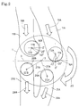
- Fig. 2 is a view showing arrangement of suction valves and exhaust valves in a cylinder head and direction of expanding of opening end edge parts of the valve seats.
- 1, 11, 12 and 13 denote a cylinder head, a suction port, an axis of a suction valve (not shown) and a valve seat, respectively.
- the present embodiment is what is called an upright type valve and the axis 12 of the suction valve is parallel with an axis of a cylinder.
- the rotary surface 15 is additionally shaved extending over a half circumference about an offset axis 18 shifted from the axis 15 in one direction (right direction in the figure), so that an edge part 16 of a suction air outlet end 14 of the valve seat is expanded in one direction (right direction in the figure) from the rotary surface 15.
- a valve seat of an exhaust valve This is the same regarding a valve seat of an exhaust valve.
- Fig. 2 1 denotes the cylinder head
- 11A and 11B denote suction ports
- 12A and 12B denote axes of suction valves (not shown)
- 16A and 16B denote suction air outlet end edges of valve seats of the suction valves
- 21A and 21B denote exhaust ports
- 22A and 22B denote axes of exhaust valves (not shown)
- 26A and 26B denote exhaust gas inlet end edges of valve seats of the exhaust valves.
- Air and fuel in suction air (air-fuel mixture to be exact) 19A, 19B inhaled into a combustion chamber from the suction port 11A, 11B through the suction valve are mixed with each other well by swirl stream 20 generated within the combustion chamber and burned.
- Resulted exhaust gas 29A, 29B is discharged to the exhaust port 21A, 21B through the exhaust valve.
- the direction of expanding 17A of the suction air outlet edge part 16A of a suction valve seat is perpendicular to a plane including a cylinder axis 2 and a crankshaft axis 3, and the direction of expanding 17B of the suction air outlet edge part 16B of another suction valve seat is parallel with the above-mentioned plane. Both of these directions 17A and 17B correspond to direction of the swirl stream 20.
- the directions of expanding 27A and 27B of exhaust gas inlet end edge parts 26A and 26B of the exhaust valve seats are both directed toward the cylinder axis 2.
- an edge part 16A, 16B at a suction air outlet end of a valve seat of the suction valve is expanded in a direction along swirl stream 20, fluid resistance is reduced and directivity of suction air is increased, so that both a high coefficient of discharge and a high swirl ratio can be realized without setting the valve with an included angle. If the direction of expanding 17A, 17B of the edge part is changed suitably, it is possible to change only swirl as occasion demands while maintaining coefficient of discharge high. Regarding the exhaust valve too, coefficient of discharge can be raised by expanding the edge part 20A, 20B at the exhaust gas outlet end of the valve seat in a direction.
- valve Since the valve is an upright type one and therefore the combustion chamber is flat, squish stream can be utilized for improving combustion by cooperative effect with the swirl, so that fuel consumption is improved and harmful substance in exhaust gas is reduced.
- swirl ratio can be improved at will merely by applying an additional working to an already worked valve seat and also the above-mentioned direction of expanding can be set freely. Therefore, improvement of a present valve seat is also easy.
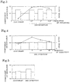
- the direction of expanding 17A of the edge part of the first suction valve 12A was changed in three ways as shown in Fig. 2 while keeping the second suction valve 12B closed and coefficient of discharge and swirl ratio were measured for each case to be compared with those of the customary valve shown in Fig. 6.
- the result is shown in Fig. 3, in which the bar graph shows coefficients of discharge and the bent line shows swirl ratios.
- the direction of expanding 17B of the edge part of the second suction valve 12B was changed in three ways as shown in Fig. 2 while keeping the direction of expanding 17A of the edge part of the first suction valve 12A at 0° in the state that both suction valves are open, and coefficient of discharge and swirl ratio were measured for each case to be compared with those of the customary valve.
- Fig. 4 the direction of expanding 17A of the edge part of the first suction valve 12A was changed in three ways as shown in Fig. 2 while keeping the second suction valve 12B closed and coefficient of discharge and swirl ratio were measured for each case to be compared with
- swirl ratio can be markedly improved compared with the customary one without lowering coefficient of discharge. Further, it can be also known that by changing the direction of expanding of the edge part of the valve seat, swirl ratio can be changed largely while maintaining coefficient of discharge constant.
- Fig. 5 shows coefficient of discharge of the exhaust valve of the present invention in comparison with that of the customary valve shown in Fig. 6. It is known that regarding the exhaust valve too, coefficient of discharge is improved according to the present invention.
- a valve seat of a suction or exhaust valve of an internal combustion engine capable of making a high coefficient of discharge and a high swirl ratio compatible with each other without exerting a bad influence on combustion is provided.
- a valve device includes a suction valve arranged in a cylinder head having an axis directed parallel with a cylinder axis. An edge part at a suction air outlet end of a valve seat of the suction valve is expanded in a direction along swirl stream.
- the valve device includes an exhaust valve arranged in a cylinder head having an axis directed parallel with a cylinder axis, and an edge part at an exhaust gas inlet end of a valve seat of the exhaust valve is expanded toward the cylinder axis.
Landscapes
- Engineering & Computer Science (AREA)
- Mechanical Engineering (AREA)
- General Engineering & Computer Science (AREA)
- Chemical & Material Sciences (AREA)
- Combustion & Propulsion (AREA)
- Cylinder Crankcases Of Internal Combustion Engines (AREA)
- Combustion Methods Of Internal-Combustion Engines (AREA)
Applications Claiming Priority (2)
| Application Number | Priority Date | Filing Date | Title |
|---|---|---|---|
| JP2000183989A JP2002004821A (ja) | 2000-06-20 | 2000-06-20 | 内燃機関の弁座 |
| JP2000183989 | 2000-06-20 |
Publications (3)
| Publication Number | Publication Date |
|---|---|
| EP1167700A2 true EP1167700A2 (fr) | 2002-01-02 |
| EP1167700A3 EP1167700A3 (fr) | 2003-02-05 |
| EP1167700B1 EP1167700B1 (fr) | 2005-01-19 |
Family
ID=18684483
Family Applications (1)
| Application Number | Title | Priority Date | Filing Date |
|---|---|---|---|
| EP01103822A Expired - Lifetime EP1167700B1 (fr) | 2000-06-20 | 2001-02-15 | Agencement de soupape pour moteur à combustion interne |
Country Status (3)
| Country | Link |
|---|---|
| EP (1) | EP1167700B1 (fr) |
| JP (1) | JP2002004821A (fr) |
| DE (1) | DE60108449T2 (fr) |
Cited By (9)
| Publication number | Priority date | Publication date | Assignee | Title |
|---|---|---|---|---|
| DE102004029386A1 (de) * | 2004-06-17 | 2006-01-05 | Deutz Ag | Bei interner Abgasrückführung wirksame Fase im Auslassventilsitzbereich |
| FR2887585A1 (fr) * | 2005-06-22 | 2006-12-29 | Renault Sas | Dispositif, pour moteur a combustion interne, de generation d'aerodynamique variable dans les conduits d'admission de la culasse |
| EP1944476A1 (fr) * | 2007-01-11 | 2008-07-16 | Peugeot Citroën Automobiles Sa | Siège de soupape usiné en deux chanfreins désaxés |
| EP1944477A1 (fr) * | 2007-01-11 | 2008-07-16 | Peugeot Citroën Automobiles Sa | Siège de soupape usiné en plusieurs chanfreins |
| WO2009062978A1 (fr) * | 2007-11-15 | 2009-05-22 | Renault S.A.S. | Culasse d'un moteur a combustion interne |
| EP1475529A4 (fr) * | 2000-08-14 | 2011-06-22 | Niigata Power Systems Co Ltd | Culasse de cylindre |
| EP2698508A1 (fr) * | 2012-08-17 | 2014-02-19 | MWM GmbH | Tête de vérin avec fraisure |
| CN104863743A (zh) * | 2015-04-01 | 2015-08-26 | 上海交通大学 | 内燃机缸盖、内燃机及装有这种内燃机的机械装置 |
| WO2017114137A1 (fr) * | 2015-12-29 | 2017-07-06 | 重庆志成机械有限公司 | Structure de siège de soupape pour culasse de moteur de motocyclette |
Families Citing this family (5)
| Publication number | Priority date | Publication date | Assignee | Title |
|---|---|---|---|---|
| US6983117B2 (en) * | 2002-08-23 | 2006-01-03 | Ricoh Company, Ltd. | Image forming apparatus configured for double sided printing |
| KR20040041364A (ko) * | 2002-11-11 | 2004-05-17 | 현대자동차주식회사 | 엔진의 흡기 밸브 시트 |
| JP4730355B2 (ja) * | 2007-08-29 | 2011-07-20 | トヨタ自動車株式会社 | 内燃機関のポート及びポート製造方法 |
| JP5381913B2 (ja) * | 2010-06-29 | 2014-01-08 | マツダ株式会社 | エンジンのシリンダヘッド構造 |
| CN103696868B (zh) * | 2013-12-10 | 2016-05-25 | 天津大学 | 具有高涡流与滚流比的内燃机缸盖 |
Family Cites Families (5)
| Publication number | Priority date | Publication date | Assignee | Title |
|---|---|---|---|---|
| GB277875A (en) * | 1927-03-28 | 1927-09-29 | Harry Ralph Ricardo | Improvements in and relating to valves for internal combustion engines |
| DE587675C (de) * | 1932-05-27 | 1933-11-07 | Pentaverken Ab | Brennkraftmaschine mit abgeschirmtem Einlassventil |
| GB1604623A (en) * | 1978-05-31 | 1981-12-09 | Balston A F | Diesel internal combustion engines |
| JPH0663452B2 (ja) * | 1986-07-04 | 1994-08-22 | トヨタ自動車株式会社 | 2サイクル内燃機関 |
| DE59705848D1 (de) * | 1996-06-20 | 2002-01-31 | Volkswagen Ag | Verfahren und Vorrichtung zum Betreiben einer fremdgezündeten Hubkolben-Brennkraftmaschine |
-
2000
- 2000-06-20 JP JP2000183989A patent/JP2002004821A/ja active Pending
-
2001
- 2001-02-15 EP EP01103822A patent/EP1167700B1/fr not_active Expired - Lifetime
- 2001-02-15 DE DE60108449T patent/DE60108449T2/de not_active Expired - Lifetime
Cited By (14)
| Publication number | Priority date | Publication date | Assignee | Title |
|---|---|---|---|---|
| EP1475529A4 (fr) * | 2000-08-14 | 2011-06-22 | Niigata Power Systems Co Ltd | Culasse de cylindre |
| DE102004029386A1 (de) * | 2004-06-17 | 2006-01-05 | Deutz Ag | Bei interner Abgasrückführung wirksame Fase im Auslassventilsitzbereich |
| DE102004029386B4 (de) * | 2004-06-17 | 2015-11-12 | Deutz Ag | Bei interner Abgasrückführung wirksame Fase im Auslassventilsitzbereich |
| FR2887585A1 (fr) * | 2005-06-22 | 2006-12-29 | Renault Sas | Dispositif, pour moteur a combustion interne, de generation d'aerodynamique variable dans les conduits d'admission de la culasse |
| EP1944476A1 (fr) * | 2007-01-11 | 2008-07-16 | Peugeot Citroën Automobiles Sa | Siège de soupape usiné en deux chanfreins désaxés |
| EP1944477A1 (fr) * | 2007-01-11 | 2008-07-16 | Peugeot Citroën Automobiles Sa | Siège de soupape usiné en plusieurs chanfreins |
| FR2911367A1 (fr) * | 2007-01-11 | 2008-07-18 | Peugeot Citroen Automobiles Sa | Siege de soupape usine en plusieurs chanfreins |
| FR2911366A1 (fr) * | 2007-01-11 | 2008-07-18 | Peugeot Citroen Automobiles Sa | Siege de soupape usine en deux chanfreins desaxes |
| WO2009062978A1 (fr) * | 2007-11-15 | 2009-05-22 | Renault S.A.S. | Culasse d'un moteur a combustion interne |
| FR2923857A1 (fr) * | 2007-11-15 | 2009-05-22 | Renault Sas | Culasse d'un moteur a combustion interne |
| EP2698508A1 (fr) * | 2012-08-17 | 2014-02-19 | MWM GmbH | Tête de vérin avec fraisure |
| US20150219006A1 (en) * | 2012-08-17 | 2015-08-06 | Caterpillar Energy Solutions Gmbh | Cylinder head with countersink |
| CN104863743A (zh) * | 2015-04-01 | 2015-08-26 | 上海交通大学 | 内燃机缸盖、内燃机及装有这种内燃机的机械装置 |
| WO2017114137A1 (fr) * | 2015-12-29 | 2017-07-06 | 重庆志成机械有限公司 | Structure de siège de soupape pour culasse de moteur de motocyclette |
Also Published As
| Publication number | Publication date |
|---|---|
| DE60108449T2 (de) | 2005-06-23 |
| EP1167700A3 (fr) | 2003-02-05 |
| JP2002004821A (ja) | 2002-01-09 |
| DE60108449D1 (de) | 2005-02-24 |
| EP1167700B1 (fr) | 2005-01-19 |
Similar Documents
| Publication | Publication Date | Title |
|---|---|---|
| EP1167700A2 (fr) | Agencement de soupape pour moteur à combustion interne | |
| JP5024230B2 (ja) | 層状掃気2サイクルエンジン及び2サイクルエンジン工具 | |
| EP2018471B1 (fr) | Dispositif de commande d'admission pour moteur à combustion interne | |
| CN100458132C (zh) | 气缸头 | |
| CN101649770A (zh) | 2循环发动机及工具 | |
| GB1567812A (en) | Intake system for internal combustion engines | |
| CN1082618C (zh) | 内燃机活塞 | |
| JP3333298B2 (ja) | 筒内燃料噴射式の多気筒エンジン | |
| JP2628138B2 (ja) | 内燃機関における吸気ポート構造 | |
| EP3032065B1 (fr) | Moteur à deux temps avec balayage stratifié et carburateur pour celui-ci | |
| US5042440A (en) | Cylinder head for internal combustion engine | |
| JP4147981B2 (ja) | 直接筒内噴射式エンジンのインジェクタ配置構造 | |
| JPS632578Y2 (fr) | ||
| KR20010041124A (ko) | 내연기관 | |
| JP6750724B2 (ja) | 内燃機関の吸気ポート構造 | |
| US4467760A (en) | Internal combustion engine | |
| JPH08135514A (ja) | ガス燃料エンジンの燃料供給装置 | |
| US6722337B2 (en) | Spark ignition internal combustion engine | |
| JPH077544Y2 (ja) | エンジンの燃焼室構造 | |
| JP2566257B2 (ja) | エンジンの燃焼室構造 | |
| JPH0578953U (ja) | 内燃機関の燃焼室構造 | |
| JP2016188624A (ja) | 内燃機関 | |
| JPH0712672Y2 (ja) | 吸気構造 | |
| JP4074926B2 (ja) | プライマリー型摺動絞り弁型気化器 | |
| KR100827831B1 (ko) | 실린더 헤드 |
Legal Events
| Date | Code | Title | Description |
|---|---|---|---|
| PUAI | Public reference made under article 153(3) epc to a published international application that has entered the european phase |
Free format text: ORIGINAL CODE: 0009012 |
|
| AK | Designated contracting states |
Kind code of ref document: A2 Designated state(s): AT BE CH CY DE DK ES FI FR GB GR IE IT LI LU MC NL PT SE TR |
|
| AX | Request for extension of the european patent |
Free format text: AL;LT;LV;MK;RO;SI |
|
| PUAL | Search report despatched |
Free format text: ORIGINAL CODE: 0009013 |
|
| AK | Designated contracting states |
Designated state(s): AT BE CH CY DE DK ES FI FR GB GR IE IT LI LU MC NL PT SE TR |
|
| AX | Request for extension of the european patent |
Extension state: AL LT LV MK RO SI |
|
| 17P | Request for examination filed |
Effective date: 20030205 |
|
| 17Q | First examination report despatched |
Effective date: 20030407 |
|
| AKX | Designation fees paid |
Designated state(s): DE GB |
|
| GRAP | Despatch of communication of intention to grant a patent |
Free format text: ORIGINAL CODE: EPIDOSNIGR1 |
|
| GRAS | Grant fee paid |
Free format text: ORIGINAL CODE: EPIDOSNIGR3 |
|
| GRAA | (expected) grant |
Free format text: ORIGINAL CODE: 0009210 |
|
| AK | Designated contracting states |
Kind code of ref document: B1 Designated state(s): DE GB |
|
| REG | Reference to a national code |
Ref country code: GB Ref legal event code: FG4D |
|
| REG | Reference to a national code |
Ref country code: IE Ref legal event code: FG4D |
|
| REF | Corresponds to: |
Ref document number: 60108449 Country of ref document: DE Date of ref document: 20050224 Kind code of ref document: P |
|
| PLBE | No opposition filed within time limit |
Free format text: ORIGINAL CODE: 0009261 |
|
| STAA | Information on the status of an ep patent application or granted ep patent |
Free format text: STATUS: NO OPPOSITION FILED WITHIN TIME LIMIT |
|
| 26N | No opposition filed |
Effective date: 20051020 |
|
| PGFP | Annual fee paid to national office [announced via postgrant information from national office to epo] |
Ref country code: GB Payment date: 20100202 Year of fee payment: 10 Ref country code: DE Payment date: 20100226 Year of fee payment: 10 |
|
| GBPC | Gb: european patent ceased through non-payment of renewal fee |
Effective date: 20110215 |
|
| REG | Reference to a national code |
Ref country code: DE Ref legal event code: R119 Ref document number: 60108449 Country of ref document: DE Effective date: 20110901 |
|
| PG25 | Lapsed in a contracting state [announced via postgrant information from national office to epo] |
Ref country code: GB Free format text: LAPSE BECAUSE OF NON-PAYMENT OF DUE FEES Effective date: 20110215 |
|
| PG25 | Lapsed in a contracting state [announced via postgrant information from national office to epo] |
Ref country code: DE Free format text: LAPSE BECAUSE OF NON-PAYMENT OF DUE FEES Effective date: 20110901 |