EP2018471B1 - Dispositif de commande d'admission pour moteur à combustion interne - Google Patents
Dispositif de commande d'admission pour moteur à combustion interne Download PDFInfo
- Publication number
- EP2018471B1 EP2018471B1 EP07734473A EP07734473A EP2018471B1 EP 2018471 B1 EP2018471 B1 EP 2018471B1 EP 07734473 A EP07734473 A EP 07734473A EP 07734473 A EP07734473 A EP 07734473A EP 2018471 B1 EP2018471 B1 EP 2018471B1
- Authority
- EP
- European Patent Office
- Prior art keywords
- intake passage
- intake
- valve
- control valve
- internal combustion
- Prior art date
- Legal status (The legal status is an assumption and is not a legal conclusion. Google has not performed a legal analysis and makes no representation as to the accuracy of the status listed.)
- Ceased
Links
- 238000002485 combustion reaction Methods 0.000 title claims abstract description 257
- 238000005192 partition Methods 0.000 claims abstract description 61
- 230000000694 effects Effects 0.000 claims description 45
- 239000000446 fuel Substances 0.000 claims description 45
- 239000000203 mixture Substances 0.000 claims description 17
- 238000011144 upstream manufacturing Methods 0.000 claims description 8
- 238000005086 pumping Methods 0.000 description 3
- 230000001174 ascending effect Effects 0.000 description 1
- 238000002347 injection Methods 0.000 description 1
- 239000007924 injection Substances 0.000 description 1
- 230000010349 pulsation Effects 0.000 description 1
- 238000000638 solvent extraction Methods 0.000 description 1
- 230000001360 synchronised effect Effects 0.000 description 1
Images







Classifications
-
- F—MECHANICAL ENGINEERING; LIGHTING; HEATING; WEAPONS; BLASTING
- F02—COMBUSTION ENGINES; HOT-GAS OR COMBUSTION-PRODUCT ENGINE PLANTS
- F02B—INTERNAL-COMBUSTION PISTON ENGINES; COMBUSTION ENGINES IN GENERAL
- F02B27/00—Use of kinetic or wave energy of charge in induction systems, or of combustion residues in exhaust systems, for improving quantity of charge or for increasing removal of combustion residues
- F02B27/02—Use of kinetic or wave energy of charge in induction systems, or of combustion residues in exhaust systems, for improving quantity of charge or for increasing removal of combustion residues the systems having variable, i.e. adjustable, cross-sectional areas, chambers of variable volume, or like variable means
- F02B27/0205—Use of kinetic or wave energy of charge in induction systems, or of combustion residues in exhaust systems, for improving quantity of charge or for increasing removal of combustion residues the systems having variable, i.e. adjustable, cross-sectional areas, chambers of variable volume, or like variable means characterised by the charging effect
- F02B27/0215—Oscillating pipe charging, i.e. variable intake pipe length charging
-
- F—MECHANICAL ENGINEERING; LIGHTING; HEATING; WEAPONS; BLASTING
- F02—COMBUSTION ENGINES; HOT-GAS OR COMBUSTION-PRODUCT ENGINE PLANTS
- F02B—INTERNAL-COMBUSTION PISTON ENGINES; COMBUSTION ENGINES IN GENERAL
- F02B27/00—Use of kinetic or wave energy of charge in induction systems, or of combustion residues in exhaust systems, for improving quantity of charge or for increasing removal of combustion residues
- F02B27/02—Use of kinetic or wave energy of charge in induction systems, or of combustion residues in exhaust systems, for improving quantity of charge or for increasing removal of combustion residues the systems having variable, i.e. adjustable, cross-sectional areas, chambers of variable volume, or like variable means
-
- F—MECHANICAL ENGINEERING; LIGHTING; HEATING; WEAPONS; BLASTING
- F02—COMBUSTION ENGINES; HOT-GAS OR COMBUSTION-PRODUCT ENGINE PLANTS
- F02B—INTERNAL-COMBUSTION PISTON ENGINES; COMBUSTION ENGINES IN GENERAL
- F02B27/00—Use of kinetic or wave energy of charge in induction systems, or of combustion residues in exhaust systems, for improving quantity of charge or for increasing removal of combustion residues
- F02B27/02—Use of kinetic or wave energy of charge in induction systems, or of combustion residues in exhaust systems, for improving quantity of charge or for increasing removal of combustion residues the systems having variable, i.e. adjustable, cross-sectional areas, chambers of variable volume, or like variable means
- F02B27/0226—Use of kinetic or wave energy of charge in induction systems, or of combustion residues in exhaust systems, for improving quantity of charge or for increasing removal of combustion residues the systems having variable, i.e. adjustable, cross-sectional areas, chambers of variable volume, or like variable means characterised by the means generating the charging effect
- F02B27/0268—Valves
- F02B27/0273—Flap valves
-
- F—MECHANICAL ENGINEERING; LIGHTING; HEATING; WEAPONS; BLASTING
- F02—COMBUSTION ENGINES; HOT-GAS OR COMBUSTION-PRODUCT ENGINE PLANTS
- F02B—INTERNAL-COMBUSTION PISTON ENGINES; COMBUSTION ENGINES IN GENERAL
- F02B31/00—Modifying induction systems for imparting a rotation to the charge in the cylinder
- F02B31/04—Modifying induction systems for imparting a rotation to the charge in the cylinder by means within the induction channel, e.g. deflectors
- F02B31/06—Movable means, e.g. butterfly valves
-
- F—MECHANICAL ENGINEERING; LIGHTING; HEATING; WEAPONS; BLASTING
- F02—COMBUSTION ENGINES; HOT-GAS OR COMBUSTION-PRODUCT ENGINE PLANTS
- F02F—CYLINDERS, PISTONS OR CASINGS, FOR COMBUSTION ENGINES; ARRANGEMENTS OF SEALINGS IN COMBUSTION ENGINES
- F02F1/00—Cylinders; Cylinder heads
- F02F1/24—Cylinder heads
- F02F1/42—Shape or arrangement of intake or exhaust channels in cylinder heads
- F02F1/4235—Shape or arrangement of intake or exhaust channels in cylinder heads of intake channels
- F02F1/4242—Shape or arrangement of intake or exhaust channels in cylinder heads of intake channels with a partition wall inside the channel
-
- Y—GENERAL TAGGING OF NEW TECHNOLOGICAL DEVELOPMENTS; GENERAL TAGGING OF CROSS-SECTIONAL TECHNOLOGIES SPANNING OVER SEVERAL SECTIONS OF THE IPC; TECHNICAL SUBJECTS COVERED BY FORMER USPC CROSS-REFERENCE ART COLLECTIONS [XRACs] AND DIGESTS
- Y02—TECHNOLOGIES OR APPLICATIONS FOR MITIGATION OR ADAPTATION AGAINST CLIMATE CHANGE
- Y02T—CLIMATE CHANGE MITIGATION TECHNOLOGIES RELATED TO TRANSPORTATION
- Y02T10/00—Road transport of goods or passengers
- Y02T10/10—Internal combustion engine [ICE] based vehicles
- Y02T10/12—Improving ICE efficiencies
Definitions
- the present invention relates to an intake control device for an internal combustion engine.
- JP-A-7-197823 describes an intake control device for an internal combustion engine having two intake passages with different lengths from a surge tank to a combustion chamber and a passage length switching valve for switching the length of the intake passage from the surge tank to the combustion chamber depending on the operating condition of the internal combustion engine so that an inertia charging effect may be used to increase the amount of air to be drawn into the combustion chamber.
- the intake control device for an internal combustion engine described in JP-A-7-197823 has a tumble switching valve for forming a tumble flow of air in the combustion chamber in the intake passage upstream of the combustion chamber. When closed, the tumble switching valve partially closes the intake passage so that air can flow downstream along only one side of the tumble switching valve, that is, air flows downstream through only a portion of the intake passage to form a tumble flow of air into the combustion chamber.
- the intake passage is partially closed by the tumble switching valve to form a tumble flow of air in the combustion chamber in the intake control device for an internal combustion engine described in JP-A- 7-197823 , whereas there is also an intake device, as described in, for example, Japanese Patent Application Publication No. 2002-70566 ( JP-A-2002-70566 ), in which an intake passage is partitioned into two passages and one of the passages may be closed by a tumble control valve at the upstream end of the partition so that air flows into the combustion chamber only through the other path to form a tumble flow of air in the combustion chamber.
- the present invention provides an intake control device for an internal combustion engine in which the length of the intake passage to the combustion chamber may be changed and in which an internal space in the intake pipe is partitioned into two intake passages by a partition to form a tumble flow of air in the combustion chamber.
- a first aspect of the present invention is an intake control device for an internal combustion engine including: a surge tank; a first intake passage that extends from the surge tank and is connected to a combustion chamber; a second intake passage that extends from the surge tank and is connected to the first intake passage; an intake passage length-changing valve provided upstream of a connection point where the second intake passage connects to the first intake passage, that opens and closes the first intake passage; a partition disposed in the first intake passage that partitions an internal space in the first intake passage downstream of the connection point along an axis of the first intake passage to form two partitioned intake passages; a tumble control valve that opens and closes one of the partitioned intake passages, wherein when the tumble control valve closes one of the partitioned intake passages air drawn into the combustion chamber through the open partitioned intake passage forms a tumble flow, the intake control device characterized in that: the length of the second intake passage from the surge tank to the first intake passage is longer than the length of the first intake passage from the surge tank to the connection point; and the
- connection point is closer to the surge tank than to the combustion chamber, in the first aspect.
- connection point is adjacent to the surge tank, in the second aspect.
- the second intake passage is connected to the first intake passage from a direction generally perpendicular to the partition, and the tumble control valve opens and closes the partitioned intake passages formed on the side opposite the side on which the second intake passage is connected to the first intake passage with respect to the partition, in the first to third aspects.
- the tumble control valve is attached to the partition and is rotatable about a pivot shaft that is attached to the partition, in the first to fourth aspects.
- the tumble control valve has a plate-shaped valve element that is rotatable about the pivot shaft, and the plate-shaped valve element of the tumble control valve is parallel to the partition when the tumble control valve has opened the one of the partitioned intake passages, in the fifth aspect.
- the pivot shaft of the tumble control valve is attached to the partition at an end of the partition that is near the combustion chamber, and the plate-shaped valve element of the tumble control valve is in or near the same plane as the partition when the tumble control valve has opened the partitioned intake passage, in the fifth or sixth aspect.
- the intake passage length-changing valve has a plate-shaped valve element, and the plate-shaped valve element of the intake passage length-changing valve is in or near the same plane as the partition when the intake passage length-changing valve has opened the first intake passage, in any one of the first to seventh aspects.
- a periphery on the combustion side of the plate-shaped valve element of the intake passage length-changing valve is adjacent to the surge tank side end of the partition when the intake passage length-changing valve has opened the first intake passage, in the eighth aspect.
- the intake passage length-changing valve has two plate-shaped valve elements independently ratatable through different ranges about two adjacent pivot shafts or one common pivot shaft, and a periphery of one of the plate-shaped valve elements of the intake passage length-changing valve is adjacent to the surge tank side end of the partition and a periphery of the other plate-shaped valve element of the intake passage length-changing valve is adjacent to an end face on the surge tank side of the second intake passage connected to the first intake passage when the intake passage length-changing valve has closed the first intake passage, in the ninth aspect.
- the length and passage cross-sectional area of the first intake passage and the length and passage cross-sectional area of the second intake passage are set such that air is drawn into the combustion chamber through the first intake passage with the aid of an inertia charging effect when the engine speed is higher than a predetermined engine speed and that air is drawn into the combustion chamber through the second intake passage with the aid of an inertia charging effect when the engine speed is lower than a predetermined engine speed, in any one of the first to tenth aspects.
- the intake passage length-changing valve keeps the first intake passage open and the tumble control valve keeps the partitioned intake passage open when the engine load is lower than a predetermined engine load in an engine load range that the internal combustion engine is operating at lower load than full load or close to full load and the internal combustion engine is performing stoichiometric combustion in which the air fuel mixture in the combustion chamber is burned at an air-fuel ratio equal to or close to theoretical air fuel ratio
- the intake passage length-changing valve keeps the first intake passage open and the tumble control valve keeps one of the partitioned intake passages closed when the engine load is higher than a predetermined engine load in an engine load range that the internal combustion engine is operating at lower load than full load or close to full load and the internal combustion engine is performing lean-burn combustion in which the air fuel mixture in the combustion chamber is burned at an air-fuel ratio greater than theoretical air-fuel ratio
- the operation of the intake passage length-changing valve and the operation of the tumble control valve are controlled depending on the engine speed when the engine load is equal to or close
- the intake passage length-changing valve keeps the first intake passage closed and the tumble control valve keeps one of the partitioned intake passages closed when the engine load is equal to or close to full load and the internal combustion engine is in the low speed operating condition
- the intake passage length-changing valve keeps the first intake passage closed and the tumble control valve keeps the partitioned intake passage open when the engine load is equal to or close to full load and the internal combustion engine is in the a low-intermediate speed operating condition
- the intake passage length-changing valve keeps the first intake passage open and the tumble control valve keeps one of the partitioned intake passages closed when the engine load is equal to or close to full load and the internal combustion engine is in the intermediate-high speed operating condition
- the intake passage length-changing valve keeps the first intake passage open and the tumble control valve keeps the partitione
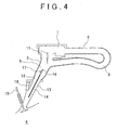
- FIG. 1 to FIG. 4 illustrate a first embodiment of an intake control device for an internal combustion engine according to the present invention.
- the intake control device of the first embodiment has a surge tank 1, and an intake pipe (which is hereinafter referred to as "main intake pipe") 3 extending obliquely leftward and downward from a lower side of the surge tank 1 and connected to an intake port 2.
- the main intake pipe 3 extends generally straight from the surge tank 1 to the intake port 2 and connected to the intake port 2 such that it is aligned with the intake port 2.
- the main intake pipe 3 and the intake port 2 together form an intake passage (hereinafter “main intake passage”) 5 that extends from the surge tank 1 to a combustion chamber 4.
- main intake passage hereinafter “main intake passage”
- the intake control device also has an intake pipe (hereinafter “sub-intake pipe”) 6 extending from the right side of the surge tank 1 and connected to the main intake pipe 3.
- An intake passage (hereinafter “sub-intake passage”) 8 extending from the surge tank 1 to the main intake pipe 3 (that is, the main intake passage 5) is formed by the sub-intake pipe 6.
- the length of the sub-intake passage 8 from the surge tank 1 to the main intake passage 5 is longer than that of the main intake passage 5 from the surge tank 1 to a connection point S between the sub-intake passage 8 and the main intake passage 5.
- the passage cross-sectional area of the sub-intake passage 8 is smaller than that of the main intake passage 5 from the surge tank 1 to the connection point S between the sub-intake passage 8 and the main intake passage 5.
- a valve (hereinafter “intake passage length-changing valve”) 11 having a plate-shaped valve element 10 rotatable about a pivot shaft 9 to open and close the main intake pipe 3 is disposed upstream of the point S (which is hereinafter referred to as "intake pipe connection point") where the sub-intake pipe 6 is connected to the main intake pipe 3.
- the intake passage length-changing valve 11 shown in FIG. 1 and FIG. 2 has closed the main intake pipe 3 and the intake passage length-changing valve 11 shown in FIG. 3 and FIG. 4 has opened the main intake pipe 3.
- a partition 14 that partitions an internal space in the main intake passage 5 along the axis of the main intake passage 5 into two intake passages 12 and 13 is disposed downstream of the intake pipe connection point S in the main intake passage 5.
- the partition 14 is a flat plate and disposed such that the width direction of a plane including the plate is perpendicular or generally perpendicular to the central axis of the combustion chamber 4.
- a valve which is hereinafter referred to as "tumble control valve" 17 having a plate-shaped valve element 16 rotatable about a pivot shaft 15 attached to the end of the partition 14 to open and close the partitioned intake passage 12, is disposed.
- the tumble control valve 17 shown in FIG. 2 and FIG. 4 has opened the partitioned intake passage 12.
- the plate-shaped valve element 16 of the tumble control valve 17 is parallel to the partition 14, and, in particular, on the same or generally the same plane as the partition 14 as shown in FIG. 2 and FIG. 4 .
- the sub-intake pipe 6 is connected to the main intake pipe 3 such that the axis of the sub-intake pipe 6 immediately upstream of the point where it is connected to the main intake pipe 3 is perpendicular or generally perpendicular to the width direction of a plane including the partition 14. Also, the sub-intake pipe 6 is connected to the main intake pipe 3 from a direction perpendicular or generally perpendicular to the partition 14.
- the partitioned intake passage 12, which is opened and closed by the tumble control valve 17, is the partitioned intake passage on the side opposite the side on which the sub-intake pipe 6 is connected to the main intake pipe 3 with respect to the partition 14. In FIG 1 , a fuel injection valve 18 and an intake valve 19 are also shown.
- the inertia charging effect which is achieved at a lower engine speed, is highest when the intake passage length-changing valve 11 and the tumble control valve 17 are in the state shown in FIG. 1 , second highest when in the state shown in FIG 2 , third highest when in the state shown in FIG. 3 , and lowest when in the state shown in FIG. 4 .
- the length and passage cross-sectional area of the main intake passage 5 and the length and passage cross-sectional area of the sub-intake passage 8 are set to be the longest and the smallest when the intake passage length-changing valve 11 and the tumble control valve 17 are in the state shown in FIG.
- a higher inertia charging effect may be achieved at a low engine speed. That is, as the length of the intake passage is longer and the cross-sectional area of the intake passage is smaller, synchronous engine speed regarding so-called intake pulsation will be lower. Therefore, when the engine speed is the lowest, the highest inertia charging effect may be achieved by the intake passage length-changing valve 11 and the tumble control valve 17 being controlled to the state shown in FIG 1 , and when the engine speed is the second lowest, the highest inertia charging effect may be achieved by the intake passage length-changing valve 11 and the tumble control valve 17 being controlled to the state shown in FIG 2 .
- the highest inertia charging effect may be achieved by the intake passage length-changing valve 11 and the tumble control valve 17 being controlled to the state shown in FIG 3
- the highest inertia charging effect may be achieved by the intake passage length-changing valve 11 and the tumble control valve 17 being controlled to the state shown in FIG. 4 .
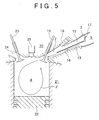
- FIG. 5 a cylinder head 20, a cylinder block 21, a piston 22, an exhaust valve 23, an exhaust port 24, spark plug 25 are also shown.
- the control of the intake passage length-changing valve 11 and the control of the tumble control valve 17 are next described.
- the internal combustion engine performs lean-burn combustion, in which the air-fuel mixture in the combustion chamber 4 is burned at an air-fuel ratio higher than the stoichiometric air-fuel ratio (lean air-fuel ratio) when the engine operating condition is in a range X shown in FIG.
- the internal combustion engine performs a stoichiometric combustion, in which the air-fuel mixture in the combustion chamber 4 is burned at an air-fuel ratio equal to or close to the stoichiometric air-fuel ratio when the engine operating condition is in the range Y shown in FIG. 6 (that is, the engine load is not equal to or close to full load, the engine speed is relatively high, and the engine load is in a relatively high range).
- the intake passage length-changing valve 11 and the tumble control valve 17 are controlled as described below.
- the intake passage length-changing valve 11 is controlled to keep the main intake passage 5 open and the tumble control valve 17 is controlled to keep the partitioned intake passage 12 open as shown in FIG. 4 . That is, when the internal combustion engine performs stoichiometric combustion, the engine load is relatively high and therefore the amount of air to be drawn into the combustion chamber 4 (which is hereinafter referred to as "intake air amount") must be increased to a relatively large level.
- intake air amount the intake air amount
- the intake passage length-changing valve 11 is controlled to keep the main intake passage 5 open and the tumble control valve 17 is controlled to keep the partitioned intake passage 12 closed as shown in FIG. 3 . That is, the internal combustion engine performs lean-burn combustion, the engine load is relatively low and therefore the intake air amount does not have to be increased very much but good combustion must be achieved with a small amount of fuel.
- the intake passage length-changing valve 11 and the tumble control valve 17 are controlled as described above, a tumble flow of air (air-fuel mixture) is formed in the combustion chamber 4, as shown in FIG. 5 , because air flows into the combustion chamber 4 only through the partitioned intake passage 12. Then, mixing of fuel and air is promoted, and good combustion is achieved with a small amount of fuel.
- the intake passage length-changing valve 11 and the tumble control valve 17 are controlled as described below.
- the intake passage length-changing valve 11 is controlled to keep the main intake passage 5 closed and the tumble control valve 17 is controlled to keep the partitioned intake passage 12 closed as shown FIG 1 . That is, when the internal combustion engine performs full-load combustion, the engine load is very high and therefore the intake air amount must be increased as much as possible.
- the intake air amount may be vary large by the shape of the intake passage (the shape of the intake passage through which air flows from the surge tank 1 into the combustion chamber 4) being as narrow and long as possible because of the relation with the engine speed.
- the intake passage length-changing valve 11 is controlled to keep the main intake passage 5 closed and the tumble control valve 17 is controlled to keep the partitioned intake passage 12 open as shown in FIG 2 . That is, when the internal combustion engine performs full-load combustion, the engine load is very high and therefore the intake air amount must be increased as much as possible.
- the engine operating condition is in the low-intermediate speed range Z2
- an inertia charging effect may be achieved and the amount of air may be very large by the shape of the intake passage being the second narrowest and longest because of the relation with the engine speed. Therefore, when the intake passage length-changing valve 11 and the tumble control valve 17 are controlled as described above, a very large amount of air flows into the combustion chamber 4 by an inertia charging effect because the shape of the intake passage is at its second narrowest and longest.
- the intake passage length-changing valve 11 is controlled to keep the main intake passage 5 open and the tumble control valve 17 is controlled to keep the partitioned intake passage 12 closed as shown in FIG. 3 . That is, when the internal combustion engine performs full-load combustion, the engine load is very high and therefore the intake air amount must be increased as much as possible.
- the engine operating condition is in the intermediate-high speed range Z3
- an inertia charging effect may be achieved and the amount of air may be very large by the shape of the intake passage being the third narrowest and longest because of the relation with the engine speed. Therefore, when the intake passage length-changing valve 11 and the tumble control valve 17 are controlled as described above, a very large amount of air flows into the combustion chamber 4 by an inertia charging effect because the shape of the intake passage is at its third narrowest and longest.
- the intake passage length-changing valve 11 is controlled to keep the main intake passage 5 open and the tumble control valve 17 is controlled to keep the partitioned intake passage 12 open as shown in FIG 4 . That is, when the internal combustion engine performs full-load combustion, the engine load is very high and therefore the intake air amount must be increased as much as possible.
- the intake air amount may be very large by the shape of the intake passage being as wide and short as possible because of the relation with the engine speed. Therefore, when the intake passage length-changing valve 11 and the tumble control valve 17 are controlled as described above, because the shape of the intake passage can be the widest and shortest, a very large amount of air flows into the combustion chamber 4 by an inertia charging effect.
- the tumble control valve 17 When the main intake passage 5, the sub-intake passage 8, the intake passage length-changing valve 11, and the tumble control valve 17 are constituted and arranged as in this embodiment, a higher inertia charging effect may be achieved because the volume of the intake passage from the surge tank 1 to the combustion chamber 4 hardly changes.
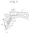
- FIG 7 to FIG 10 illustrate the second embodiment.
- the main intake passage 5 and the sub-intake passage 8 are the same as those in the first embodiment.
- the partition 14, the intake passage length-changing valve 11, and the tumble control valve 17 are different from those in the first embodiment.
- the intake passage length-changing valve 11 in this embodiment which is disposed upstream of the intake pipe connection point (the point where the sub-intake pipe 6 is connected to the main intake pipe 3) S in the main intake pipe 3 and rotatable about the pivot shaft 9 to open and close the main intake pipe 3, has two plate-shaped valve elements 10A and 10B which are rotatable independently through different ranges about the pivot shaft 9 as a common pivot shaft.
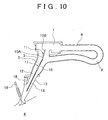
- the intake passage length-changing valve 11 shown in FIG. 7 and FIG. 8 has closed the main intake pipe 3 and the intake passage length-changing valve 11 shown in FIG. 9 and FIG. 10 has opened the main intake pipe 3.
- a partition 14 for partitioning an internal space in the main intake passage 5 along the axis of the main intake passage 5 into two partitioned intake passages is disposed downstream of the intake pipe connection point S in the main intake passage 5.
- the partition 14 is a flat plate and disposed such that the width direction of a plane including the plate is perpendicular or generally perpendicular to the central axis of the combustion chamber 4. Also, the partition 14 extends toward the surge tank 1 such that a periphery of the valve element 10A of the intake passage length-changing valve 11 is adjacent to the surge tank 1 side end of the partition 14 when the intake passage length-changing valve 11 is in the state shown in FIG 7 .
- the plate-shaped valve element 16 of the tumble control valve 17 is disposed such that it is rotatable about a pivot shaft 15 attached to an intermediate portion of the partition 14, in particular, a part of the partition 14 slightly on the surge tank 1 side from the center thereof, to open and close the partitioned intake passage 12.
- the tumble control valve 17 shown in FIG. 7 and FIG. 9 has closed the partitioned intake passage 12, and the tumble control valve 17 shown in FIG. 8 and FIG. 10 has opened the partitioned intake passage 12.
- the plate-shaped valve element 16 of the tumble control valve 17 is parallel to the partition 14, and, in particular, on the same or generally the same plane as the partition 14 as shown in FIG 8 and FIG. 10 .
- the partitioned intake passage 12, which is opened and closed by the tumble control valve 17, is the partitioned intake passage on the side opposite the side on which the sub-intake pipe 6 is connected to the main intake pipe 3 with respect to the partition 14.
- the intake passage length-changing valve 11 When the intake passage length-changing valve 11 is in the state shown in FIG. 10 , it is parallel to the partition 14 and, in particular, on the same plane or generally the same plane as the partition 14.
- the shape of the intake passage (the shape of the intake passage, through which air flows from the surge tank 1 into the combustion chamber 4) is the narrowest and longest when the intake passage length-changing valve 11 and the tumble control valve 17 are in the state shown in FIG. 7 , second narrowest and longest when in the state shown in FIG. 8 , third narrowest and longest when in the state shown in FIG. 9 , and the widest and shortest when in the state shown in FIG. 10 .
- the intake passage length-changing valve 11 is controlled to keep the main intake passage 5 open and the tumble control valve 17 is controlled to keep the partitioned intake passage 12 open as shown in FIG. 10 .
- the intake air amount (the amount of air to be drawn into the combustion chamber 4) must be increased to a relatively large level.
- the intake passage length-changing valve 11 and the tumble control valve 17 are controlled as described above, because air flows into the combustion chamber 4 through the entire main intake passage 5, pumping loss is reduced and the intake air amount can be relatively large.
- the intake passage length-changing valve 11 is controlled to keep the main intake passage 5 open and the tumble control valve 17 is controlled to keep the partitioned intake passage 12 closed as shown in FIG. 9 . That is, the internal combustion engine performs lean-burn combustion, the intake air amount does not have to be increased very much but good combustion must be achieved with a small amount of fuel.
- the intake passage length-changing valve 11 and the tumble control valve 17 are controlled as described above, because air flows into the combustion chamber 4 only through the partitioned intake passage 12, a tumble flow of air (air-fuel mixture) is formed in the combustion chamber 4. Then, mixing of fuel and air is promoted, and good combustion is achieved with a small amount of fuel.
- the intake passage length-changing valve 11 is controlled to keep the main intake passage 5 closed and the tumble control valve 17 is controlled to keep the partitioned intake passage 12 closed as shown FIG. 7 .
- the intake air amount must be increased as much as possible.
- the engine operating condition is in the low speed range Z1
- an inertia charging effect may be achieved and the intake air amount may be vary large by the shape of the intake passage (the shape of the intake passage through which air flows from the surge tank 1 into the combustion chamber 4) being as narrow and long as possible because of the relation with the engine speed. Therefore, when the intake passage length-changing valve 11 and the tumble control valve 17 are controlled as described above, a very large amount of air flows into the combustion chamber 4 by an inertia charging effect because of the shape of the intake passage is at its narrowest and longest.
- the intake passage length-changing valve 11 is controlled to keep the main intake passage 5 closed and the tumble control valve 17 is controlled to keep the partitioned intake passage 12 open as shown in FIG. 8 .
- the intake air amount must be increased as much as possible.
- the engine operating condition is in the low-intermediate speed range Z2
- an inertia charging effect may be achieved and the intake air amount may be very large by the shape of the intake passage being the second narrowest and longest because of the relation with the engine speed. Therefore, when the intake passage length-changing valve 11 and the tumble control valve 17 are controlled as described above, a very large amount of air flows into the combustion chamber 4 by an inertia charging effect because the shape of the intake passage is at its be the second narrowest and longest.
- the intake passage length-changing valve 11 is controlled to keep the main intake passage 5 open and the tumble control valve 17 is controlled to keep the partitioned intake passage 12 closed as shown in FIG. 9 .
- the intake air amount must be increased as much as possible.
- the engine operating condition is in the intermediate-high speed range Z3
- an inertia charging effect may be achieved and the amount of air may be very large by the shape of the intake passage being the third narrowest and longest because of the relation with the engine speed. Therefore, when the intake passage length-changing valve 11 and the tumble control valve 17 are controlled as described above, a very large amount of air flows into the combustion chamber 4 by an inertia charging effect because the intake passage is at its third narrowest and longest.
- the intake passage length-changing valve 11 is controlled to keep the main intake passage 5 open and the tumble control valve 17 is controlled to keep the partitioned intake passage 12 open as shown in FIG. 10 .
- the intake air amount must be increased as much as possible.
- the intake passage length-changing valve 11 and the tumble control valve 17 are controlled as described above, a very large amount of air flows into the combustion chamber 4 by an inertia charging effect because the shape of the intake passage is at its widest and shortest.
- the main intake passage 5, the sub-intake passage 8, the intake passage length-changing valve 11, and the tumble control valve 17 are constituted and arranged as in this embodiment, a higher inertia charging effect may be achieved because the volume of the intake passage from the surge tank 1 to the combustion chamber 4 hardly changes.
- the region designated by a reference symbol W1 is a region where the volume of the intake passage is changed largely (so-called dead volume) when the intake passage length-changing valve 11 and the tumble control valve 17 are in the state shown in FIG 1 in the first embodiment, but such a region where the volume of the intake passage is changed largely is not formed in the second embodiment as shown in FIG. 7 .
- a higher inertia charging effect may be achieved.
- FIG. 11 to FIG. 14 illustrate the third embodiment.
- the main intake passage 5 the sub-intake passage 8, the intake passage length-changing valve 11, and the partition 14 are the same as those in the second embodiment.
- the tumble control valve 17 is different from those in the second embodiment.
- the plate-shaped valve element 16 of the tumble control valve 17 is disposed such that it is rotatable about a pivot shaft 15 attached to a part of the partition 14 adjacent to the combustion chamber side end thereof to open and close the partitioned intake passage 12.
- the tumble control valve 17 shown in FIG. 11 and FIG 13 has closed the partitioned intake passage 12, and the tumble control valve 17 shown in FIG. 12 and FIG. 14 has opened the partitioned intake passage 12.
- the plate-shaped valve element 16 of the tumble control valve 17 is parallel to the partition 14, and, in particular, on the same or generally the same plane as the partition 14 as shown in FIG. 12 and FIG. 14 .
- the intake passage length-changing valve 11 shown in FIG. 11 and FIG. 12 has closed the main intake pipe 3 and the intake passage length-changing valve 11 shown in FIG. 13 and FIG. 14 has opened the main intake pipe 3.
- the partitioned intake passage 12, which is opened and closed by the tumble control valve 17, is on the side opposite the side on which the sub-intake pipe 6 is connected to the main intake pipe 3 with respect to the partition 14.
- the shape of the intake passage (the shape of the intake passage, through which air flows from the surge tank 1 into the combustion chamber 4) is the narrowest and longest when the intake passage length-changing valve 11 and the tumble control valve 17 are in the state shown in FIG. 11 , second narrowest and longest when in the state shown in FIG. 12 , third narrowest and longest when in the state shown in FIG. 13 , and the widest and shortest when in the state shown in FIG. 14 .
- the intake passage length-changing valve 11 is controlled to keep the main intake passage 5 open and the tumble control valve 17 is controlled to keep the partitioned intake passage 12 open as shown in FIG. 14 .
- the intake air amount (the amount of air to be drawn into the combustion chamber 4) must be increased to a relatively large level.
- pumping loss is reduced and the intake air amount can be relatively large because air flows into the combustion chamber 4 through the entire main intake passage 5.
- the intake passage length-changing valve 11 is controlled to keep the main intake passage 5 open and the tumble control valve 17 is controlled to keep the partitioned intake passage 12 closed as shown in FIG. 13 . That is, the internal combustion engine performs lean-burn combustion, the intake air amount does not have to be increased very much but good combustion must be achieved with a small amount of fuel.
- the intake passage length-changing valve 11 and the tumble control valve 17 are controlled as described above, a tumble flow of air (air-fuel mixture) is formed in the combustion chamber 4 because air flows into the combustion chamber 4 only through the partitioned intake passage 12. Then, mixing of fuel and air is promoted, and good combustion is achieved with a small amount of fuel.
- the intake passage length-changing valve 11 is controlled to keep the main intake passage 5 closed and the tumble control valve 17 is controlled to keep the partitioned intake passage 12 closed as shown FIG. 11 .
- the intake air amount must be increased as much as possible.
- the engine operating condition is in the low speed range Z1
- an inertia charging effect may be achieved and the intake air amount may be vary large by the shape of the intake passage (the shape of the intake passage through which air flows from the surge tank 1 into the combustion chamber 4) being as narrow and long as possible. Therefore, when the intake passage length-changing valve 11 and the tumble control valve 17 are controlled as described above, because the shape of the intake passage is at its narrowest and longest, a very large amount of air flows into the combustion chamber 4 by an inertia charging effect.
- the intake passage length-changing valve 11 is controlled to keep the main intake passage 5 closed and the tumble control valve 17 is controlled to keep the partitioned intake passage 12 open as shown in FIG. 12 .
- the intake air amount must be increased as much as possible.
- the engine operating condition is in the low-intermediate speed range Z2
- an inertia charging effect may be achieved and the intake air amount may be very large by the shape of the intake passage being the second narrowest and longest because of the relation with the engine speed. Therefore, when the intake passage length-changing valve 11 and the tumble control valve 17 are controlled as described above, a very large amount of air flows into the combustion chamber 4 by an inertia charging effect because the shape of the intake passage is at its second narrowest and longest.
- the intake passage length-changing valve 11 is controlled to keep the main intake passage 5 open and the tumble control valve 17 is controlled to keep the partitioned intake passage 12 closed as shown in FIG. 13 .
- the intake air amount must be increased as much as possible.
- the engine operating condition is in the intermediate-high speed range Z3
- an inertia charging effect may be achieved and the amount of air may be very large by the shape of the intake passage being the third narrowest and longest because of the relation with the engine speed. Therefore, when the intake passage length-changing valve 11 and the tumble control valve 17 are controlled as described above, because the shape of the intake passage is at its third narrowest and longest, a very large amount of air flows into the combustion chamber 4 by an inertia charging effect.
- the intake passage length-changing valve 11 is controlled to keep the main intake passage 5 open and the tumble control valve 17 is controlled to keep the partitioned intake passage 12 open as shown in FIG. 14 .
- the intake air amount must be increased as much as possible.
- the intake passage length-changing valve 11 and the tumble control valve 17 are controlled as described above, a very large amount of air flows into the combustion chamber 4 due to the inertia charging effect because the shape of the intake passage is at its widest and shortest.
- the main intake passage 5, the sub-intake passage 8, the intake passage length-changing valve 11, and the tumble control valve 17 are constituted and arranged as in this embodiment, a higher inertia charging effect may be achieved because the volume of the intake passage from the surge tank 1 to the combustion chamber 4 hardly changes.
- the region W1 which is formed when the intake passage length-changing valve 11 and the tumble control valve 17 are in the state shown in FIG. 1 in the first embodiment and in which the volume of the intake passage is changed largely, is not formed in the third embodiment as shown in FIG. 11 , a higher inertia charging effect can be achieved.
- a stronger tumble flow of air (air-fuel mixture) is formed in the combustion chamber 4.
- the tumble control valve 17 is attached to an intermediate part of the partition 14 as in the second embodiment shown in FIG. 7 to FIG. 10 , a space W2 downstream of the tumble control valve 17 in the partitioned intake passage 12 is relatively large when the partitioned intake passage 12 is closed by the tumble control valve 17, as can be understood with reference to FIG. 7 , and air accumulates in the partitioned intake passage 12 downstream of the tumble control valve 17 while the intake valve 19 is closed.
- the tumble control valve 17 is attached to a part of the partition 14 adjacent to the combustion chamber 4 side end thereof as in the third embodiment, the space downstream of the tumble control valve 17 in the partitioned intake passage 12 is relatively small when the partitioned intake passage 12 is closed by the tumble control valve 17 as can be understood with reference to FIG. 11 and only a small amount of air is accumulated in the partitioned intake passage 12 downstream of the tumble control valve 17 while the intake valve 19 is closed.
- the amount of air which drawn into the combustion chamber 4 from the space downstream of the tumble control valve 17 in the partitioned intake passage 12 when the intake valve 19 is opened is very small and a much larger amount of air is drawn into the combustion chamber 4 through the partitioned intake passage 13, which is not closed by the tumble control valve 17. Therefore, a stronger tumble flow of air (air-fuel mixture) is formed in the combustion chamber 4.
- the intake passage length-changing valve 11 and the tumble control valve 17 when the intake passage length-changing valve 11 and the tumble control valve 17 are switched from the state shown in FIG. 2 to the state shown in FIG. 3 , the intake passage length-changing valve 11 and the tumble control valve 17 may be simultaneously switched from the state shown in FIG. 2 to the state shown in FIG. 3 .
- the tumble control valve 17 may be switched from the state shown in FIG. 2 to the state shown in FIG. 3 after the intake passage length-changing valve 11 is switched from the state shown in FIG. 2 to the state shown in FIG. 3 . That is, the intake passage length-changing valve 11 and the tumble control valve 17 may be switched from the state shown in FIG. 2 through the state shown in FIG. 4 to the state shown in FIG. 3 .
- the intake passage length-changing valve 11 and the tumble control valve 17 when the intake passage length-changing valve 11 and the tumble control valve 17 are switched from the state shown in FIG. 8 to the state shown in FIG. 9 , the intake passage length-changing valve 11 and the tumble control valve 17 may be switched from the state shown in FIG. 8 through the state shown in FIG. 10 to the state shown in FIG. 9 .
- the intake passage length-changing valve 11 and the tumble control valve 17 when the intake passage length-changing valve 11 and the tumble control valve 17 are switched from the state shown in FIG. 12 to the state shown in FIG. 13 , the intake passage length-changing valve 11 and the tumble control valve 17 may be switched from the state shown in FIG. 12 through the state shown in FIG. 14 to the state shown in FIG. 13 .
- the intake passage length-changing valve 11 and the tumble control valve 17 when the intake passage length-changing valve 11 and the tumble control valve 17 are switched from the state shown in FIG. 3 to the state shown in FIG. 2 , the intake passage length-changing valve 11 and the tumble control valve 17 may be simultaneously switched from the state shown in FIG. 3 to the state shown in FIG. 3 .
- the intake passage length-changing valve 11 may be switched from the state shown in FIG. 3 to the state shown in FIG. 2 after the tumble control valve 17 is switched from the state shown in FIG. 3 to the state shown in FIG. 2 . That is, the intake passage length-changing valve 11 and the tumble control valve 17 may be switched from the state shown in FIG. 3 through the state shown in FIG. 4 to the state shown in FIG. 2 .
- the intake passage length-changing valve 11 and the tumble control valve 17 when the intake passage length-changing valve 11 and the tumble control valve 17 are switched from the state shown in FIG. 9 to the state shown in FIG. 8 , the intake passage length-changing valve 11 and the tumble control valve 17 may be switched from the state shown in FIG. 9 through the state shown in FIG. 10 to the state shown in FIG. 8 .
- the intake passage length-changing valve 11 and the tumble control valve 17 when the intake passage length-changing valve 11 and the tumble control valve 17 are switched from the state shown in FIG. 13 to the state shown in FIG. 12 , the intake passage length-changing valve 11 and the tumble control valve 17 may be switched from the state shown in FIG. 13 through the state shown in FIG. 14 to the state shown in FIG. 12 .
- a high inertia charging effect can be achieved regardless of the operating condition of the tumble control valve.
Landscapes
- Engineering & Computer Science (AREA)
- Chemical & Material Sciences (AREA)
- Combustion & Propulsion (AREA)
- Mechanical Engineering (AREA)
- General Engineering & Computer Science (AREA)
- Characterised By The Charging Evacuation (AREA)
- Electrical Control Of Air Or Fuel Supplied To Internal-Combustion Engine (AREA)
Abstract
Claims (13)
- Dispositif de commande d'admission de moteur à combustion interne qui comprend un réservoir d'égalisation de pression (1) ; un premier passage d'admission (5) qui s'étend depuis le réservoir d'égalisation de pression (1) et est relié à une chambre de combustion (4) ; un deuxième passage d'admission (8) qui s'étend depuis le réservoir d'égalisation de pression (1) et est relié au premier passage d'admission (5) ; une chicane (14), disposée dans le premier passage d'admission (5), qui divise un espace interne dans le premier passage d'admission (5) en aval du point de raccordement le long d'un axe du premier passage d'admission (5) afin de former deux passages d'admission divisés (12, 13) ; une soupape de commande de rotation (17) qui ouvre et ferme un des passages d'admission divisés (12), de l'air admis dans la chambre de combustion à travers le passage d'admission divisé ouvert (13) formant un écoulement en rotation quand la soupape de commande de rotation (17) ferme un des passages d'admission divisés (12), la longueur du deuxième passage d'admission (8) depuis le réservoir d'égalisation de pression (1) jusqu'au premier passage d'admission (5) est plus longue que la longueur du premier passage d'admission (5) depuis le réservoir d'égalisation de pression (1) jusqu'au point de raccordement ; et
la section du deuxième passage d'admission (8) est plus petite que la section du premier passage d'admission (5) depuis le réservoir d'égalisation de pression (1) jusqu'au point de raccordement, le dispositif de commande d'admission étant caractérisé en ce que :une soupape de changement de longueur de passage d'admission (11) est prévue en amont d'un point de raccordement où le deuxième passage d'admission (8) se raccorde au premier passage d'admission (5), laquelle soupape ouvre et ferme le premier passage d'admission (5). - Dispositif de commande d'admission de moteur à combustion interne selon la revendication 1, dans lequel le point de raccordement est plus près du réservoir d'égalisation de pression (1) que de la chambre de combustion (4).
- Dispositif de commande d'admission de moteur à combustion interne selon la revendication 2, dans lequel le point de raccordement est adjacent au réservoir d'égalisation de pression (1).
- Dispositif de commande d'admission de moteur à combustion interne selon l'une quelconque des revendications 1 à 3, dans lequel le deuxième passage d'admission (8) est relié au premier passage d'admission (5) à partir d'une direction globalement perpendiculaire à la chicane (14), et la soupape de commande de rotation (17) ouvre et ferme le passage d'admission divisé (12) formé sur le côté opposé au côté sur lequel le deuxième passage d'admission (8) est relié au premier passage d'admission (5) par rapport à la chicane (14).
- Dispositif de commande d'admission de moteur à combustion interne selon l'une quelconque des revendications 1 à 4, dans lequel la soupape de commande de rotation (17) est fixée sur la chicane (14) et peut tourner autour d'un axe de pivotement (15) qui est fixé sur la chicane (14).
- Dispositif de commande d'admission de moteur à combustion interne selon la revendication 5, dans lequel la soupape de commande de rotation (17) a un élément de soupape en forme de plaque (16) qui peut tourner autour de l'axe de pivotement (15), et l'élément de soupape en forme de plaque (16) de la soupape de commande de rotation (17) est parallèle à la chicane (14) quand la soupape de commande de rotation (17) a ouvert l'un des passages d'admission divisés (12).
- Dispositif de commande d'admission de moteur à combustion interne selon la revendication 5 ou 6, dans lequel l'axe de pivotement (15) de la soupape de commande de rotation (17) est fixé sur la chicane (14) au niveau d'une extrémité de la chicane (14) qui est sont près de la chambre de combustion, et l'élément de soupape en forme de plaque (16) de la soupape de commande de rotation (17) est dans ou près du même plan que la chicane (14) quand la soupape de commande de rotation (17) a ouvert le passage d'admission divisé (12).
- Dispositif de commande d'admission de moteur à combustion interne selon l'une quelconque des revendications 1 à 7, dans lequel la soupape de changement de longueur de passage d'admission (11) a un élément de soupape en forme de plaque (10), et l'élément de soupape en forme de plaque (10) de la soupape de changement de longueur de passage d'admission (11) est dans ou près du même plan que la chicane (14) quand la soupape de changement de longueur de passage d'admission (11) a ouvert le premier passage d'admission (5).
- Dispositif de commande d'admission de moteur à combustion interne selon la revendication 8, dans lequel une périphérie sur le côté de combustion de l'élément de soupape en forme de plaque (10) de la soupape de changement de longueur de passage d'admission (11) est adjacent à l'extrémité du côté réservoir d'égalisation de pression de la chicane (14) quand la soupape de changement de longueur de passage d'admission (11) a ouvert le premier passage d'admission (5).
- Dispositif de commande d'admission de moteur à combustion interne selon la revendication 9, dans lequel la soupape de changement de longueur de passage d'admission (11) a deux éléments de soupape en forme de plaque (10A, 10B) pouvant tourner de manière indépendante sur différentes plages autour de deux axes de pivotement adjacents (9) ou un axe de pivotement commun (9), et une périphérie d'un des éléments de soupape en forme de plaque (10A) de la soupape de changement de longueur de passage d'admission (11) est adjacente à l'extrémité du côté réservoir d'égalisation de pression de la chicane (14) et une périphérie de l'autre élément de soupape en forme de plaque (10B) de la soupape de changement de longueur de passage d'admission (11) est adjacente à une face d'extrémité sur le côté réservoir d'égalisation de pression du deuxième passage d'admission (8) relié au premier passage d'admission (5) quand la soupape de changement de longueur de passage d'admission (11) a fermé le premier passage d'admission (5).
- Dispositif de commande d'admission de moteur à combustion interne selon l'une quelconque des revendications 1 à 10, dans lequel la longueur et la section de passage du premier passage d'admission (5) et la longueur et la section de passage du deuxième passage d'admission (8) sont établies de telle sorte que de l'air est admis dans la chambre de combustion (4) à travers le premier passage d'admission (5) à l'aide d'un effet de charge par inertie quand la vitesse de moteur est plus grande qu'une vitesse de moteur prédéterminée et que de l'air est admis dans la chambre de combustion (4) à travers le deuxième passage d'admission (8) à l'aide d'un effet de charge par inertie quand la vitesse de moteur est plus faible qu'une vitesse de moteur prédéterminée.
- Dispositif de commande d'admission de moteur à combustion interne selon l'une quelconque des revendications 1 à 11, dans lequel la soupape de changement de longueur de passage d'admission (11) maintient le premier passage d'admission (5) ouvert et la soupape de commande de rotation (17) maintient le passage d'admission divisé (12) ouvert quand la charge de moteur est inférieure à une charge de moteur prédéterminée dans une plage de charge de moteur telle que le moteur à combustion interne fonctionne à une charge inférieure à la pleine charge ou près de la pleine charge et le moteur à combustion interne exécute une combustion stoechiométrique dans laquelle le mélange air-carburant dans la chambre de combustion est brûlé à un rapport air-carburant égal ou proche du rapport air-carburant théorique, la soupape de changement de longueur de passage d'admission (11) maintient le premier passage d'admission (5) ouvert et la soupape de commande de rotation (17) maintient un des passages d'admission divisés (12) fermé quand la charge de moteur est plus forte qu'une charge de moteur prédéterminée dans une plage de charge de moteur telle que le moteur à combustion interne fonctionne à une charge inférieure à la pleine charge ou près de la pleine charge et le moteur à combustion interne exécute une combustion à mélange pauvre dans laquelle le mélange air-carburant dans la chambre de combustion est brûlé à un rapport air-carburant plus grand que le rapport air-carburant théorique, le fonctionnement de la soupape de changement de longueur de passage d'admission (11) et le fonctionnement de la soupape de commande de rotation (17) sont commandés en fonction de la vitesse de moteur quand la charge de moteur est égale à ou près de la pleine charge.
- Dispositif de commande d'admission de moteur à combustion interne selon l'une quelconque des revendications 1 à 12, dans lequel, dans le cas où la condition de fonctionnement du moteur à combustion interne est divisée en une condition de fonctionnement à vitesse réduite, une condition de fonctionnement à vitesse intermédiaire faible, une condition de fonctionnement à vitesse intermédiaire élevée, et une condition de fonctionnement à grande vitesse dans l'ordre de vitesse de moteur croissante, la soupape de changement de longueur de passage d'admission (11) maintient le premier passage d'admission (5) fermé et la soupape de commande de rotation (17) maintient l'un des passages d'admission divisés (12) fermé quand la charge de moteur est égale à ou près de la pleine charge et le moteur à combustion interne est dans la condition de fonctionnement à vitesse réduite, la soupape de changement de longueur de passage d'admission (11) maintient le premier passage d'admission (5) fermé et la soupape de commande de rotation (17) maintient le passage d'admission divisé (12) ouvert quand la charge de moteur est égale à ou près de la pleine charge et le moteur à combustion interne est dans la condition de fonctionnement à vitesse intermédiaire faible, la soupape de changement de longueur de passage d'admission (11) maintient le premier passage d'admission (5) ouvert et la soupape de commande de rotation (17) maintient un des passages d'admission divisés (12) fermé quand la charge de moteur est égale à ou près de la pleine charge et le moteur à combustion interne est dans la condition de fonctionnement à vitesse intermédiaire élevée, et la soupape de changement de longueur de passage d'admission (11) maintient le premier passage d'admission (5) ouvert et la soupape de commande de rotation (17) maintient le passage d'admission divisé (12) ouvert quand la charge de moteur est égale à ou près de la pleine charge et le moteur à combustion interne est dans la condition de fonctionnement à grande vitesse.
Applications Claiming Priority (2)
| Application Number | Priority Date | Filing Date | Title |
|---|---|---|---|
| JP2006129978 | 2006-05-09 | ||
| PCT/IB2007/001156 WO2007132311A2 (fr) | 2006-05-09 | 2007-05-04 | Dispositif de commande d'admission pour moteur à combustion interne |
Publications (3)
| Publication Number | Publication Date |
|---|---|
| EP2018471A2 EP2018471A2 (fr) | 2009-01-28 |
| EP2018471B1 true EP2018471B1 (fr) | 2011-01-26 |
| EP2018471B8 EP2018471B8 (fr) | 2011-03-30 |
Family
ID=38694270
Family Applications (1)
| Application Number | Title | Priority Date | Filing Date |
|---|---|---|---|
| EP07734473A Ceased EP2018471B8 (fr) | 2006-05-09 | 2007-05-04 | Dispositif de commande d'admission pour moteur à combustion interne |
Country Status (5)
| Country | Link |
|---|---|
| US (1) | US8127742B2 (fr) |
| EP (1) | EP2018471B8 (fr) |
| CN (1) | CN101389838A (fr) |
| DE (1) | DE602007012229D1 (fr) |
| WO (1) | WO2007132311A2 (fr) |
Families Citing this family (13)
| Publication number | Priority date | Publication date | Assignee | Title |
|---|---|---|---|---|
| ATE535698T1 (de) * | 2008-03-11 | 2011-12-15 | Yamaha Motor Co Ltd | Motor mit einlasssteuerungsvorrichtung |
| US7802555B2 (en) | 2008-03-18 | 2010-09-28 | Yamaha Hatsudoki Kabushiki Kaisha | Intake control device for an engine |
| US8151754B2 (en) * | 2008-09-16 | 2012-04-10 | Kawasaki Jukogyo Kabushiki Kaisha | Air-intake duct and air-intake structure |
| KR20100050782A (ko) * | 2008-11-06 | 2010-05-14 | 현대자동차주식회사 | 가변 흡기 시스템 |
| FR2954406A1 (fr) * | 2009-12-17 | 2011-06-24 | Renault Sa | Dispositif d'admission pour moteur a combustion interne |
| CN102364070A (zh) * | 2011-10-31 | 2012-02-29 | 长城汽车股份有限公司 | 增压发动机进气系统 |
| DE102012005103A1 (de) * | 2012-03-14 | 2013-09-19 | Gm Global Technology Operations, Llc | Luftansaugvorrichtung für eine Brennkraftmaschine eines Fahrzeugs |
| EP2843224B1 (fr) * | 2013-08-30 | 2018-11-28 | MANN+HUMMEL GmbH | Canal d'air d'alimentation pour moteur à combustion interne |
| JP6334990B2 (ja) * | 2014-03-31 | 2018-05-30 | ダイハツ工業株式会社 | 内燃機関 |
| KR101575285B1 (ko) * | 2014-05-19 | 2015-12-22 | 현대자동차 주식회사 | 가변 밸브가 적용된 가변 흡기 시스템 |
| JP2016041915A (ja) * | 2014-08-18 | 2016-03-31 | トヨタ自動車株式会社 | 内燃機関 |
| JP6327180B2 (ja) * | 2015-03-12 | 2018-05-23 | トヨタ自動車株式会社 | 内燃機関 |
| JP7481910B2 (ja) * | 2020-06-03 | 2024-05-13 | 株式会社Subaru | エンジン、および隔壁プレートの断面形状の設定方法 |
Family Cites Families (22)
| Publication number | Priority date | Publication date | Assignee | Title |
|---|---|---|---|---|
| DE3704717A1 (de) | 1986-02-25 | 1987-08-27 | Volkswagen Ag | Mehrzylinder-brennkraftmaschine mit mitteln zur drallerhoehung |
| JPH0742637A (ja) * | 1993-07-28 | 1995-02-10 | Yamaha Motor Co Ltd | 4サイクルエンジンの吸気装置 |
| JPH07119472A (ja) * | 1993-10-19 | 1995-05-09 | Fuji Heavy Ind Ltd | エンジンの吸気装置 |
| JP3244908B2 (ja) | 1993-12-29 | 2002-01-07 | ヤマハ発動機株式会社 | エンジンの吸気制御装置 |
| JPH07197823A (ja) * | 1993-12-29 | 1995-08-01 | Yamaha Motor Co Ltd | V型多気筒エンジンの吸気制御装置 |
| JP3308754B2 (ja) * | 1995-02-15 | 2002-07-29 | ヤマハ発動機株式会社 | エンジンの排気再循環装置 |
| CN2259494Y (zh) | 1995-11-14 | 1997-08-13 | 财团法人工业技术研究院 | 具有旁通气流控制阀的进气系统 |
| JP3677876B2 (ja) * | 1996-07-12 | 2005-08-03 | 日産自動車株式会社 | エンジンの点火時期制御装置 |
| JP3248439B2 (ja) | 1996-12-13 | 2002-01-21 | 三菱自動車工業株式会社 | 筒内噴射型内燃機関の制御装置 |
| JP3250475B2 (ja) * | 1996-12-13 | 2002-01-28 | 三菱自動車工業株式会社 | 筒内噴射型内燃機関の制御装置 |
| US6484690B2 (en) | 1999-01-06 | 2002-11-26 | Hitachi, Ltd. | Control equipment for internal combustion engines |
| DE19954455A1 (de) * | 1999-11-12 | 2001-05-17 | Fev Motorentech Gmbh | Stelleinheit zur Erzeugung variabler Ladungsbewegungen im Zylinder einer Kolbenbrennkraftmaschine |
| JP2002070566A (ja) | 2000-08-24 | 2002-03-08 | Hitachi Ltd | 一体成形タンブル制御バルブを有する吸気装置 |
| DE10163284B4 (de) * | 2000-12-27 | 2005-12-15 | Hyundai Motor Company | Verfahren zum Herstellen eines Variabel-Wirbelströmungs-Erzeugungs-Einlasskanals |
| AT5136U1 (de) * | 2001-02-08 | 2002-03-25 | Avl List Gmbh | Drallverstellbarer einlasskanal mit zumindest einer in längsrichtung verlaufenden trennwand |
| JP3987400B2 (ja) * | 2002-09-06 | 2007-10-10 | 株式会社日立製作所 | 可変動弁装置を備えた内燃機関の燃料供給装置および方法 |
| JP4045915B2 (ja) * | 2002-10-03 | 2008-02-13 | 日産自動車株式会社 | 内燃機関の吸気装置 |
| US6827054B2 (en) * | 2002-12-06 | 2004-12-07 | Daimlerchrysler Corporation | Integrated inlet manifold tuning valve and charge motion control device for internal combustion engines |
| JP2004293485A (ja) | 2003-03-28 | 2004-10-21 | Mazda Motor Corp | 火花点火式エンジンの吸気装置 |
| JP3829818B2 (ja) * | 2003-04-18 | 2006-10-04 | 日産自動車株式会社 | 内燃機関の吸気装置 |
| JP2006283696A (ja) * | 2005-04-01 | 2006-10-19 | Toyota Motor Corp | 内燃機関の吸気装置 |
| US7128050B1 (en) * | 2005-06-16 | 2006-10-31 | Toyota Jidosha Kabushiki Kaisha | Air intake apparatus for internal combustion engine |
-
2007
- 2007-05-04 DE DE602007012229T patent/DE602007012229D1/de active Active
- 2007-05-04 CN CNA2007800062561A patent/CN101389838A/zh active Pending
- 2007-05-04 WO PCT/IB2007/001156 patent/WO2007132311A2/fr not_active Ceased
- 2007-05-04 US US12/086,974 patent/US8127742B2/en not_active Expired - Fee Related
- 2007-05-04 EP EP07734473A patent/EP2018471B8/fr not_active Ceased
Also Published As
| Publication number | Publication date |
|---|---|
| US20090272355A1 (en) | 2009-11-05 |
| DE602007012229D1 (de) | 2011-03-10 |
| US8127742B2 (en) | 2012-03-06 |
| EP2018471B8 (fr) | 2011-03-30 |
| WO2007132311A2 (fr) | 2007-11-22 |
| EP2018471A2 (fr) | 2009-01-28 |
| WO2007132311A3 (fr) | 2008-02-28 |
| CN101389838A (zh) | 2009-03-18 |
Similar Documents
| Publication | Publication Date | Title |
|---|---|---|
| EP2018471B1 (fr) | Dispositif de commande d'admission pour moteur à combustion interne | |
| EP0867610B1 (fr) | Système d'admission d'air pour moteur à combustion interne | |
| EP2218886B1 (fr) | Structure de ligne d'échappement d'un moteur multicylindre | |
| EP2039908B1 (fr) | Moteur à deux temps à balayage stratifié | |
| JP4840248B2 (ja) | 内燃機関の吸気制御装置 | |
| JP6394621B2 (ja) | エンジンの過給装置 | |
| US20100037853A1 (en) | Intake system for an internal combustion engine | |
| JP4525441B2 (ja) | 内燃機関 | |
| EP1111218A2 (fr) | Valve de commande du mouvement d'air dans le collecteur d'admission supérieur | |
| EP1834070B1 (fr) | Dispositif d'aspiration pour moteur a combustion interne | |
| US10724425B2 (en) | Cylinder head of internal combustion engine | |
| JPH0416605B2 (fr) | ||
| EP1705351B1 (fr) | Dispositif de contrôle d'un moteur multicylindre | |
| JP2010031685A (ja) | 火花点火式内燃機関 | |
| JPH10231729A (ja) | 内燃機関の吸気装置 | |
| JP4548323B2 (ja) | 過給機付きエンジンの吸気制御装置 | |
| JP2004308441A (ja) | 内燃機関の吸気装置 | |
| JPH0415939Y2 (fr) | ||
| JP2001214745A (ja) | ピストンバルブ式2サイクルエンジン | |
| JP2007138899A (ja) | 内燃機関の吸気通路構造 | |
| KR20040003143A (ko) | 차량용 흡기매니폴드 | |
| JPH051554A (ja) | エンジンの燃焼室構造 | |
| JPH0629562B2 (ja) | エンジンの吸気装置 | |
| US20170107956A1 (en) | Variable intake system | |
| JPH01224421A (ja) | エンジンの吸気装置 |
Legal Events
| Date | Code | Title | Description |
|---|---|---|---|
| PUAI | Public reference made under article 153(3) epc to a published international application that has entered the european phase |
Free format text: ORIGINAL CODE: 0009012 |
|
| 17P | Request for examination filed |
Effective date: 20081209 |
|
| AK | Designated contracting states |
Kind code of ref document: A2 Designated state(s): AT BE BG CH CY CZ DE DK EE ES FI FR GB GR HU IE IS IT LI LT LU LV MC MT NL PL PT RO SE SI SK TR |
|
| AX | Request for extension of the european patent |
Extension state: AL BA HR MK RS |
|
| DAX | Request for extension of the european patent (deleted) | ||
| RBV | Designated contracting states (corrected) |
Designated state(s): DE FR |
|
| GRAP | Despatch of communication of intention to grant a patent |
Free format text: ORIGINAL CODE: EPIDOSNIGR1 |
|
| GRAS | Grant fee paid |
Free format text: ORIGINAL CODE: EPIDOSNIGR3 |
|
| GRAA | (expected) grant |
Free format text: ORIGINAL CODE: 0009210 |
|
| AK | Designated contracting states |
Kind code of ref document: B1 Designated state(s): DE FR |
|
| REF | Corresponds to: |
Ref document number: 602007012229 Country of ref document: DE Date of ref document: 20110310 Kind code of ref document: P |
|
| REG | Reference to a national code |
Ref country code: DE Ref legal event code: R096 Ref document number: 602007012229 Country of ref document: DE Effective date: 20110310 |
|
| RAP2 | Party data changed (patent owner data changed or rights of a patent transferred) |
Owner name: TOYOTA JIDOSHA KABUSHIKI KAISHA |
|
| PLBE | No opposition filed within time limit |
Free format text: ORIGINAL CODE: 0009261 |
|
| STAA | Information on the status of an ep patent application or granted ep patent |
Free format text: STATUS: NO OPPOSITION FILED WITHIN TIME LIMIT |
|
| 26N | No opposition filed |
Effective date: 20111027 |
|
| REG | Reference to a national code |
Ref country code: DE Ref legal event code: R097 Ref document number: 602007012229 Country of ref document: DE Effective date: 20111027 |
|
| REG | Reference to a national code |
Ref country code: DE Ref legal event code: R084 Ref document number: 602007012229 Country of ref document: DE Effective date: 20130312 |
|
| REG | Reference to a national code |
Ref country code: FR Ref legal event code: PLFP Year of fee payment: 10 |
|
| REG | Reference to a national code |
Ref country code: FR Ref legal event code: PLFP Year of fee payment: 11 |
|
| REG | Reference to a national code |
Ref country code: FR Ref legal event code: PLFP Year of fee payment: 12 |
|
| PGFP | Annual fee paid to national office [announced via postgrant information from national office to epo] |
Ref country code: DE Payment date: 20190423 Year of fee payment: 13 |
|
| PGFP | Annual fee paid to national office [announced via postgrant information from national office to epo] |
Ref country code: FR Payment date: 20190410 Year of fee payment: 13 |
|
| REG | Reference to a national code |
Ref country code: DE Ref legal event code: R119 Ref document number: 602007012229 Country of ref document: DE |
|
| PG25 | Lapsed in a contracting state [announced via postgrant information from national office to epo] |
Ref country code: FR Free format text: LAPSE BECAUSE OF NON-PAYMENT OF DUE FEES Effective date: 20200531 |
|
| PG25 | Lapsed in a contracting state [announced via postgrant information from national office to epo] |
Ref country code: DE Free format text: LAPSE BECAUSE OF NON-PAYMENT OF DUE FEES Effective date: 20201201 |