EP1167937A1 - Dispositif d'entrée pour des types de mouvements figurés ( et son ) par des déviations et leur vitesse ( optique ) - Google Patents
Dispositif d'entrée pour des types de mouvements figurés ( et son ) par des déviations et leur vitesse ( optique ) Download PDFInfo
- Publication number
- EP1167937A1 EP1167937A1 EP01113891A EP01113891A EP1167937A1 EP 1167937 A1 EP1167937 A1 EP 1167937A1 EP 01113891 A EP01113891 A EP 01113891A EP 01113891 A EP01113891 A EP 01113891A EP 1167937 A1 EP1167937 A1 EP 1167937A1
- Authority
- EP
- European Patent Office
- Prior art keywords
- input device
- light
- emitting devices
- parts
- movements
- Prior art date
- Legal status (The legal status is an assumption and is not a legal conclusion. Google has not performed a legal analysis and makes no representation as to the accuracy of the status listed.)
- Granted
Links
Images



Classifications
-
- G—PHYSICS
- G01—MEASURING; TESTING
- G01L—MEASURING FORCE, STRESS, TORQUE, WORK, MECHANICAL POWER, MECHANICAL EFFICIENCY, OR FLUID PRESSURE
- G01L5/00—Apparatus for, or methods of, measuring force, work, mechanical power, or torque, specially adapted for specific purposes
- G01L5/22—Apparatus for, or methods of, measuring force, work, mechanical power, or torque, specially adapted for specific purposes for measuring the force applied to control members, e.g. control members of vehicles, triggers
-
- G—PHYSICS
- G06—COMPUTING OR CALCULATING; COUNTING
- G06F—ELECTRIC DIGITAL DATA PROCESSING
- G06F3/00—Input arrangements for transferring data to be processed into a form capable of being handled by the computer; Output arrangements for transferring data from processing unit to output unit, e.g. interface arrangements
- G06F3/01—Input arrangements or combined input and output arrangements for interaction between user and computer
- G06F3/03—Arrangements for converting the position or the displacement of a member into a coded form
- G06F3/033—Pointing devices displaced or positioned by the user, e.g. mice, trackballs, pens or joysticks; Accessories therefor
- G06F3/0346—Pointing devices displaced or positioned by the user, e.g. mice, trackballs, pens or joysticks; Accessories therefor with detection of the device orientation or free movement in a three-dimensional [3D] space, e.g. 3D mice, 6-DOF [six degrees of freedom] pointers using gyroscopes, accelerometers or tilt-sensors
Definitions
- the invention relates to an actuatable by hand movements Input device for commanding machine and / or computer aided Control operations for kinematic movements a real or virtual multi-part object with Force-moment sensor, with the linear displacements in shape translational movements towards each other vertical axes of a spatial, right-angled Coordinate system and / or rotary deflections in the form of rotary Movements around these three axes are recorded and commanded Movements of the object to be controlled are implemented.
- the invention also relates to possible uses of the Input device.
- Force-torque sensors of this type are made, for example DE 199 37 307 A1, DE 36 11 336 C2 and EP 0 240 023 B1 are known.
- Force-torque sensors housed in an input device
- Force-torque sensors can be linear displacements and / or rotary deflections, namely three translational ones Movements in the direction of the three perpendicular to each other standing axes (X, Y, Z) of a spatially rectangular coordinate system and three rotary movements around it capture three axes and directly into translational and rotary Movements or speeds of a to be controlled
- X, Y, Z standing axes
- three rotary movements around it capture three axes and directly into translational and rotary Movements or speeds of a to be controlled
- Implement entire object For example, machines, Robots, manipulators or similar systems as well 3D computer graphics can be controlled.
- Modern computers are more and more able to handle complex Execute 3D motion controls in real time. The manipulation of these movements and possibly related Sound changes are therefore human Control feelings and experiences.
- US 57 57 360 A is a manual actuated input device for controlling a virtual object known on a computer screen.
- it can Object itself according to the movement of the egg-shaped and hand-held input device, or it can agreed movement patterns of the input device on parts of the virtual object.
- the input device used is based on the principle of an accelerometer, of movements made in predetermined patterns of the entire input device inserted in one hand recognizable accelerations and acceleration patterns closes, which are detected to the on-screen displayed object one of the respective acceleration or motion characteristic assigned to the respective acceleration pattern let it come.
- This known input device that only for control or animation more virtual Objects, but not real for control or animation Objects, e.g.
- the object of the invention is an input device of the type mentioned in such a way that kinematic Targeted control and animation operations of objects and can be carried out intuitively. With those to be controlled or objects to be animated all about human-like robots or computer-generated ones virtual living beings, with a high control or variety of animation with great accuracy of the desired control or animation variant achieved shall be.
- the task is thereby solved that the commanded individual linear displacements and / or rotary deflections of the force-torque sensor kinematic movement patterns determined in a transformative way of parts of the consequently manipulable or animatable real or virtual object as Coupling are assigned and that the commanded speeds of the relevant linear displacements and / or rotary deflections of the force-torque sensor additionally can be evaluated as kinematic coupling assignment.
- the Individual movements of the kinematics to be controlled are so transformed like you would in a similar way from a puppeteer knows who manipulates a puppet.
- Advantageous uses of the input device after the invention exist in machine or computer-controlled Objects that are movable and / or movable as a whole Objects or living things are reproduced, whereby Parts of the respective reproduced object or living being, e.g. the arms, legs, torso and head of one Living beings to be controlled with regard to their kinematics Form parts of the object. It is also a use for computer-controlled animation operations of the objects useful.
- the input device according to the invention is not only for motion control of object parts can be used alone. Much more can advantageously be used in addition to motion control sounds and / or music of any kind combined from object parts and / or be varied. For example, this would be mean that when controlling a higher speed of the Input device on the part of the operator tones, e.g.
- the combination can be considered e.g. an 8-bit sensor resolution of 512 ( ⁇ 256) speed levels and 512 ( ⁇ 256) tone / noise changes with motion control a very large variety of combinations allow.
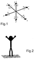
- the six possible movement components are shown in FIG. which are to be recorded with an input device.
- the input device shown as an example in Fig. 21 and Fig. 22 with force-moment sensor is used to perceive these directions of movement able and records all linear displacements and twisting deflections, like those of a human Hand generated in the form of forces and moments can to control an object and / or parts of an object.
- the possible linear displacements therefore run in both directions of the three coordinate axes X, Y each provided with arrowheads and Z of a right-angled spatial coordinate system, while the turning deflections, i.e. around the respective coordinate axes X, Y and Z generated moment vectors A, B and C, indicated by part circles provided with arrowheads are.
- Those with the input device, e.g. that according to Fig. 21 and Fig. 22 measured forces and moments are directly in translatory and rotary movements or speeds of the individual machine or computer controlled object parts implemented.
- the related pictogram-like, not specifically shown Representation is similar to that in Fig. 9, but with the Movement would be faster.
- a slow rotary movement transverse to the running direction i.e. a slow positive rotation around the X direction causes the object nods its head forward, as in the pictogram-like representation of a human Living being is indicated in Fig. 14.
- a fast rotary movement transverse to the direction of travel i.e. a rapid positive rotation around the X direction causes the object bends the torso, as in the pictogram-like Representation of a human being in Fig. 15 is indicated.
- a slow rotary movement transverse to the running direction i.e. a slow negative rotation around the X direction causes the object nods its head backwards, as in the pictogram-like representation of a human Living being is indicated in Fig. 16.
- a slow rotation around the direction of travel i.e. a slow positive rotation around the Y direction causes the object is nodding to the right, as in the pictogram-like representation of a human being is indicated in Fig.17.
- a quick rotation around the direction of travel i.e. a rapid positive rotation around the Y direction causes the object bends the body of the object to the right executes, as in the pictogram-like representation of a human being is indicated in Fig. 18.
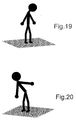
- a slow rotation around the direction of travel i.e. a slow negative rotation around the Y direction, causes the object nods to the left, as in the pictogram-like representation of a human being is indicated in Fig. 19.
- a quick rotation around the direction of travel i.e. a rapid negative rotation around the Y direction causes the object bends the body of the object to the left executes, as in the pictogram-like representation of a human being is indicated in Fig.20.
- a slow rotation around the object-body axis i.e. a slow positive rotation around the Z direction
- a rapid rotation around the object-body axis i.e. a rapid positive rotation around the Z direction causes the object jumps to the right.
- a slow rotation around the object-body axis i.e. a slow negative rotation around the Z direction causes the object turns left.
- a rapid rotation around the object-body axis i.e. a quick negative rotation around the Z direction, causes that the object turns to the left.
- To the latter movements are not characteristic of their own pictogram-like representations of a human Living being attached.
- FIG. 21 shows an input device 1 with a force-torque sensor in Form of an opto-electronic shown schematically in Fig. 22 Arrangement.
- this shows Input device 1 in the embodiment shown circular cylindrical control cap 8 with a slightly curved User interface 9, which is partially cut open in Fig. 21 is, so that part of the structure shown schematically of a schematically indicated force-torque sensor in Form of the opto-electronic arrangement can be seen.
- Arrangement are six light emitting devices 2-1 to 2-6, preferably in the form of six light emitting Diodes arranged in one plane.
- the light emitting Facilities 2-1 through 2-6 is at a fixed distance each assigned a slit diaphragm 3-1 to 3-6.
- neighboring ones Slit diaphragms in a cylindrical ring 3 with respect their main direction of expansion against each other by 90 ° staggered so that, for example, the Slit diaphragm 3-1 horizontal and the two neighboring ones Slit diaphragms 3-2 and 3-6 are aligned vertically.
- Fig. 22 there are six position sensitive photosensitive detectors 4-1 to 4-6 in a cylindrical ring 5 with respect to the associated Slit diaphragms 3-1 to 3-6 arranged accordingly. Furthermore, the ring 5 with the six position sensitive Detectors 4-1 to 4-6 firmly on the inside of the cylindrical control cap 8 of the input device 1 attached.
- Bracket device 6 can in a practical embodiment for example also as a stationary disc be executed, the diameter of which is approximately the outer diameter of the position-sensitive detectors 4-1 to 4-6 Ring 5 corresponds and which above or below the ring 5th can be arranged.
- the coil springs 7 ensure that the detectors 4-1 to 4-6 bearing ring 5 with respect to the control cap 8 the stationary arrangement of the light-emitting diodes 2-1 to 2-6 and the slit diaphragm ring permanently assigned to them 3 in the direction of the three axes X, Y, Z one right-angled spatial coordinate system (see Fig. 1) and is movable about these three axes and after each linear displacement or turning deflection back to its original position returns.
- the six light emitting diodes 2-1 to 2-6 are the same Angular distances from each other, i.e. at an angle of 60 °, arranged in one level and assign them alternately this level horizontally and vertically aligned slit diaphragms 3-1 to 3-6.
- the axes of the individual position sensitive Detectors 4-1 to 4-6 always perpendicular to the slot diaphragms assigned to them 3-1 to 3-6 aligned.
Landscapes
- Engineering & Computer Science (AREA)
- Physics & Mathematics (AREA)
- General Physics & Mathematics (AREA)
- General Engineering & Computer Science (AREA)
- Theoretical Computer Science (AREA)
- Human Computer Interaction (AREA)
- Position Input By Displaying (AREA)
Applications Claiming Priority (2)
| Application Number | Priority Date | Filing Date | Title |
|---|---|---|---|
| DE10029173A DE10029173A1 (de) | 2000-06-19 | 2000-06-19 | Verfahren und Anordnung zum Kommandieren von Steuerungsoperationen für kinematische Bewegungen eines Objekts unter Verwendung eines von Hand betätigbaren Eingabegerätes |
| DE10029173 | 2000-06-19 |
Publications (2)
| Publication Number | Publication Date |
|---|---|
| EP1167937A1 true EP1167937A1 (fr) | 2002-01-02 |
| EP1167937B1 EP1167937B1 (fr) | 2003-06-11 |
Family
ID=7645616
Family Applications (1)
| Application Number | Title | Priority Date | Filing Date |
|---|---|---|---|
| EP01113891A Expired - Lifetime EP1167937B1 (fr) | 2000-06-19 | 2001-06-08 | Dispositif d'entrée pour des types de mouvements figurés ( et son ) par des déviations et leur vitesse ( optique ) |
Country Status (3)
| Country | Link |
|---|---|
| US (1) | US6891526B2 (fr) |
| EP (1) | EP1167937B1 (fr) |
| DE (2) | DE10029173A1 (fr) |
Families Citing this family (47)
| Publication number | Priority date | Publication date | Assignee | Title |
|---|---|---|---|---|
| US7749089B1 (en) | 1999-02-26 | 2010-07-06 | Creative Kingdoms, Llc | Multi-media interactive play system |
| US7878905B2 (en) | 2000-02-22 | 2011-02-01 | Creative Kingdoms, Llc | Multi-layered interactive play experience |
| US6761637B2 (en) | 2000-02-22 | 2004-07-13 | Creative Kingdoms, Llc | Method of game play using RFID tracking device |
| US7445550B2 (en) | 2000-02-22 | 2008-11-04 | Creative Kingdoms, Llc | Magical wand and interactive play experience |
| US7066781B2 (en) | 2000-10-20 | 2006-06-27 | Denise Chapman Weston | Children's toy with wireless tag/transponder |
| AU2002331786A1 (en) | 2001-08-31 | 2003-03-18 | The Board Of Regents Of The University And Community College System, On Behalf Of The University Of | Coordinated joint motion control system |
| DE10146470B4 (de) * | 2001-09-21 | 2007-05-31 | 3Dconnexion Gmbh | Auswahl von Software- und Hardwarefunktionen mit einem Kraft-/Momentensensor |
| DE10158776B4 (de) * | 2001-11-30 | 2004-05-13 | 3Dconnexion Gmbh | Anordnung zum Erfassen von Relativbewegungen oder Relativpositionen zweier Objekte |
| US6967566B2 (en) | 2002-04-05 | 2005-11-22 | Creative Kingdoms, Llc | Live-action interactive adventure game |
| US20070066396A1 (en) | 2002-04-05 | 2007-03-22 | Denise Chapman Weston | Retail methods for providing an interactive product to a consumer |
| AU2003229632A1 (en) * | 2002-04-10 | 2003-10-20 | Fraunhofer-Gesellschaft Zur Forderung Der Angewandten Forschung E.V. | Input device, system and method for controlling objects that can be displayed on a display |
| DE10247287A1 (de) * | 2002-04-10 | 2003-10-30 | Fraunhofer Ges Forschung | Eingabegerät, System und Verfahren zur Steuerung von auf einer Anzeige darstellbaren Objekten |
| US7674184B2 (en) | 2002-08-01 | 2010-03-09 | Creative Kingdoms, Llc | Interactive water attraction and quest game |
| JP4160843B2 (ja) * | 2003-02-24 | 2008-10-08 | アルプス電気株式会社 | 力覚付与型入力装置 |
| US9446319B2 (en) | 2003-03-25 | 2016-09-20 | Mq Gaming, Llc | Interactive gaming toy |
| US7194337B2 (en) * | 2003-10-31 | 2007-03-20 | Hewlett-Packard Development Company, Lp | Agent-based operation of a robotic device |
| US7239301B2 (en) | 2004-04-30 | 2007-07-03 | Hillcrest Laboratories, Inc. | 3D pointing devices and methods |
| PL1741088T3 (pl) | 2004-04-30 | 2012-08-31 | Hillcrest Lab Inc | Urządzenia wskazujące w przestrzeni swobodnej, z kompensacją nachylenia i usprawnioną użytecznością |
| US8629836B2 (en) | 2004-04-30 | 2014-01-14 | Hillcrest Laboratories, Inc. | 3D pointing devices with orientation compensation and improved usability |
| USD519569S1 (en) * | 2004-08-16 | 2006-04-25 | Namco Inc. | Inputting machine for computer game machine |
| US8137195B2 (en) | 2004-11-23 | 2012-03-20 | Hillcrest Laboratories, Inc. | Semantic gaming and application transformation |
| US7927216B2 (en) | 2005-09-15 | 2011-04-19 | Nintendo Co., Ltd. | Video game system with wireless modular handheld controller |
| US7942745B2 (en) | 2005-08-22 | 2011-05-17 | Nintendo Co., Ltd. | Game operating device |
| US8313379B2 (en) | 2005-08-22 | 2012-11-20 | Nintendo Co., Ltd. | Video game system with wireless modular handheld controller |
| JP4805633B2 (ja) | 2005-08-22 | 2011-11-02 | 任天堂株式会社 | ゲーム用操作装置 |
| JP4262726B2 (ja) | 2005-08-24 | 2009-05-13 | 任天堂株式会社 | ゲームコントローラおよびゲームシステム |
| US8870655B2 (en) | 2005-08-24 | 2014-10-28 | Nintendo Co., Ltd. | Wireless game controllers |
| US8308563B2 (en) | 2005-08-30 | 2012-11-13 | Nintendo Co., Ltd. | Game system and storage medium having game program stored thereon |
| US8157651B2 (en) | 2005-09-12 | 2012-04-17 | Nintendo Co., Ltd. | Information processing program |
| US8065060B2 (en) * | 2006-01-18 | 2011-11-22 | The Board Of Regents Of The University And Community College System On Behalf Of The University Of Nevada | Coordinated joint motion control system with position error correction |
| JP4530419B2 (ja) | 2006-03-09 | 2010-08-25 | 任天堂株式会社 | 座標算出装置および座標算出プログラム |
| JP4151982B2 (ja) | 2006-03-10 | 2008-09-17 | 任天堂株式会社 | 動き判別装置および動き判別プログラム |
| JP4684147B2 (ja) | 2006-03-28 | 2011-05-18 | 任天堂株式会社 | 傾き算出装置、傾き算出プログラム、ゲーム装置およびゲームプログラム |
| US8913003B2 (en) | 2006-07-17 | 2014-12-16 | Thinkoptics, Inc. | Free-space multi-dimensional absolute pointer using a projection marker system |
| USD603022S1 (en) * | 2007-01-15 | 2009-10-27 | Hansgrohe Ag | Kitchen or bath control |
| JP5127242B2 (ja) | 2007-01-19 | 2013-01-23 | 任天堂株式会社 | 加速度データ処理プログラムおよびゲームプログラム |
| US9176598B2 (en) | 2007-05-08 | 2015-11-03 | Thinkoptics, Inc. | Free-space multi-dimensional absolute pointer with improved performance |
| US7842875B2 (en) * | 2007-10-19 | 2010-11-30 | Sony Computer Entertainment America Inc. | Scheme for providing audio effects for a musical instrument and for controlling images with same |
| US9870021B2 (en) | 2009-04-15 | 2018-01-16 | SeeScan, Inc. | Magnetic manual user interface devices |
| WO2011146668A2 (fr) | 2010-05-18 | 2011-11-24 | Seektech, Inc. | Dispositifs d'interface utilisateur, appareil et procédés |
| EP3179330B1 (fr) | 2010-08-20 | 2020-03-18 | SeeScan, Inc. | Dispositif d'interface utilisateur avec détection magnétique |
| WO2012051357A1 (fr) | 2010-10-12 | 2012-04-19 | Mark Olsson | Dispositifs de manette de télécommande magnétiques |
| EP2665989B1 (fr) | 2010-11-08 | 2019-12-25 | SeeScan, Inc. | Dispositifs de type interface utilisateur et magnétiques à profil mince |
| EP3043231A1 (fr) | 2010-12-02 | 2016-07-13 | SeeScan, Inc. | Dispositif d'interface utilisateur détectée magnétiquement |
| US9678577B1 (en) | 2011-08-20 | 2017-06-13 | SeeScan, Inc. | Magnetic sensing user interface device methods and apparatus using electromagnets and associated magnetic sensors |
| WO2014164207A1 (fr) | 2013-03-12 | 2014-10-09 | Stryker Corporation | Ensemble capteur et procédé permettant de mesurer des forces et des couples |
| EP2997453B1 (fr) | 2013-05-17 | 2020-10-21 | SeeScan, Inc. | Dispositifs d'interface utilisateur |
Citations (3)
| Publication number | Priority date | Publication date | Assignee | Title |
|---|---|---|---|---|
| US5757360A (en) * | 1995-05-03 | 1998-05-26 | Mitsubishi Electric Information Technology Center America, Inc. | Hand held computer control device |
| DE19937307A1 (de) * | 1998-08-10 | 2000-02-17 | Deutsch Zentr Luft & Raumfahrt | Verfahren zum Auslösen von technischen Steueroperationen und/oder zum Auslösen der Ausführung von technischen Funktionen sowie Anordnung zur Durchführung des Verfahrens |
| WO2000014676A1 (fr) * | 1998-09-08 | 2000-03-16 | Gmd Forschungszentrum Informationstechnik Gmbh | Appareil d'entree pour signaux de commande servant a commander le deplacement d'un objet represente sur un dispositif d'affichage, et affichage graphique pourvu d'un tel appareil d'entree |
Family Cites Families (8)
| Publication number | Priority date | Publication date | Assignee | Title |
|---|---|---|---|---|
| US5222400A (en) * | 1985-12-18 | 1993-06-29 | Spaceball Technologies Incorporated | Force and torque converter |
| DE3611336A1 (de) | 1986-04-04 | 1987-10-15 | Deutsche Forsch Luft Raumfahrt | Kraft-drehmoment-fuehler |
| DE3611337A1 (de) * | 1986-04-04 | 1987-10-22 | Deutsche Forsch Luft Raumfahrt | In einer kunststoffkugel untergebrachte, opto-elektronische anordnung |
| US5589828A (en) * | 1992-03-05 | 1996-12-31 | Armstrong; Brad A. | 6 Degrees of freedom controller with capability of tactile feedback |
| DE69517423D1 (de) * | 1994-04-11 | 2000-07-13 | Peter Neltoft | Gerät zur manuellen steuerung der bewegung eines realen oder imaginären objektes |
| US5703623A (en) * | 1996-01-24 | 1997-12-30 | Hall; Malcolm G. | Smart orientation sensing circuit for remote control |
| US5923318A (en) * | 1996-04-12 | 1999-07-13 | Zhai; Shumin | Finger manipulatable 6 degree-of-freedom input device |
| US6072467A (en) * | 1996-05-03 | 2000-06-06 | Mitsubishi Electric Information Technology Center America, Inc. (Ita) | Continuously variable control of animated on-screen characters |
-
2000
- 2000-06-19 DE DE10029173A patent/DE10029173A1/de not_active Withdrawn
-
2001
- 2001-06-08 DE DE50100303T patent/DE50100303D1/de not_active Expired - Lifetime
- 2001-06-08 EP EP01113891A patent/EP1167937B1/fr not_active Expired - Lifetime
- 2001-06-19 US US09/883,361 patent/US6891526B2/en not_active Expired - Fee Related
Patent Citations (3)
| Publication number | Priority date | Publication date | Assignee | Title |
|---|---|---|---|---|
| US5757360A (en) * | 1995-05-03 | 1998-05-26 | Mitsubishi Electric Information Technology Center America, Inc. | Hand held computer control device |
| DE19937307A1 (de) * | 1998-08-10 | 2000-02-17 | Deutsch Zentr Luft & Raumfahrt | Verfahren zum Auslösen von technischen Steueroperationen und/oder zum Auslösen der Ausführung von technischen Funktionen sowie Anordnung zur Durchführung des Verfahrens |
| WO2000014676A1 (fr) * | 1998-09-08 | 2000-03-16 | Gmd Forschungszentrum Informationstechnik Gmbh | Appareil d'entree pour signaux de commande servant a commander le deplacement d'un objet represente sur un dispositif d'affichage, et affichage graphique pourvu d'un tel appareil d'entree |
Also Published As
| Publication number | Publication date |
|---|---|
| US6891526B2 (en) | 2005-05-10 |
| DE10029173A1 (de) | 2002-01-03 |
| EP1167937B1 (fr) | 2003-06-11 |
| DE50100303D1 (de) | 2003-07-17 |
| US20010053942A1 (en) | 2001-12-20 |
Similar Documents
| Publication | Publication Date | Title |
|---|---|---|
| EP1167937B1 (fr) | Dispositif d'entrée pour des types de mouvements figurés ( et son ) par des déviations et leur vitesse ( optique ) | |
| EP0979990B1 (fr) | Dispositif pour déclenchement d'operations techniques de contrôle et/ou de déclenchement d'execution des fonctions techniques | |
| DE69532536T2 (de) | Vorrichtung mit mechanischem eingang/ausgang für rechnersysteme mit einer schnittstelle für flexible langgestreckte gegenstände | |
| DE69513416T2 (de) | Steuereinrichtung mit einem bewegbaren steuerelement | |
| DE69632028T2 (de) | Verfahren und vorrichtung zur bereitstellung einer rauscharmen mechanischen eingabe/ausgabe mit grosser bandbreite für computer systeme | |
| AT511523B1 (de) | Vorrichtung zur räumlichen bewegung von personen | |
| EP0940651A2 (fr) | Appareil de mesure de coordonnée avec guide pour utilisateur | |
| DE19741730A1 (de) | Verfahren und Vorrichtung zur Ermittlung der Oberflächenkontur von Meßobjekten | |
| DE102019103557B4 (de) | Schwingungsanalysator und Schwingungsanalyseverfahren | |
| WO2010040505A1 (fr) | Simulateur de mouvement et d'orientation | |
| DE69710566T2 (de) | Vorrichtung zur interaktion und navigation in einer virtuellen umgebung | |
| WO1986003156A1 (fr) | Main prehensile pour manipulateur | |
| WO2018007075A1 (fr) | Système et procédé d'interaction | |
| WO1998007086A1 (fr) | Systeme de capteurs corporels | |
| EP3645919A2 (fr) | Dispositif et procédé de sélection de rapports dans des véhicules à moteur | |
| DE19952560A1 (de) | Verfahren zum Ein- und/oder Verstellen eines Sitzes, von Teilen des Sitzes und/oder von den Fahrer unterstützenden Vorrichtungen und Anordnung zur Durchführung des Verfahrens | |
| EP1431740A1 (fr) | Dispositif de mesure pour l'enregistrement sans contact des vibrations d'un objet | |
| DE60225137T2 (de) | Robotergeräte | |
| DE102004063975A1 (de) | Optoelektronische Anordnung zum Erfassen von Relativbewegungen oder Relativpositionen zweier Objekte und Methodik zum Design | |
| DE102016225797A1 (de) | Lidar-Sensor zur Erfassung eines Objektes | |
| DE4302434A1 (de) | Verfahren zur Bestimmung der Relativlage zweier Bauteile und Vorrichtung zur Durchführung des Verfahrens | |
| DE10325284A1 (de) | Multidimensionales Eingabegerät zur Navigation und Selektion von vituellen Objekten | |
| DE69905758T2 (de) | Vorrichtung zur bewegung einer last mit begrenztem ausschlag in einem bis sechs freiheitsgraden | |
| EP3645920A2 (fr) | Dispositif et procédé de sélection de rapports dans des véhicules à moteur | |
| DE4226661A1 (de) | Verfahren und Vorrichtung zur Bedienung elektronischer Musikinstrumente |
Legal Events
| Date | Code | Title | Description |
|---|---|---|---|
| PUAI | Public reference made under article 153(3) epc to a published international application that has entered the european phase |
Free format text: ORIGINAL CODE: 0009012 |
|
| AK | Designated contracting states |
Kind code of ref document: A1 Designated state(s): DE FR GB IT SE Kind code of ref document: A1 Designated state(s): AT BE CH CY DE DK ES FI FR GB GR IE IT LI LU MC NL PT SE TR |
|
| AX | Request for extension of the european patent |
Free format text: AL;LT;LV;MK;RO;SI |
|
| 17P | Request for examination filed |
Effective date: 20020626 |
|
| AKX | Designation fees paid |
Free format text: DE FR GB IT SE |
|
| 17Q | First examination report despatched |
Effective date: 20020912 |
|
| GRAH | Despatch of communication of intention to grant a patent |
Free format text: ORIGINAL CODE: EPIDOS IGRA |
|
| GRAH | Despatch of communication of intention to grant a patent |
Free format text: ORIGINAL CODE: EPIDOS IGRA |
|
| GRAA | (expected) grant |
Free format text: ORIGINAL CODE: 0009210 |
|
| AK | Designated contracting states |
Designated state(s): DE FR GB IT SE |
|
| REG | Reference to a national code |
Ref country code: GB Ref legal event code: FG4D Free format text: NOT ENGLISH |
|
| GBT | Gb: translation of ep patent filed (gb section 77(6)(a)/1977) | ||
| REG | Reference to a national code |
Ref country code: IE Ref legal event code: FG4D Free format text: GERMAN |
|
| REF | Corresponds to: |
Ref document number: 50100303 Country of ref document: DE Date of ref document: 20030717 Kind code of ref document: P |
|
| REG | Reference to a national code |
Ref country code: SE Ref legal event code: TRGR |
|
| REG | Reference to a national code |
Ref country code: IE Ref legal event code: FD4D |
|
| ET | Fr: translation filed | ||
| PLBE | No opposition filed within time limit |
Free format text: ORIGINAL CODE: 0009261 |
|
| STAA | Information on the status of an ep patent application or granted ep patent |
Free format text: STATUS: NO OPPOSITION FILED WITHIN TIME LIMIT |
|
| 26N | No opposition filed |
Effective date: 20040312 |
|
| PGFP | Annual fee paid to national office [announced via postgrant information from national office to epo] |
Ref country code: GB Payment date: 20130529 Year of fee payment: 13 Ref country code: SE Payment date: 20130607 Year of fee payment: 13 |
|
| PGFP | Annual fee paid to national office [announced via postgrant information from national office to epo] |
Ref country code: IT Payment date: 20130618 Year of fee payment: 13 Ref country code: FR Payment date: 20130618 Year of fee payment: 13 |
|
| REG | Reference to a national code |
Ref country code: DE Ref legal event code: R082 Ref document number: 50100303 Country of ref document: DE Representative=s name: WUESTHOFF & WUESTHOFF PATENT- UND RECHTSANWAEL, DE |
|
| REG | Reference to a national code |
Ref country code: DE Ref legal event code: R081 Ref document number: 50100303 Country of ref document: DE Owner name: GALILEO 2011, MC Free format text: FORMER OWNER: DEUTSCHES ZENTRUM FUER LUFT- UND RAUMFAHRT E.V., 51147 KOELN, DE Effective date: 20140324 Ref country code: DE Ref legal event code: R082 Ref document number: 50100303 Country of ref document: DE Representative=s name: WUESTHOFF & WUESTHOFF PATENT- UND RECHTSANWAEL, DE Effective date: 20140324 Ref country code: DE Ref legal event code: R082 Ref document number: 50100303 Country of ref document: DE Representative=s name: WUESTHOFF & WUESTHOFF, PATENTANWAELTE PARTG MB, DE Effective date: 20140324 |
|
| PG25 | Lapsed in a contracting state [announced via postgrant information from national office to epo] |
Ref country code: SE Free format text: LAPSE BECAUSE OF NON-PAYMENT OF DUE FEES Effective date: 20140609 |
|
| REG | Reference to a national code |
Ref country code: SE Ref legal event code: EUG |
|
| GBPC | Gb: european patent ceased through non-payment of renewal fee |
Effective date: 20140608 |
|
| REG | Reference to a national code |
Ref country code: FR Ref legal event code: ST Effective date: 20150227 |
|
| PG25 | Lapsed in a contracting state [announced via postgrant information from national office to epo] |
Ref country code: IT Free format text: LAPSE BECAUSE OF NON-PAYMENT OF DUE FEES Effective date: 20140608 |
|
| PG25 | Lapsed in a contracting state [announced via postgrant information from national office to epo] |
Ref country code: GB Free format text: LAPSE BECAUSE OF NON-PAYMENT OF DUE FEES Effective date: 20140608 Ref country code: FR Free format text: LAPSE BECAUSE OF NON-PAYMENT OF DUE FEES Effective date: 20140630 |
|
| PGFP | Annual fee paid to national office [announced via postgrant information from national office to epo] |
Ref country code: DE Payment date: 20200626 Year of fee payment: 20 |
|
| REG | Reference to a national code |
Ref country code: DE Ref legal event code: R071 Ref document number: 50100303 Country of ref document: DE |