EP1168056A2 - Appareil et méthode pour charger un film dans un appareil photo recyclable dans lequel le triage des appareils défectueux est différé - Google Patents
Appareil et méthode pour charger un film dans un appareil photo recyclable dans lequel le triage des appareils défectueux est différé Download PDFInfo
- Publication number
- EP1168056A2 EP1168056A2 EP01202123A EP01202123A EP1168056A2 EP 1168056 A2 EP1168056 A2 EP 1168056A2 EP 01202123 A EP01202123 A EP 01202123A EP 01202123 A EP01202123 A EP 01202123A EP 1168056 A2 EP1168056 A2 EP 1168056A2
- Authority
- EP
- European Patent Office
- Prior art keywords
- camera frame
- frame assemblies
- film
- defects
- pallets
- Prior art date
- Legal status (The legal status is an assumption and is not a legal conclusion. Google has not performed a legal analysis and makes no representation as to the accuracy of the status listed.)
- Withdrawn
Links
Images





Classifications
-
- G—PHYSICS
- G03—PHOTOGRAPHY; CINEMATOGRAPHY; ANALOGOUS TECHNIQUES USING WAVES OTHER THAN OPTICAL WAVES; ELECTROGRAPHY; HOLOGRAPHY
- G03B—APPARATUS OR ARRANGEMENTS FOR TAKING PHOTOGRAPHS OR FOR PROJECTING OR VIEWING THEM; APPARATUS OR ARRANGEMENTS EMPLOYING ANALOGOUS TECHNIQUES USING WAVES OTHER THAN OPTICAL WAVES; ACCESSORIES THEREFOR
- G03B17/00—Details of cameras or camera bodies; Accessories therefor
- G03B17/26—Holders for containing light sensitive material and adapted to be inserted within the camera
-
- Y—GENERAL TAGGING OF NEW TECHNOLOGICAL DEVELOPMENTS; GENERAL TAGGING OF CROSS-SECTIONAL TECHNOLOGIES SPANNING OVER SEVERAL SECTIONS OF THE IPC; TECHNICAL SUBJECTS COVERED BY FORMER USPC CROSS-REFERENCE ART COLLECTIONS [XRACs] AND DIGESTS
- Y10—TECHNICAL SUBJECTS COVERED BY FORMER USPC
- Y10T—TECHNICAL SUBJECTS COVERED BY FORMER US CLASSIFICATION
- Y10T29/00—Metal working
- Y10T29/53—Means to assemble or disassemble
- Y10T29/53022—Means to assemble or disassemble with means to test work or product
-
- Y—GENERAL TAGGING OF NEW TECHNOLOGICAL DEVELOPMENTS; GENERAL TAGGING OF CROSS-SECTIONAL TECHNOLOGIES SPANNING OVER SEVERAL SECTIONS OF THE IPC; TECHNICAL SUBJECTS COVERED BY FORMER USPC CROSS-REFERENCE ART COLLECTIONS [XRACs] AND DIGESTS
- Y10—TECHNICAL SUBJECTS COVERED BY FORMER USPC
- Y10T—TECHNICAL SUBJECTS COVERED BY FORMER US CLASSIFICATION
- Y10T29/00—Metal working
- Y10T29/53—Means to assemble or disassemble
- Y10T29/53313—Means to interrelatedly feed plural work parts from plural sources without manual intervention
- Y10T29/5337—Means to interrelatedly feed plural work parts from plural sources without manual intervention including assembly pallet
Definitions
- FIG. 1 illustrates one embodiment of a one-time-use camera 38.
- the camera 38 has a front cover 40, a back or back cover 42, and a frame unit 44 located between covers 40,42.
- a first film chamber 46 can contain a coreless film roll 34 or can have a film roll 34 held by a spool (not illustrated).
- a second film chamber 48 holds the film cartridge 22.
- the end of the filmstrip 32 is attached to a cartridge spool 50 within the canister 36.
- a thumbwheel 51 is joined to the cartridge spool 50.
- the frame unit 44 defines a film path (indicated by arrow 52 in Figure 2) along which the photographic filmstrip 32 travels as the filmstrip is advanced during use.
- the film path extends from the first film chamber 46, across an intermediate section 54 to the second film chamber 48.
- the intermediate section 54 includes an exposure area to which light is directed by an exposure unit 56.
- the exposure unit 56 includes sub-components such as a baffle, a lens system, a shutter, and a shutter release (not separately illustrated).
- the camera 38 can include a variety of other well-known camera features.
- the intermediate section 54 can include frame rails for supporting the film during camera use. Discrete camera constituents, such as, a flash system 47, a viewfinder, and a battery (not separately illustrated); can also be installed in the camera during assembly.
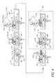
- pallets 16 are placed on the transporter 14, as indicated by arrows 109.
- Camera frame assemblies 18, that is, incomplete camera bodies, are then placed on respective pallets 16.
- Film cartridges 22 are placed on the pallets 16 with the camera frame assemblies 18.
- the two streams of pallets 16 are then brought together at the intersection 60.
- the order of the pallets 16 leaving the intersection 60 can be indeterminate. In other words, pallets 16 need not be provided by the two branches 58 at the same rate and the rate for each branch 58 can vary with time. This is likely, for example, if the steps of the first portion 20 of the system 10 are done manually.
- the film cartridge 22 is placed in the camera frame assembly 18 and the film is prewound out of the cartridge 22.
- a back 42 is then placed over the camera frame assembly 18 light tightly closing the camera frame assembly 18. The pallets 16 then leave the dark enclosure 28.
- the camera frame assemblies 18 are illustrated as bearing identifiers 110, in the form of bar-codes, at an early stage of the assembly process. Because the pallet bar-codes 108 are used to register information in the table, the camera identifiers 110 can be added whenever convenient. Defective cameras can be unnumbered, allowing continuous numbering of identifiers 110 of cameras packaged together for distribution. Monitoring is easier, since camera identifiers 110 can be provided in continuous blocks of numbers. The use of pallet bar-codes 108 also avoids any problems that could result from using film cartridge identifiers 112 to also identify cameras, such as possible confusion during reuse of film cartridges from defective cameras.
- the tabulated information about each pallet 16 is used in culling defective camera frame assemblies 18 at the completion of the process.
- This is a particularly advantageous approach, in that testing can be provided in the dark enclosure 28, without requiring access for culling of defective camera frame assemblies 18 at that time.
- Defective camera frame assemblies 18 can instead be tested for defects within the dark enclosure 28 and then be culled later after completing the assembly process.
- camera frame assemblies 18 can be tested and defective camera frame assemblies 18 can be easily removed, since it is easy to do so within the daylight environment.
- the first portion 20 of the system 10 can be simplified by eliminating the removal of defective camera frame assemblies 18.
- the camera frame assemblies 18 are tested, defects are recorded, and defective camera frame assemblies 18 are then allowed to continue through the assembly process for culling at the end.
- This approach also helps ensure the integrity of information in the controller. All pallets 16 enter and leave the system 10 only at the beginning and end, and all pallets 16 within the system 10 are continuously tracked in the table.
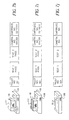
- the printer 116 prints defect indicators 120 (shown in Figures 5-6) on the outsides of camera frame assemblies 18, for use in classifying defective camera frame assemblies 18 for recycling of usable parts and monitoring of production.
- the printer 116 can optionally print an identifier 112 of the film cassette in the camera, on the outside of the camera.
- the cassette identifier 112 can be human or machine readable and is illustrated as a bar code.
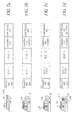
- the film cartridge 22 is placed in the camera frame assembly 18 by an installation device 134.
- the station 12 is illustrated in Figure 4, as also having a sensor 100 that detects whether the cartridge 22 is seated in the camera frame assembly 18. This test could provide a signal to the table in the controller 106, but is not illustrated as doing so in the figures.
- the installation device can be a simple pick-and-place device or can also provide additional functions, such as opening a light lock door of an Advanced Photo System 10TM film cartridge 22. These and other functions can also be provided by a combination of manual and automated stations.
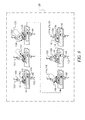
- the operation of the thumbwheel 51 is tested and test results are signalled to the controller 106, in the same manner as earlier described.
- the spool 50 of the film cartridge 22 is also tested for rotation in the second test.
- the direction of rotation of the disk 130 is indicated by an arrow 136.
- the thumbwheel 51 can be rotated in either direction in the first test. In both cases, the camera frame assembly 18 does not have a functioning anti-backup mechanism.
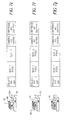
- Figures 7f-7h illustrate prewinding of the filmstrip 32 out of the canister 36 of the film cartridge 22 and into a film roll 34 and installation of the back cover 42.
- the camera frame assemblies 18 are printed within the dark enclosure 28 by a print head 136 of the printer 116.
- An inkjet print head 136 on a movable arm 138 is illustrated, but any type of printer 116 can be used. Labels can also be individually printed separately then attached (not illustrated). The latter approach is useful with complexly shaped camera bodies.
- defective camera frame assemblies 18 have printed defect indicators 120, such as codes for particular defects, as shown in Figure 5.
- the defect-free camera frame assemblies 18, in the embodiment shown in Figures 5-6 are printed with the identifier 112 of the film cartridge 22 before the camera frame assemblies 18 leave the dark enclosure 28.
- the filmstrip 32 of the film cartridge 22 is wound out of the canister in the second portion 24 of the system 10 in the dark enclosure 28. In doing so, a main part of the filmstrip 32 is wound into a film roll.
- the film roll is housed in the camera and is protected from light, in the finished camera, by the camera frame assembly 18.
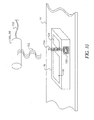
- Film cartridges 22 can be reclaimed from defective camera frame assemblies 18, but the filmstrip 32 must first be rewound into the canister 36 without exposing the filmstrip 32 to actinic light.
- the film rewinder 118 rewinds the filmstrips 32 of only the defective camera frame assemblies 18.
- the bar code of the pallet 16 is read and the value obtained is compared to the defect record 30, that is, a record in the table that indicates that the camera on a particular pallet 16 has one or more defects. If the pallet 16 is found in the defect record 30, then a quill 146 engages the spool 50 of the film cartridge 22 and the filmstrip 32 is rewound back into the canister 36. If the pallet 16 is not in the defect record 30, then the filmstrip 32 is not rewound. In any case, the camera is completed, including installing the back, and, optionally, printing cartridge 22 identifiers and/or defect indicators as earlier described.
Landscapes
- Physics & Mathematics (AREA)
- General Physics & Mathematics (AREA)
- Structure And Mechanism Of Cameras (AREA)
- Discharge Of Articles From Conveyors (AREA)
- Silver Salt Photography Or Processing Solution Therefor (AREA)
Applications Claiming Priority (2)
| Application Number | Priority Date | Filing Date | Title |
|---|---|---|---|
| US09/594,881 US6438323B1 (en) | 2000-06-15 | 2000-06-15 | Camera film loading with delayed culling of defective cameras |
| US594881 | 2000-06-15 |
Publications (2)
| Publication Number | Publication Date |
|---|---|
| EP1168056A2 true EP1168056A2 (fr) | 2002-01-02 |
| EP1168056A3 EP1168056A3 (fr) | 2004-01-07 |
Family
ID=24380801
Family Applications (1)
| Application Number | Title | Priority Date | Filing Date |
|---|---|---|---|
| EP01202123A Withdrawn EP1168056A3 (fr) | 2000-06-15 | 2001-06-05 | Appareil et méthode pour charger un film dans un appareil photo recyclable dans lequel le triage des appareils défectueux est différé |
Country Status (3)
| Country | Link |
|---|---|
| US (1) | US6438323B1 (fr) |
| EP (1) | EP1168056A3 (fr) |
| JP (1) | JP2002049132A (fr) |
Families Citing this family (17)
| Publication number | Priority date | Publication date | Assignee | Title |
|---|---|---|---|---|
| DE10034606B4 (de) * | 2000-07-20 | 2004-02-26 | Stefan Gleis | Verfahren zur Bereitstellung von fertigungsbezogenen Daten in einer Serienfertigung von Fertigungsobjekten, insbesondere von Kraftfahrzeugen |
| US7254878B2 (en) * | 2001-11-28 | 2007-08-14 | Fujifilm Corporation | Apparatus for and method of manufacturing film |
| US7006764B2 (en) * | 2002-11-12 | 2006-02-28 | Eastman Kodak Company | User interface for controlling cropping in electronic camera |
| US6907194B2 (en) | 2002-11-12 | 2005-06-14 | Eastman Kodak Company | Camera having continuously cropping viewfinder |
| US7561793B2 (en) * | 2002-11-12 | 2009-07-14 | Eastman Kodak Company | User interface for controlling cropping in electronic camera |
| US7206022B2 (en) * | 2002-11-25 | 2007-04-17 | Eastman Kodak Company | Camera system with eye monitoring |
| US7319780B2 (en) * | 2002-11-25 | 2008-01-15 | Eastman Kodak Company | Imaging method and system for health monitoring and personal security |
| US7046924B2 (en) * | 2002-11-25 | 2006-05-16 | Eastman Kodak Company | Method and computer program product for determining an area of importance in an image using eye monitoring information |
| US7233684B2 (en) * | 2002-11-25 | 2007-06-19 | Eastman Kodak Company | Imaging method and system using affective information |
| US20040113939A1 (en) * | 2002-12-11 | 2004-06-17 | Eastman Kodak Company | Adaptive display system |
| US7327890B2 (en) * | 2002-12-20 | 2008-02-05 | Eastman Kodak Company | Imaging method and system for determining an area of importance in an archival image |
| US20050134719A1 (en) * | 2003-12-23 | 2005-06-23 | Eastman Kodak Company | Display device with automatic area of importance display |
| US7369100B2 (en) * | 2004-03-04 | 2008-05-06 | Eastman Kodak Company | Display system and method with multi-person presentation function |
| US8659619B2 (en) | 2004-03-26 | 2014-02-25 | Intellectual Ventures Fund 83 Llc | Display device and method for determining an area of importance in an original image |
| US20060125928A1 (en) * | 2004-12-10 | 2006-06-15 | Eastman Kodak Company | Scene and user image capture device and method |
| DE102005036243A1 (de) * | 2005-08-02 | 2007-02-08 | Wilhelm Karmann Gmbh | Herstellung von Cabriolet-Dächern |
| US7697827B2 (en) | 2005-10-17 | 2010-04-13 | Konicek Jeffrey C | User-friendlier interfaces for a camera |
Family Cites Families (20)
| Publication number | Priority date | Publication date | Assignee | Title |
|---|---|---|---|---|
| US3787954A (en) | 1971-03-15 | 1974-01-29 | Eastman Kodak Co | Scroll winding and loading method |
| US3780961A (en) | 1971-05-13 | 1973-12-25 | Eastman Kodak Co | Controls for spooling apparatus |
| US3724162A (en) | 1971-11-23 | 1973-04-03 | Eastman Kodak Co | Misaligned end cap detecting mechanism for a capping device |
| US3802052A (en) | 1973-01-12 | 1974-04-09 | Eastman Kodak Co | Detecting mechanism for detecting a missing end cap of a film |
| GB2049994B (en) | 1979-05-21 | 1983-08-03 | Rca Corp | Method for assembly in a crt |
| JPS59143841A (ja) | 1983-02-03 | 1984-08-17 | Fuji Photo Film Co Ltd | フイルム巻込方法及び装置 |
| US4890715A (en) | 1984-02-06 | 1990-01-02 | Walter Sticht | Method of and a device for coding workpiece carriers in a production plant |
| DE69315286T2 (de) | 1992-09-10 | 1998-04-23 | Konishiroku Photo Ind | Herstellungsverfahren für eine Kassette mit lichtempfindlichem Film |
| US5250979A (en) | 1992-11-03 | 1993-10-05 | Eastman Kodak Company | Technique suited for use in fixed focus cameras for improving image quality for non-standard display sizes and/or different focal length photographing modes |
| JP3036718B2 (ja) | 1993-06-18 | 2000-04-24 | 富士写真フイルム株式会社 | レンズ付きフイルムユニット |
| DE69433228T2 (de) * | 1993-12-14 | 2004-05-06 | Fuji Photo Film Co., Ltd., Minami-Ashigara | Elektronische Prüfvorrichtung für eine Blitzlichteinheit |
| EP0685758B1 (fr) | 1994-05-24 | 2000-08-23 | Fuji Photo Film Co., Ltd. | Dispositif d'assemblage de cassettes de film photographique |
| US5568715A (en) | 1994-05-31 | 1996-10-29 | Johnson & Johnson Vision Products, Inc. | Automated inspection system with transport and ejector conveyor |
| US5555504A (en) * | 1994-06-10 | 1996-09-10 | Johnson & Johnson Vision Products, Inc. | Production line tracking and quality control system |
| JPH0843902A (ja) | 1994-07-26 | 1996-02-16 | Konica Corp | フィルム一体型カメラ |
| JPH10148915A (ja) | 1996-11-21 | 1998-06-02 | Konica Corp | レンズ付きフィルムユニットの製造装置、及びその製造方法 |
| JPH10171074A (ja) | 1996-12-12 | 1998-06-26 | Fuji Photo Film Co Ltd | レンズ付きフイルムユニットの製造方法 |
| US5765042A (en) | 1997-01-10 | 1998-06-09 | Eastman Kodak Company | One-time-use camera with matching indicia on camera exterior and film cassette |
| JP3773142B2 (ja) * | 1997-05-01 | 2006-05-10 | 富士写真フイルム株式会社 | レンズ付きフイルムユニットの製造方法及び装置 |
| EP0965882B1 (fr) * | 1998-06-09 | 2004-12-01 | Fuji Photo Film Co., Ltd. | Procédé pour contrôler la production d'une unité de film photo, équipée d'une lentille |
-
2000
- 2000-06-15 US US09/594,881 patent/US6438323B1/en not_active Expired - Fee Related
-
2001
- 2001-06-05 EP EP01202123A patent/EP1168056A3/fr not_active Withdrawn
- 2001-06-14 JP JP2001180087A patent/JP2002049132A/ja active Pending
Also Published As
| Publication number | Publication date |
|---|---|
| EP1168056A3 (fr) | 2004-01-07 |
| JP2002049132A (ja) | 2002-02-15 |
| US6438323B1 (en) | 2002-08-20 |
Similar Documents
| Publication | Publication Date | Title |
|---|---|---|
| US6438323B1 (en) | Camera film loading with delayed culling of defective cameras | |
| US6205060B1 (en) | Method of controlling a production process and recycle of photo film cartridge or lens-fitted photo film unit | |
| EP0829764A1 (fr) | Appareil de lecture d'information sur papier de tirage | |
| US5426481A (en) | Order finishing | |
| US3766525A (en) | Apparatus for manipulating receptacles of exposed customer films | |
| JP3555672B2 (ja) | 写真処理装置 | |
| JP3103455B2 (ja) | 感光材料取扱装置 | |
| JP2000066340A (ja) | 写真フイルムカ―トリッジの生産管理方法 | |
| JP3255737B2 (ja) | 使用済みレンズ付きフイルムユニットの電池再使用方法及び部品再使用方法 | |
| JP2875766B2 (ja) | 写真処理における注文符号化方法及び装置 | |
| JP3670363B2 (ja) | カートリッジのチャッキング方法 | |
| US6025903A (en) | Piece negative feeding apparatus | |
| JP3583211B2 (ja) | フィルム接合装置 | |
| JP3583210B2 (ja) | カートリッジの処理方法 | |
| JPH09120143A (ja) | フィルム巻換装置 | |
| JP3653049B2 (ja) | 写真フイルムの検査方法 | |
| EP0890871B1 (fr) | Méthode et dispositif pour le jugement d'une erreur dans la lecture de données enregistrées sur un film photographique | |
| JPH09120144A (ja) | フィルム巻換装置 | |
| JPH08334866A (ja) | レンズ付きフイルムユニット用リサイクル部品の検査履歴記録方法 | |
| JPH0519439A (ja) | 写真処理装置用パトローネ収納容器 | |
| JPH09120149A (ja) | カートリッジ識別位置決め装置 | |
| JPH06337502A (ja) | レンズ付フィルムユニット及び写真自動処理装置 | |
| JPH09120140A (ja) | カートリッジのチャッキング装置 | |
| JPH1048757A (ja) | 写真処理方法 | |
| JPH08108326A (ja) | 写真フイルムパトローネの製造工程管理方法 |
Legal Events
| Date | Code | Title | Description |
|---|---|---|---|
| PUAI | Public reference made under article 153(3) epc to a published international application that has entered the european phase |
Free format text: ORIGINAL CODE: 0009012 |
|
| AK | Designated contracting states |
Kind code of ref document: A2 Designated state(s): AT BE CH CY DE DK ES FI FR GB GR IE IT LI LU MC NL PT SE TR |
|
| AX | Request for extension of the european patent |
Free format text: AL;LT;LV;MK;RO;SI |
|
| PUAL | Search report despatched |
Free format text: ORIGINAL CODE: 0009013 |
|
| AK | Designated contracting states |
Kind code of ref document: A3 Designated state(s): AT BE CH CY DE DK ES FI FR GB GR IE IT LI LU MC NL PT SE TR |
|
| AX | Request for extension of the european patent |
Extension state: AL LT LV MK RO SI |
|
| RIC1 | Information provided on ipc code assigned before grant |
Ipc: 7G 05B 19/418 B Ipc: 7G 03B 19/04 B Ipc: 7G 03B 43/00 A |
|
| AKX | Designation fees paid | ||
| REG | Reference to a national code |
Ref country code: DE Ref legal event code: 8566 |
|
| STAA | Information on the status of an ep patent application or granted ep patent |
Free format text: STATUS: THE APPLICATION IS DEEMED TO BE WITHDRAWN |
|
| 18D | Application deemed to be withdrawn |
Effective date: 20040708 |