EP1168648A2 - Appareil de communication radio - Google Patents
Appareil de communication radio Download PDFInfo
- Publication number
- EP1168648A2 EP1168648A2 EP01115475A EP01115475A EP1168648A2 EP 1168648 A2 EP1168648 A2 EP 1168648A2 EP 01115475 A EP01115475 A EP 01115475A EP 01115475 A EP01115475 A EP 01115475A EP 1168648 A2 EP1168648 A2 EP 1168648A2
- Authority
- EP
- European Patent Office
- Prior art keywords
- signal
- output signal
- modulator
- radio communications
- pass filter
- Prior art date
- Legal status (The legal status is an assumption and is not a legal conclusion. Google has not performed a legal analysis and makes no representation as to the accuracy of the status listed.)
- Withdrawn
Links
Images



Classifications
-
- H—ELECTRICITY
- H03—ELECTRONIC CIRCUITRY
- H03C—MODULATION
- H03C3/00—Angle modulation
- H03C3/02—Details
- H03C3/09—Modifications of modulator for regulating the mean frequency
- H03C3/0908—Modifications of modulator for regulating the mean frequency using a phase locked loop
- H03C3/0966—Modifications of modulator for regulating the mean frequency using a phase locked loop modulating the reference clock
-
- H—ELECTRICITY
- H03—ELECTRONIC CIRCUITRY
- H03D—DEMODULATION OR TRANSFERENCE OF MODULATION FROM ONE CARRIER TO ANOTHER
- H03D7/00—Transference of modulation from one carrier to another, e.g. frequency-changing
- H03D7/16—Multiple-frequency-changing
- H03D7/165—Multiple-frequency-changing at least two frequency changers being located in different paths, e.g. in two paths with carriers in quadrature
-
- H—ELECTRICITY
- H03—ELECTRONIC CIRCUITRY
- H03L—AUTOMATIC CONTROL, STARTING, SYNCHRONISATION OR STABILISATION OF GENERATORS OF ELECTRONIC OSCILLATIONS OR PULSES
- H03L7/00—Automatic control of frequency or phase; Synchronisation
- H03L7/06—Automatic control of frequency or phase; Synchronisation using a reference signal applied to a frequency- or phase-locked loop
- H03L7/16—Indirect frequency synthesis, i.e. generating a desired one of a number of predetermined frequencies using a frequency- or phase-locked loop
-
- H—ELECTRICITY
- H04—ELECTRIC COMMUNICATION TECHNIQUE
- H04B—TRANSMISSION
- H04B1/00—Details of transmission systems, not covered by a single one of groups H04B3/00 - H04B13/00; Details of transmission systems not characterised by the medium used for transmission
- H04B1/38—Transceivers, i.e. devices in which transmitter and receiver form a structural unit and in which at least one part is used for functions of transmitting and receiving
- H04B1/40—Circuits
- H04B1/403—Circuits using the same oscillator for generating both the transmitter frequency and the receiver local oscillator frequency
-
- H—ELECTRICITY
- H03—ELECTRONIC CIRCUITRY
- H03L—AUTOMATIC CONTROL, STARTING, SYNCHRONISATION OR STABILISATION OF GENERATORS OF ELECTRONIC OSCILLATIONS OR PULSES
- H03L2207/00—Indexing scheme relating to automatic control of frequency or phase and to synchronisation
- H03L2207/12—Indirect frequency synthesis using a mixer in the phase-locked loop
Definitions
- the present invention relates to radio communications apparatus supporting two modulation systems, a modulation system having a constant envelope waveform and a modulation system accompanied by an amplitude component as information, and in particular to radio communications apparatus where the circuit scale of a modulator is reduced to assure compact apparatus design and cost reduction.
- radio communications apparatus portable terminals supporting a plurality of communications systems.
- portable terminals for example, a dual-mode portable radio terminal supporting two modulation systems, a modulation system having a constant envelope waveform and a modulation system accompanied by an amplitude component as information.
- the modulation system having a constant envelope waveform is for example the GMSK (Gaussian filtered Minimum Shift Keying).
- the modulation system accompanied by an amplitude component as information is for example the QPSK (Quadrature Phase-Shift Keying) or CDMA (Code Division Multiple Access).
- Fig. 6 shows the configuration of a quadrature modulator as an example of a modulator used in a related art portable radio terminal.
- the input data series is divided into an in-phase component and a quadrature component by a waveform shaping circuit 501. These components pass through a low-pass filter and applied to PSK modulators 502, 503, respectively.
- PSK modulators 502, 503 receives an output signal from a VCO (voltage-controlled oscillator) 504 for carrier waves and a signal of the same output signal with its phase shifted by ⁇ /2 by a phase shifter 505, respectively. Signals frequency-converted by these PSK modulators 502 and 503 are input to an adder 506 to output a modulated wave TS.
- VCO voltage-controlled oscillator
- the quadrature modulator in the related art can keep the center frequency and the modulation index with a high degree of precision irrespective of the data series.
- the quadrature modulator not only supports a modulation system having a constant envelope waveform, for example GMSK, but also accepts a modulation system accompanied by an amplitude component as information, for example QPSK or CDMA.
- the quadrature modulator is in wide use.
- the quadrature modulator is disadvantageous in that it has a large residual noise in a wideband. As a result, use of the quadrature modulator requires a filter to reduce this noise inserted in a transmitter.
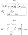
- Fig. 7 shows the configuration of a PLL (Phase-Locked Loop) modulator as another modulator used in a related art portable radio terminal.
- the related art PLL modulator inputs the output signal of the aforementioned quadrature modulator 604 to a phase comparator 606 as a modulated wave.
- the PLL modulator passes a component of phase difference from a signal of the first VCO (first voltage-controlled oscillator) 601 converted to the same frequency through a low-pass filter 607, and inputs the resulting signal to the frequency control terminal of the first VCO 601.
- the numeral 602 designates a second VCO, 608 a first mixer for frequency-converting the output signal of the first VCO based on the output signal of the second VCO.
- the related art PLL modulator supports a modulation system having a constant envelope waveform, for example GMSK, but cannot perform a modulation system accompanied by an amplitude component as information, for example QPSK or CDMA.
- the PLL modulator is in widespread use in a modulation system having a constant envelope waveform such as GMSK, since the out-band noise of the low-pass filter 607 constituting the PLL is substantially determined by the C/N (carrier to noise ratio) so that the residual noise in the wideband is small and it is not necessary to insert a filter in a transmitter.
- Configuration of a modulator supporting two modulation systems amodulation system having a constant envelope waveform and a modulation system accompanied by an amplitude component as information may comprise a PLL modulator and a quadrature modulator respectively for these two modulation systems as shown in Fig. 8.
- the PLL modulator supports the modulation system having a constant envelope waveform while the quadrature modulator supports the modulation system accompanied by an amplitude component as information.
- Band-pass filters 610, 611 are added to the quadrature modulator 605 in order to reduce noise and a third VCO 603 and a second mixer 609 are added in order to set modulated output (transmission signal TS2) according to the service frequency.
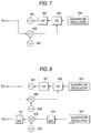
- a configuration is possible where a single quadrature modulator 704 is shared by a modulation system having a constant envelope waveform and a modulation system accompanied by an amplitude component as information in order to generate transmission waves (transmission signals TS1, TS2) via the two modulation systems as shown in Fig. 9.
- This configuration is based on the fact that the quadrature modulator supports both a modulation system having a constant envelope waveform and a modulation system accompanied by an amplitude component as information.
- the two modulation systems have been implemented using dedicated modulators or sharing a quadrature modulator in order to configure a dual-mode portable radio terminal
- the invention has been proposed in view of the conventional art circumstances and aims at providing radio communications apparatus that supports two modulation systems, a modulation system having a constant envelope waveform and a modulation system accompanied by an amplitude component as information, characterized in that the circuit scale of a modulator is reduced to assure compact apparatus design and cost reduction.
- radio communications apparatus comprises a quadrature modulator for composing the transition of the phase of a modulated wave via a in-phase component and a quadrature component, a first voltage-controlled oscillator for outputting a first transmission signal, a first mixer for frequency-converting the first transmission signal based on the output signal of a second voltage-controlled oscillator, a phase comparator for comparing the phase of the output signal of the quadrature modulator with the phase of the output signal of the first mixer, a low-pass filter for filtering the component below a predetermined frequency of the output signal of the phase comparator and supplying the resulting signal to the frequency control terminal of the first voltage-controlled oscillator, and a first band-pass filter for outputting a signal obtained by filtering the component in a predetermined frequency band of the output signal of the quadrature modulator as a second transmission signal.
- Radio communications apparatus is radio communications apparatus according to the first aspect of the invention, characterized in that the apparatus comprises a second mixer for frequency-converting the output signal of the first band-pass filter based on the output signal of a third voltage-controlled oscillator and a second band-pass filter for outputting a signal obtained by filtering the component in a predetermined frequency band of the output signal of the second mixer as a second transmission signal.
- Radio communications apparatus is radio communications apparatus according to the second aspect of the invention, characterized in that the second mixer frequency-converts the output signal of the first band-pass filter based on the output signal of the second voltage-controlled oscillator.
- Radio communications apparatus is radio communications apparatus according to the first, second or third aspect of the invention, characterized in that the apparatus comprises a first transmitter for amplifying a first transmission signal output by the first voltage-controlled oscillator and transmitting the resulting signal via an antenna and a second transmitter for amplifying a second transmission signal output by the first band-pass filter or the secondband-pass filter and transmitting the resulting signal via an antenna.
- the modulator circuit for comparing, via a phase comparator, the phase of the output signal of a quadrature modulator with the phase of the signal obtained by frequency-converting the output signal of a first voltage-controlled oscillator via a second voltage-controlled oscillator and a first mixer, the modulator circuit using a PLLmodulator for filtering, via a low-pass filter, the component below a predetermined frequency of the output signal of the phase comparator and supplying the resulting signal to the frequency control terminal of the first voltage-controlled oscillator, the output signal of the first voltage-controlled oscillator is a modulated signal (first transmission signal) conforming to a modulation system having a constant envelope waveform, for example GMSK, while the output signal of a quadrature modulator is input to the first band-pass filter and the output signal of the first band-pass filter is a modulated signal (second transmission signal) conforming to a modulation system accompanied by an amplitude component as information, for example
- the output signal of the first voltage-controlled oscillator is a modulated signal (first transmission signal) conforming to a modulation system having a constant envelope waveform, for example GMSK, while the signal obtained by frequency-converting the output signal of the first band-pass filter via the second mixer based on the output signal of the third voltage-controlled oscillator, and filtering the component in a predetermined frequency band of the output signal of the second mixer via the second band-pass filter is a modulated signal (second transmission signal) conforming to a modulation system accompanied by an amplitude component as information, for example QPSK or CDMA.
- the output signal of the first voltage-controlled oscillator is a modulated signal (first transmission signal) conforming to a modulation system having a constant envelope waveform, for example GMSK
- the output signal of the second band-pass filter is a modulated signal (second transmission signal) conforming to a modulation system accompanied by an amplitude component as information, for example QPSK or CDMA.
- the second voltage-controlled oscillator and the third voltage-controlled oscillator used for frequency conversion are integrated into a single voltage-controlled oscillator for shared use by adjusting the frequency configuration of transmitter systems so that the second voltage-controlled oscillator andthe third voltage-controlled oscillator may be covered by the oscillation frequency range of a single voltage-controlled oscillator.
- this configuration it is possible to reduce the circuit scale of a modulator to attain compact apparatus design via reduction of the number of apparatus parts and reduction of apparatus cost via cutback of material cost.
- the output signal of a modulator circuit using a PLL modulator is amplified by a first transmitter and transmitted via an antenna
- the output signal of a modulator circuit using a quadrature modulator is amplified by a second transmitter and transmitted via the antenna.
- Fig. 1 shows the configuration of a dual mode modulator 100a of radio communications apparatus according to the first embodiment of the invention.
- the radio communications apparatus of the embodiment comprises a quadrature modulator and a PLL modulator that have been integrated.
- the dual-mode modulator 100 of the embodiment comprises a quadrature modulator 104 for composing the transition of the phase of a modulated wave via a in-phase component and a quadrature component, a first voltage-controlled oscillator (first VCO) 101 for outputting a first transmission signal TS1, a second voltage-controlled oscillator (second VCO) 102, a first mixer 108 for frequency-converting the first transmission signal TS1 based on the output signal of the second VCO 102, a phase comparator (PD) for comparing the phase of the output signal of the quadrature modulator with the phase of the output signal of the first mixer 108, a low-pass filter (LPF) 107 for filtering the component below a predetermined frequency of the output signal of the phase comparator 106 and supplying the resulting signal to the frequency control terminal of the first VCO 101, and a first band-pass filter (BPF) for outputting a signal obtained by filtering the component in a predetermined frequency band of the output
- first VCO voltage
- the output of the quadrature modulator 104 is input to the phase comparator 106.
- a signal obtained by passing the output of the phase comparator 106 through the low-pass filter 107 is input to the first VCO 101.
- the output signal of the first VCO is branched to the first transmission signal TS1 and the input signal of the first mixer 108.
- a signal obtained by frequency conversion via the first mixer 108 and the second VCO 102 is input to the phase comparator 106 together with the output signal of the quadrature modulator 104.
- a modulated signal having a constant envelope waveform for example a GMSK modulated wave is generated as the first transmission signal TS1.
- the output of the quadrature modulator 104 undergoes filtering of the component in a predetermined frequency band via the band-pass filter 110 and is output as the second transmission signal TS2.
- a modulated signal confirming to a modulation system modulation system accompanied by an amplitude component as information, for example QPSK or CDMA is generated, as well as a modulated wave conforming to a modulation system having a constant envelope waveform.
- the phase comparator 106 is comprised in a PLL can be easily integrated.
- the related art configuration shares a quadrature modulator 704 and at the same time a band-pass filters 717 and 718 must be inserted in the transmitter.
- radio communications apparatus of the embodiment it is possible to attain compact apparatus design via reduction of the number of larger parts and cutback of material cost.
- the radio communications apparatus in the embodiment includes a modulator circuit employing th PLL modulator wherein the phase comparator 106 compares the phase of the output signal of the quadrature modulator 104 with the phase of the signal obtained by frequency-converting the output signal of the first VCO 101 via the second VCO 102 and the first mixer 108, and wherein the low-pass filter 107 filters the component below a predetermined frequency of the output signal of the phase comparator 106 and supplies the resulting signal to the frequency control terminal of the first VCO 101.
- the output signal (transmission signal TS1) of the first VCO 101 is a modulated signal conforming to a modulation system having a constant envelope waveform, for example GMSK, while the output signal of the quadrature modulator 104 is input to the first band-pass filter 110 and the output signal (transmission signal TS2) of the first band-pass filter is a modulated signal conforming to a modulation system accompanied by an amplitude component as information, for example QPSK or CDMA.
- Radio communications apparatus comprises, same as the radio communications apparatus according to the first embodiment, a quadrature modulator and a PLL modulator that have been integrated with a mixer and a band-pass filter added to the modulator circuit of a quadrature modulation system.
- the dual-mode modulator 100b of the embodiment same as the dual-mode modulator 100a of the first embodiment, comprises a quadrature modulator 104, a first voltage-controlled oscillator (first VCO) 101, a second voltage-controlled oscillator (second VCO) 102, a first mixer 108, a phase comparator (PD) 106, a low-pass filter (LPF) 107 and a first band-pass filter (BPF) 110.
- first VCO voltage-controlled oscillator
- second VCO second voltage-controlled oscillator
- PD phase comparator
- LPF low-pass filter
- BPF band-pass filter
- the dual-mode modulator 100b further comprises a third voltage-controlled oscillator (third VCO) 103, a second mixer 109 for frequency-converting the output signal of the first band-pass filter 110 based on the output signal of the third VCO 103 and a second band-pass filter (BPF) 111 for outputting a signal obtained by filtering the component in a predetermined frequency band of the output signal of the second mixer 109.
- third VCO voltage-controlled oscillator
- BPF second band-pass filter
- the output signal (transmission signal TS1) of the first VCO 101 is a modulated signal conforming to a modulation system having a constant envelope waveform, for example GMSK, while the signal obtained by frequency-converting the output signal of the first band-pass filter 110 via the second mixer based on the output signal of the third VCO 103, and filtering the component in a predetermined frequency band of the output signal of the second mixer 109 via the second band-pass filter 111 is a modulated signal conforming to a modulation system accompanied by an amplitude component as information, for example QPSK or CDMA.
- a modulation system having a constant envelope wave form and a modulation system accompanied by an amplitude component as information it is possible to reduce the circuit scale of a modulator to attain compact apparatus design and cost reduction, as well as set the second transmission signal TS2 according to the service frequency.
- Fig. 3 shows the configuration of radio communications apparatus according to the third embodiment of the invention.
- Radio communications apparatus according to the embodiment configures the transmission system of the radio communications apparatus by using the dual-mode modulator 100b according to the second embodiment.
- radio communications apparatus of the embodiment comprises a dual-mode modulator 100b according to the second embodiment, a first antenna 203, a first power amplifier (first transmitter) 202 for amplifying the first transmission signal TS1 output by the first VCO 101 and transmitting the resulting signal via the first antenna 203, a second antenna 205, and a second power amplifier (second transmitter) 204 for amplifying the second transmission signal TS2 output by the second band-pass filter 111 and transmitting the resulting signal via the second antenna 205.
- first transmitter first transmitter
- second transmitter second transmitter
- radio communications apparatus of the embodiment it is possible to configure dual-mode radio communications apparatus comprising a first system where the first transmission signal TS1 is amplified by the first power amplifier 202 and transmitted from the first antenna 203 and a second system where the second transmission signal TS2 is amplified by the second power amplifier 204 and transmitted from the second antenna 205. Further, by switching between the oscillating frequencies of the first VCO 101, second VCO 102 and third VCO 103, it is possible to configure compact radio communications apparatus supporting a plurality of frequency bands and a plurality of modes.
- Radio communications apparatus comprises, same as the radio communications apparatus according to the first and second embodiments, a quadrature modulator and a PLL modulator that have been integrated and the second VCO 102 and the third VCO 103 in the radio communications apparatus according to the second embodiment that have been integrated into a single VCO.
- the dual-mode modulator 100c of the embodiment same as the dual-mode modulator 100a of the first embodiment, comprises a quadrature modulator 104, a first voltage-controlled oscillator (first VCO) 101, a second voltage-controlled oscillator (second VCO) 102', a first mixer 108, a phase comparator (PD) 106, a low-pass filter (LPF) 107 and a first band-pass filter (BPF) 110.
- first VCO voltage-controlled oscillator
- second VCO second voltage-controlled oscillator
- PD phase comparator
- LPF low-pass filter
- BPF band-pass filter
- the dual-mode modulator 100c also comprises a second mixer 109 for frequency-converting the output signal of the first band-pass filter 110 based on the output signal of the second VCO 102' and a second band-pass filter (BPF) 111 for outputting a signal obtained by filtering the component in a predetermined frequency band of the output signal of the second mixer 109.
- BPF band-pass filter
- radio communications apparatus of the embodiment by adjusting the frequency configuration in each transmitter system so that the oscillating frequencies of the second VCO 102 and the third VCO 103 in radio communications apparatus according to the second embodiment may be covered by the oscillation frequency range of a single VCO 102', the second VCO 102 and the third VCO 103 used for frequency conversion are integrated for shared use. Via this configuration, it is possible to reduce the number of VCOs and further attaining compact design of a modulator circuit.
- Fig. 5 shows the configuration of radio communications apparatus according to the fifth embodiment of the invention.
- Radio communications apparatus according to the embodiment configures the transmission system of the radio communications apparatus by using the dual-mode modulator 100c according to the fourth embodiment.
- radio communications apparatus of the embodiment comprises a dual-mode modulator 100c according to the fourth embodiment, a first antenna 203, a first power amplifier (first transmitter) 202 for amplifying the first transmission signal TS1 output by the first VCO 101 and transmitting the resulting signal via the first antenna 203, a second antenna 205, and a second power amplifier (second transmitter) 204 for amplifying the second transmission signal TS2 output by the second band-pass filter 111 and transmitting the resulting signal via the second antenna 205.
- first transmitter first transmitter
- second transmitter second transmitter
- radio communications apparatus of the embodiment it is possible to configure dual-mode radio communications apparatus comprising a first system where the first transmission signal TS1 is amplified by the first power amplifier 202 and transmitted from the first antenna 203 and a second system where the second transmission signal TS2 is amplified by the second power amplifier 204 and transmitted from the second antenna 205. Further, by switching between the oscillating frequencies of the first VCO 101, second VCO 102 and third VCO 103, it is possible to configure compact radio communications apparatus supporting a plurality of frequency bands and a plurality of modes.
- the radio communications apparatus in the embodiment includes a modulator circuit employing th PLL modulator wherein the phase comparator 106 compares the phase of the output signal of the quadrature modulator 104 with the phase of the signal obtained by frequency-converting the output signal of the first VCO 101 via the second VCO 102 and the first mixer 108, and wherein the low-pass filter 107 filters the component below a predetermined frequency of the output signal of the phase comparator 106 and supplies the resulting signal to the frequency control terminal of the first VCO 101.
- the output signal of the first voltage-controlled oscillator is a modulated signal (first transmission signal) conforming to a modulation system having a constant envelope waveform
- the output signal of a quadrature modulator is input to the first band-pass filter and the output signal of the first band-pass filter is a modulated signal (second transmission signal) conforming to a modulation system accompanied by an amplitude component as information.
- the output signal of the first voltage-controlled oscillator is a modulated signal (first transmission signal) conforming to a modulation system having a constant envelope waveform
- the signal obtained by frequency-converting the output signal of the first band-pass filter via the second mixer based on the output signal of the third voltage-controlled oscillator, and filtering the component in a predetermined frequency band of the output signal of the second mixer via the second band-pass filter is a modulated signal (second transmission signal) conforming to a modulation system accompanied by an amplitude component as information.
- a modulation system having a constant envelope waveform and a modulation system accompanied by an amplitude component as information it is possible to reduce the circuit scale of a modulator to attain compact apparatus design and cost reduction, as well as set the second transmission signal according to the service frequency.
- radio communications apparatus of the invention by adjusting the frequency configuration of transmitter systems so that the second voltage-controlled oscillator and the third voltage-controlled oscillator may be covered by the oscillation frequency range of a single voltage-controlled oscillator and integrating the second voltage-controlled oscillator and the third voltage-controlled oscillator used for frequency conversion into a single voltage-controlled oscillator for shared use, it is possible to reduce the circuit scale of a modulator to attain compact apparatus design via reduction of the number of apparatus parts and reduction of apparatus cost via cutback of material cost.
- the output signal of a modulator circuit using a PLL modulator is amplified by a first transmitter and transmitted via an antenna
- the output signal of a modulator circuit using a quadrature modulator is amplified by a second transmitter and transmitted via the antenna.
Landscapes
- Engineering & Computer Science (AREA)
- Computer Networks & Wireless Communication (AREA)
- Signal Processing (AREA)
- Power Engineering (AREA)
- Transmitters (AREA)
- Digital Transmission Methods That Use Modulated Carrier Waves (AREA)
Applications Claiming Priority (2)
| Application Number | Priority Date | Filing Date | Title |
|---|---|---|---|
| JP2000199233 | 2000-06-30 | ||
| JP2000199233A JP2002016654A (ja) | 2000-06-30 | 2000-06-30 | 無線通信装置 |
Publications (2)
| Publication Number | Publication Date |
|---|---|
| EP1168648A2 true EP1168648A2 (fr) | 2002-01-02 |
| EP1168648A3 EP1168648A3 (fr) | 2004-12-15 |
Family
ID=18697284
Family Applications (1)
| Application Number | Title | Priority Date | Filing Date |
|---|---|---|---|
| EP01115475A Withdrawn EP1168648A3 (fr) | 2000-06-30 | 2001-06-27 | Appareil de communication radio |
Country Status (4)
| Country | Link |
|---|---|
| US (1) | US6973136B2 (fr) |
| EP (1) | EP1168648A3 (fr) |
| JP (1) | JP2002016654A (fr) |
| CN (1) | CN1330457A (fr) |
Families Citing this family (9)
| Publication number | Priority date | Publication date | Assignee | Title |
|---|---|---|---|---|
| WO2004002098A1 (fr) * | 2002-06-19 | 2003-12-31 | Hitachi, Ltd. | Appareil de radiocommunication |
| DE602004008592T2 (de) * | 2004-06-04 | 2007-12-27 | Honda Research Institute Europe Gmbh | Bestimmung einer gemeinsamen Quelle zweier harmonischer Komponenten |
| JP4372713B2 (ja) * | 2005-03-31 | 2009-11-25 | 株式会社日立国際電気 | 位相制御方法及び合成受信機 |
| US7822392B2 (en) * | 2006-11-13 | 2010-10-26 | Panasonic Corporation | Frequency modulation circuit, transmission circuit and communication device |
| KR101481507B1 (ko) * | 2007-03-12 | 2015-01-13 | 엘지전자 주식회사 | 부가 제어 신호 송수신 방법 |
| US20090215387A1 (en) * | 2008-01-16 | 2009-08-27 | Brennan Joseph P | In-vehicle cellular device blocker to restrict cellular use for operator |
| US20110065456A1 (en) * | 2009-04-20 | 2011-03-17 | Brennan Joseph P | Cellular device deactivation system |
| KR20120020164A (ko) * | 2009-05-08 | 2012-03-07 | 오브에지, 엘엘씨 | 차량 작동자에 의한 모바일 장치의 사용에 대한 정책 기반 제어 및 모니터링을 위한 시스템, 방법, 및 장치 |
| JP5075189B2 (ja) * | 2009-12-03 | 2012-11-14 | 株式会社エヌ・ティ・ティ・ドコモ | 無線通信端末 |
Family Cites Families (3)
| Publication number | Priority date | Publication date | Assignee | Title |
|---|---|---|---|---|
| US6185259B1 (en) * | 1996-06-12 | 2001-02-06 | Ericsson Inc. | Transmitter/receiver for GMSK and offset-QAM |
| JP3898830B2 (ja) * | 1998-03-04 | 2007-03-28 | 株式会社日立製作所 | マルチバンド無線端末装置 |
| US6208875B1 (en) * | 1998-04-08 | 2001-03-27 | Conexant Systems, Inc. | RF architecture for cellular dual-band telephones |
-
2000
- 2000-06-30 JP JP2000199233A patent/JP2002016654A/ja active Pending
-
2001
- 2001-06-27 EP EP01115475A patent/EP1168648A3/fr not_active Withdrawn
- 2001-06-28 US US09/893,854 patent/US6973136B2/en not_active Expired - Fee Related
- 2001-06-29 CN CN01117558.3A patent/CN1330457A/zh active Pending
Also Published As
| Publication number | Publication date |
|---|---|
| CN1330457A (zh) | 2002-01-09 |
| EP1168648A3 (fr) | 2004-12-15 |
| US6973136B2 (en) | 2005-12-06 |
| JP2002016654A (ja) | 2002-01-18 |
| US20020000890A1 (en) | 2002-01-03 |
Similar Documents
| Publication | Publication Date | Title |
|---|---|---|
| US7058380B2 (en) | Multiband radio signal transmitter/receiver | |
| US6766178B1 (en) | RF architecture for cellular multi-band telephones | |
| US5822366A (en) | Transceiver and method for generating and processing complex I/Q-signals | |
| USRE41583E1 (en) | Frequency-stabilized transceiver configuration | |
| EP0619656B1 (fr) | Système de transmission réception à multiplexage temporel | |
| US20080182617A1 (en) | Multiband mobile communication apparatus | |
| US7239855B2 (en) | communication semiconductor integrated circuit device and wireless communication system | |
| US6747987B1 (en) | Transmit modulation circuit and method of operating a transmitter | |
| US6973136B2 (en) | Radio communications apparatus | |
| US6369666B1 (en) | Modulator circuit configuration | |
| EP1434362B1 (fr) | Système de saut de fréquence et méthode correspondante | |
| WO2004040872A1 (fr) | Emetteur de telecommunication utilisant une boucle a phase asservie decalee | |
| CN1218496C (zh) | 新型低成本/低功率模拟收发机结构 | |
| US6912376B1 (en) | Mobile phone transceiver | |
| JPH1093475A (ja) | 複合システム共用端末 | |
| US7398074B2 (en) | Integrated transceiver circuit with low interference production and sensitivity | |
| US6952593B2 (en) | Multi-band tranceivers with reduced frequency sources for digital transmissions | |
| US7333554B2 (en) | Communication system with frequency modulation and a single local oscillator | |
| WO2004002098A1 (fr) | Appareil de radiocommunication | |
| JP3825317B2 (ja) | フェーズロックループおよび直交位相変調器の両方を用いたfm変調器 | |
| GB2325362A (en) | Transceiver which uses transmission signal as local oscillator for reception | |
| US8412116B1 (en) | Wireless transceiver | |
| JP2003018231A (ja) | デジタル変調送信機 | |
| US6137997A (en) | Circuit for receiving and transmitting signals and method | |
| JP2000040969A (ja) | マルチバンド無線装置 |
Legal Events
| Date | Code | Title | Description |
|---|---|---|---|
| PUAI | Public reference made under article 153(3) epc to a published international application that has entered the european phase |
Free format text: ORIGINAL CODE: 0009012 |
|
| AK | Designated contracting states |
Kind code of ref document: A2 Designated state(s): AT BE CH CY DE DK ES FI FR GB GR IE IT LI LU MC NL PT SE TR |
|
| AX | Request for extension of the european patent |
Free format text: AL;LT;LV;MK;RO;SI |
|
| PUAL | Search report despatched |
Free format text: ORIGINAL CODE: 0009013 |
|
| AK | Designated contracting states |
Kind code of ref document: A3 Designated state(s): AT BE CH CY DE DK ES FI FR GB GR IE IT LI LU MC NL PT SE TR |
|
| AX | Request for extension of the european patent |
Extension state: AL LT LV MK RO SI |
|
| 17P | Request for examination filed |
Effective date: 20050303 |
|
| 17Q | First examination report despatched |
Effective date: 20050420 |
|
| AKX | Designation fees paid |
Designated state(s): AT BE CH CY DE DK ES FI FR GB GR IE IT LI LU MC NL PT SE TR |
|
| GRAP | Despatch of communication of intention to grant a patent |
Free format text: ORIGINAL CODE: EPIDOSNIGR1 |
|
| STAA | Information on the status of an ep patent application or granted ep patent |
Free format text: STATUS: THE APPLICATION IS DEEMED TO BE WITHDRAWN |
|
| 18D | Application deemed to be withdrawn |
Effective date: 20060811 |