EP1169950A2 - Schulterabsenkung für Federholzleisten am Grundrahmen eines Lattenrostes - Google Patents
Schulterabsenkung für Federholzleisten am Grundrahmen eines Lattenrostes Download PDFInfo
- Publication number
- EP1169950A2 EP1169950A2 EP01115990A EP01115990A EP1169950A2 EP 1169950 A2 EP1169950 A2 EP 1169950A2 EP 01115990 A EP01115990 A EP 01115990A EP 01115990 A EP01115990 A EP 01115990A EP 1169950 A2 EP1169950 A2 EP 1169950A2
- Authority
- EP
- European Patent Office
- Prior art keywords
- section
- vertical section
- spring
- wooden slats
- shoulder
- Prior art date
- Legal status (The legal status is an assumption and is not a legal conclusion. Google has not performed a legal analysis and makes no representation as to the accuracy of the status listed.)
- Granted
Links
Images


Classifications
-
- A—HUMAN NECESSITIES
- A47—FURNITURE; DOMESTIC ARTICLES OR APPLIANCES; COFFEE MILLS; SPICE MILLS; SUCTION CLEANERS IN GENERAL
- A47C—CHAIRS; SOFAS; BEDS
- A47C23/00—Spring mattresses with rigid frame or forming part of the bedstead, e.g. box springs; Divan bases; Slatted bed bases
- A47C23/06—Spring mattresses with rigid frame or forming part of the bedstead, e.g. box springs; Divan bases; Slatted bed bases using wooden springs, e.g. of slat type
- A47C23/062—Slat supports
- A47C23/063—Slat supports by elastic means, e.g. coil springs
- A47C23/064—Slat supports by elastic means, e.g. coil springs by elastomeric springs
Definitions
- the invention relates to a shoulder lowering for wooden slats on the base frame of a slatted frame, consisting of a resilient Base body, which as a one-piece, manufactured by injection molding Plastic part is designed and a large area vertical section which, in the installed position on the longitudinal spar of the Base frame bears and stored in this longitudinal spar with dowel pins is, wherein the base body further comprises two spring arms each of which has a cylindrical section for receiving the spring wooden slats wearing caps is designed.
- Slatted frames for seating and reclining furniture are available in numerous designs known. Regardless of the specific construction the basic structure of the slatted frames is similar, they exist predominantly from a base frame with associated slats.
- the connection between the base frame and the slats is preferably carried out with elastic bearing elements, the Base frame are supported and the front of the spring wooden slats reach around like a cap.
- Such a connection is according to EP 254 702 B 1 designed as a metal leaf spring on the base frame is supported and a contour course effective as a spring clip has, at its upper portion two cap-shaped receiving elements for the slats are attached. With this construction pleasant suspension behavior is achieved.
- EP 254 702 B1 is not suitable for flat slatted frames made by increasingly demanded by industry and end users become.
- Another disadvantage is the largely rigid arrangement the cap-shaped receiving elements on the metal bracket.
- Slatted frames with different distances between each Spring wood slats also require separate bearing elements.
- a reduced height and an improved adaptation to different Strip spacing can be characterized by elastic bearing elements Plastic can be achieved.
- Such bearing elements are, for example according to DE 197 14 706 A 1 or DE 297 04 454 U 1 with demanding geometric contours or from specially coordinated material combinations made to provide good suspension comfort to reach.
- Only relatively small spring travel can be realized.
- a typical section for the need for larger spring travel is the range of Shoulder pad.
- special ones have been created Developed assemblies called "shoulder lowering" and e.g. known from DE 298 03 413 U 1 and from DE 298 22 020 U 1 are.
- the shoulder lowering is on the base frame of the slatted frame supported and with an elastic bearing element made of plastic completed, in which the spring wooden slats are supported become.
- Such shoulder drops have become more functional Basically proven view.
- the disadvantage, however, is that the possible travel is still too short to be used in all stresses to achieve a noticeable improvement in comfort.
- the shoulder depressions known to date consist of numerous Individual parts and therefore cause considerable manufacturing and expense.
- comfort storage is a technical Solution available that has a low vertical height and yet manufactured and assembled with little effort can be.
- This is achieved by the comfort storage from one resilient base body, which is in one piece, in the injection molding process manufactured plastic part is designed.
- the Base body has a large vertical section, which lies in the installed position on the longitudinal spar of the base frame and with dowel pins is stored in this longitudinal spar.
- the main body has also two spring arms, each with a cylindrical section designed to accommodate the caps bearing the spring wooden slats is. Power transmission from the caps to the subordinate ones Sections of the base body require a compact design in the transition area between spring arm and cylindrical Section.
- the object of the invention is to provide a shoulder lowering which consists of only one component, a longer travel guaranteed and at the same time a reduced distance between allows the slats. This is said to be achieved in particular be by the spring movement in a different from that to Longitudinal spar of the base frame parallel plane is realized.
- the spring arms largely arranged at right angles to the large vertical section are and each have a contour that of the vertical section proceeding approximately parallel in a lower section runs to the slats, then into an arch Section merges, subsequently in an upper section again almost parallel to the slats, but at a distance runs to the lower section, then into a vertical one Section merges with a short distance and approximately is arranged parallel to the large vertical section and finally in the cylindrical section for receiving the spring slats wearing caps.
- the proposed shoulder lowering is advantageous from just one component and therefore requires little effort for manufacture and assembly.
- By realizing the spring movement in a different plane than the plane parallel to the A longer suspension travel is possible along the longitudinal spar of the base frame.
- the overall length of the base body can be in the direction of the longitudinal spar can be significantly reduced, so that smaller distances between the slats are also possible.
- This construction is basically for every section of the base frame suitable, but their preferred application is in the field the shoulder zone.
- the shoulder depression shown in the drawing is for the Support of spring wooden slats on the base frame of a slatted frame used. This technical solution is preferably in the field of Shoulder pad mounted.
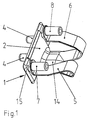
- the shoulder lowering consists of one resilient base body 1.
- the base body 1 is in one piece Plastic part designed and is manufactured by injection molding.
- the base body 1 has a large-area section 2 on. In the installed position, this section 2 runs vertically and lies on the longitudinal spar 3 of the base frame.
- Two spring arms 5 and 6 are also provided on the base body 1.
- the cylindrical sections 7; 8 become caps 9 assigned to which the - not shown in the drawing - Spring slats are stored.
- the concrete design the cylindrical sections 7 and 8 is in the present situation relatively insignificant. However, a design is expedient, which alternatively allows caps 9 of different shapes to be accommodated.
- the two spring arms 5 and 6 are largely perpendicular to the large area vertical section 2 arranged.
- Each spring arm 5 or 6 has a contour that extends from the vertical section 2 of the base body 1, initially designed as a lower section 10 is.
- This lower section 10 runs approximately parallel to the (not shown) spring slats and goes into an arc Section 11 about.
- the arcuate section 11 into an upper section 12.
- This section 12 runs approximately like the lower section 10 parallel to the slats, between these two sections 10 and 12 a vertical distance remains.
- the top section 12 merges into a section 13.
- This section 13 runs largely perpendicular, so it is almost parallel to large and vertical section 2 of the base body 1 is arranged.
- Section 13 finally goes into the further course of the contour cylindrical section 7 or 8 for receiving the spring wooden slats wearing caps 9 over.
- the spring arms 5 and 6 can directly from the large vertical Branch section 2 of the main body 1. With such a construction is the achievable stability of the entire shoulder depression limited. There are advantages if the large area vertical section 2 in its lower area first in passes over another large-area section 14. A corresponding Design is also shown in the drawing.
- the section 14 is arranged at right angles to the vertical section 2, in the installed position, it runs horizontally. This is where the spring arms begin 5 and 6 on the horizontal section 14 of the base body 1 and go directly into their respective lower section 10. In this compact construction, the spring arms 5 and 6 run advantageously starting from the lower, large-area section 14 above and outside.
- the spring movement move the upper section 12 laterally past the lower section 10, so that the possible travel is larger than the distance between these two sections 10 and 12 in the rest position.
- the large-area horizontal section 14 at its Top has a spherical contour. With strong compression the connecting web of the caps 9 lies flat on this contour of section 14, which consequently limits the maximum Travel causes. Excessive stress on the body 1, which could cause permanent deformation, is therefore locked out.
- the basic body 1 has additional step-shaped paragraphs 15.
- Paragraphs 15 are on the large vertical section 2 on the two side areas provided that the respective vertical section 13 the spring arms 5 and 6 is assigned. These sections are therefore located 13 on compression at paragraphs 15 and cannot move sideways dodge. This will ensure the overall stability of the shoulder drop additionally increased.
Landscapes
- Mattresses And Other Support Structures For Chairs And Beds (AREA)
- Table Equipment (AREA)
- Chemical And Physical Treatments For Wood And The Like (AREA)
- Finished Plywoods (AREA)
- Chain Conveyers (AREA)
- Injection Moulding Of Plastics Or The Like (AREA)
- Springs (AREA)
Abstract
Description
- Fig. 1
- eine Schulterabsenkung in perspektivischer Ansicht
- Fig. 2
- die Schulterabsenkung gemäß Fig. 1 in Seitenansicht
- Fig. 3
- die Schulterabsenkung gemäß Fig. 1 in Draufsicht
- Fig. 4
- eine Schulterabsenkung mit zugeordneten Bauteilen als Einzelteile
- Fig. 5
- die Schulterabsenkung gemäß Fig. 4 nach erfolgter Montage
- 1
- Grundkörper
- 2
- großflächiger senkrechter Abschnitt am Grundkörper
- 3
- Längsholm des Grundrahmens
- 4
- Dübelzapfen
- 5
- erster Federarm
- 6
- zweiter Federarm
- 7
- zylindrischer Abschnitt am ersten Federarm
- 8
- zylindrischer Abschnitt am zweiten Federarm
- 9
- Aufnahmekappen für Federholzleisten
- 10
- unterer Abschnitt der Federarme
- 11
- bogenförmiger Abschnitt der Federarme
- 12
- oberer Abschnitt der Federarme
- 13
- senkrechter Abschnitt der Federarme
- 14
- großflächiger waagerechter Abschnitt am Grundkörper
- 15
- stufenförmige Absätze am Grundkörper
- 16
- ballige Außenkontur der zylindrischen Abschnitte
Claims (6)
- Schulterabsenkung für Federholzleisten am Grundrahmen eines Lattenrostes, bestehend aus einem federnden Grundkörper, der als einstückiges, im Spritzgießverfahren hergestelltes Kunststoffteil ausgestaltet ist und einen großflächigen senkrechten Abschnitt aufweist, der in Einbaulage am Längsholm des Grundrahmens anliegt und mit Dübelzapfen in diesem Längsholm gelagert ist, wobei der Grundkörper ferner zwei Federarme aufweist, an denen jeweils ein zylindrischer Abschnitt zur Aufnahme der die Federholzleisten tragenden Kappen ausgestaltet ist,
dadurch gekennzeichnet, dass die Federarme (5; 6) weitgehend rechtwinklig zum großflächigen senkrechten Abschnitt (2) angeordnet sind und jeweils eine Kontur aufweisen, die vom senkrechten Abschnitt (2) ausgehend zunächst in einem unteren Abschnitt (10) annähernd parallel zu den Federholzleisten verläuft, danach in einen bogenförmigen Abschnitt (11) übergeht, nachfolgend in einem oberen Abschnitt (12) wieder annähernd parallel zu den Federholzleisten, jedoch mit Abstand zum unteren Abschnitt (10) verläuft, anschließend in einen senkrechten Abschnitt (13) übergeht, der mit geringem Abstand und annähernd parallel zum großflächigen senkrechten Abschnitt (2) angeordnet ist und schließlich in den zylindrischen Abschnitt (7; 8) zur Aufnahme der die Federholzleisten tragenden Kappen (9) übergeht. - Schulterabsenkung nach Anspruch 1,
dadurch gekennzeichnet, dass der großflächige senkrechte Abschnitt (2) in seinem unteren Bereich in einen weiteren großflächigen Abschnitt (14) übergeht, der rechtwinklig zu diesem senkrechten Abschnitt (2) angeordnet ist und vom dem die Federarme (5; 6) unmittelbar in ihren jeweiligen unteren Abschnitt (10) übergehen. - Schulterabsenkung nach den Ansprüchen 1 und 2,
dadurch gekennzeichnet, dass die Federarme (5; 6) vom großflächigen waagerechten Abschnitt (14) ausgehend nach oben außen verlaufend angeordnet sind. - Schulterabsenkung nach den Ansprüchen 1 und 2,
dadurch gekennzeichnet, dass der großflächige waagerechte Abschnitt (14) an seiner Oberseite eine ballige Kontur aufweist. - Schulterabsenkung nach Anspruch 1,
dadurch gekennzeichnet, dass der großflächige senkrechte Abschnitt (2) an den Seitenbereichen, denen der senkrechte Abschnitt (13) der Federarme (5; 6) zugeordnet ist, jeweils einen stufenförmigen Absatz (15) aufweist. - Schulterabsenkung nach Anspruch 1,
dadurch gekennzeichnet, dass die zylindrischen Abschnitte (7; 8) zur Aufnahme der die Federholzleisten tragenden Kappen (9) an ihrer, dem großflächigen senkrechten Abschnitt (2) zugeordneten Stirnseite jeweils eine ballige Außenkontur (16) aufweisen.
Applications Claiming Priority (2)
| Application Number | Priority Date | Filing Date | Title |
|---|---|---|---|
| DE10033003A DE10033003C1 (de) | 2000-07-06 | 2000-07-06 | Schulterabsenkung für Federholzleisten am Grundrahmen eines Lattenrostes |
| DE10033003 | 2000-07-06 |
Publications (3)
| Publication Number | Publication Date |
|---|---|
| EP1169950A2 true EP1169950A2 (de) | 2002-01-09 |
| EP1169950A3 EP1169950A3 (de) | 2004-01-14 |
| EP1169950B1 EP1169950B1 (de) | 2006-05-24 |
Family
ID=7648097
Family Applications (1)
| Application Number | Title | Priority Date | Filing Date |
|---|---|---|---|
| EP01115990A Expired - Lifetime EP1169950B1 (de) | 2000-07-06 | 2001-06-30 | Schulterabsenkung für Federholzleisten am Grundrahmen eines Lattenrostes |
Country Status (3)
| Country | Link |
|---|---|
| EP (1) | EP1169950B1 (de) |
| AT (1) | ATE326882T1 (de) |
| DE (2) | DE10033003C1 (de) |
Families Citing this family (4)
| Publication number | Priority date | Publication date | Assignee | Title |
|---|---|---|---|---|
| DE20208434U1 (de) | 2002-05-31 | 2003-07-24 | Recticel Schlafkomfort GmbH, 44867 Bochum | Aufnahme von drei parallel angeordneten Federleisten von Lattenrosten |
| EP1425995B1 (de) | 2002-12-06 | 2006-04-26 | LS Bedding | Vorrichtung zur Befestigung einer Federleiste an den Rahmen eines Lattenrosts |
| GB2492571B (en) * | 2011-07-06 | 2013-09-18 | Proto Magic Innovations Ltd | A mattress variator retention means |
| DE202014100104U1 (de) | 2014-01-10 | 2015-01-12 | Froli Kunststoffwerk Heinrich Fromme, Inh. Margret Fromme-Ruthmann E.Kfr. | Lagervorrichtung für eine Federleiste mit federnder Absenkung an einem Bettenlattenrost |
Citations (6)
| Publication number | Priority date | Publication date | Assignee | Title |
|---|---|---|---|---|
| EP0254702A1 (de) | 1986-07-22 | 1988-01-27 | Acor Products N.V. | Matratzenboden |
| DE29704454U1 (de) | 1997-03-12 | 1997-05-07 | Hartmann, Siegbert, 32584 Löhne | Elastisches Endpunktlager |
| EP0801916A1 (de) | 1996-04-20 | 1997-10-22 | Heinz Grund | Komfort-Lagerung für Federholzleisten am Grundrahmen eines Lattenrostes |
| DE19714706A1 (de) | 1996-04-10 | 1997-10-30 | Froli Kunststoffe Heinrich Fro | Endkappe zur federnden Lagerung von Latten eines Lattenrostes |
| DE29822020U1 (de) | 1998-12-11 | 1999-03-18 | Hartmann, Siegbert, 32584 Löhne | Lagerung für Federleisten von Bettlattenrosten mit Schulterabsenkung |
| DE29803413U1 (de) | 1998-02-27 | 1999-04-22 | OPTIMO Möbelhandelsgesellschaft mbH, 84359 Simbach | Versenkbare Schulterabsenkung |
Family Cites Families (4)
| Publication number | Priority date | Publication date | Assignee | Title |
|---|---|---|---|---|
| DE3510971A1 (de) * | 1985-03-26 | 1986-10-09 | Metzeler Schaum Gmbh, 8940 Memmingen | Elastische halterung fuer die federlatten eines lattenrostes |
| DE59201945D1 (de) * | 1991-05-09 | 1995-05-24 | Roessle & Wanner Gmbh | Lattenrost. |
| DE19538082A1 (de) * | 1995-10-13 | 1997-04-17 | Roessle & Wanner Gmbh | Lattenrost |
| EP1034726A1 (de) * | 1999-03-09 | 2000-09-13 | Recticel Bedding (Schweiz) GmbH | Verfahren zum Verbinden eines Verankerungsteils aus Kunststoff mit einem Bauteil aus Holz, Verankerungsteil, Verbindungsteil sowie Lattenuntermatratze |
-
2000
- 2000-07-06 DE DE10033003A patent/DE10033003C1/de not_active Expired - Fee Related
-
2001
- 2001-06-30 EP EP01115990A patent/EP1169950B1/de not_active Expired - Lifetime
- 2001-06-30 AT AT01115990T patent/ATE326882T1/de not_active IP Right Cessation
- 2001-06-30 DE DE50109851T patent/DE50109851D1/de not_active Expired - Fee Related
Patent Citations (6)
| Publication number | Priority date | Publication date | Assignee | Title |
|---|---|---|---|---|
| EP0254702A1 (de) | 1986-07-22 | 1988-01-27 | Acor Products N.V. | Matratzenboden |
| DE19714706A1 (de) | 1996-04-10 | 1997-10-30 | Froli Kunststoffe Heinrich Fro | Endkappe zur federnden Lagerung von Latten eines Lattenrostes |
| EP0801916A1 (de) | 1996-04-20 | 1997-10-22 | Heinz Grund | Komfort-Lagerung für Federholzleisten am Grundrahmen eines Lattenrostes |
| DE29704454U1 (de) | 1997-03-12 | 1997-05-07 | Hartmann, Siegbert, 32584 Löhne | Elastisches Endpunktlager |
| DE29803413U1 (de) | 1998-02-27 | 1999-04-22 | OPTIMO Möbelhandelsgesellschaft mbH, 84359 Simbach | Versenkbare Schulterabsenkung |
| DE29822020U1 (de) | 1998-12-11 | 1999-03-18 | Hartmann, Siegbert, 32584 Löhne | Lagerung für Federleisten von Bettlattenrosten mit Schulterabsenkung |
Also Published As
| Publication number | Publication date |
|---|---|
| DE50109851D1 (de) | 2006-06-29 |
| EP1169950A3 (de) | 2004-01-14 |
| DE10033003C1 (de) | 2001-10-31 |
| ATE326882T1 (de) | 2006-06-15 |
| EP1169950B1 (de) | 2006-05-24 |
Similar Documents
| Publication | Publication Date | Title |
|---|---|---|
| AT395227B (de) | Skischuh mit einer starren schale | |
| EP0420882A1 (de) | Schiene für schienenfahrzeuge. | |
| DE29517590U1 (de) | Kettenförderer mit verbesserten Gleiteigenschaften | |
| EP3426507A1 (de) | Federeinheit für eine radaufhängung eines fahrzeugs sowie radaufhängung | |
| EP0586781A1 (de) | Spielfigur mit spreizbaren Beinen | |
| DE20202050U1 (de) | Stützkörper, insbesondere zur elastischen Abstützung eines Sitz- oder Liegeelements | |
| EP0512569A1 (de) | Lattenrost | |
| EP1169950B1 (de) | Schulterabsenkung für Federholzleisten am Grundrahmen eines Lattenrostes | |
| EP1311355B1 (de) | Werkzeugspannvorrichtung für ein formwerkzeug, insbesondere einer abkantpresse | |
| DE3144998A1 (de) | Seitenlagerung fuer einen eisenbahnwagen | |
| DE2703511C2 (de) | Lagerkörper für die Lagerung von Federleisten an Seitenteilen eines Bettrahmens | |
| DE3226149C2 (de) | Polsterträger für eine Kopfstütze | |
| EP0191887A2 (de) | Seiten- und Sattelstegpartie für eine Brille | |
| EP0356637B1 (de) | Sportschuh, insbesondere Fussballschuh | |
| DE3337438A1 (de) | Profilleiste | |
| DE69002589T2 (de) | Federungs- und dämpfungseinrichtung für schienenfahrzeuge mit steuerbaren achsen. | |
| EP3991604A1 (de) | Federbauteil für ein sitzmöbel, anordnung für ein sitzmöbel und sitzmöbel | |
| DE19860619A1 (de) | Stützkörper für Federleisten einer Unterfederung von insbesondere Sitz- und Liegemöbeln | |
| DE19615762C1 (de) | Komfort-Lagerung für Federholzleisten am Grundrahmen eines Lattenrostes | |
| EP0716822B1 (de) | Federelement | |
| EP0825823B1 (de) | Lattenrost | |
| DE19711871C2 (de) | Lager für eine in der Radaufhängung eines Kraftfahrzeuges vorgesehene Querblattfeder | |
| DE7736164U1 (de) | 29.11.76 V.St.v.Amerika 745832 27.12.76 V.St.v.Amerika 754280 Einzelradaufhängung für Fahrzeuge | |
| EP0084812B1 (de) | Skiabweiser | |
| DE9413776U1 (de) | Beschlag für einen Lattenrost |
Legal Events
| Date | Code | Title | Description |
|---|---|---|---|
| PUAI | Public reference made under article 153(3) epc to a published international application that has entered the european phase |
Free format text: ORIGINAL CODE: 0009012 |
|
| AK | Designated contracting states |
Kind code of ref document: A2 Designated state(s): AT BE CH CY DE DK ES FI FR GB GR IE IT LI LU MC NL PT SE TR |
|
| AX | Request for extension of the european patent |
Free format text: AL;LT;LV;MK;RO;SI |
|
| PUAL | Search report despatched |
Free format text: ORIGINAL CODE: 0009013 |
|
| AK | Designated contracting states |
Kind code of ref document: A3 Designated state(s): AT BE CH CY DE DK ES FI FR GB GR IE IT LI LU MC NL PT SE TR |
|
| AX | Request for extension of the european patent |
Extension state: AL LT LV MK RO SI |
|
| 17P | Request for examination filed |
Effective date: 20040629 |
|
| 17Q | First examination report despatched |
Effective date: 20040809 |
|
| AKX | Designation fees paid |
Designated state(s): AT BE CH CY DE DK ES FI FR GB GR IE IT LI LU MC NL PT SE TR |
|
| GRAP | Despatch of communication of intention to grant a patent |
Free format text: ORIGINAL CODE: EPIDOSNIGR1 |
|
| GRAS | Grant fee paid |
Free format text: ORIGINAL CODE: EPIDOSNIGR3 |
|
| GRAA | (expected) grant |
Free format text: ORIGINAL CODE: 0009210 |
|
| AK | Designated contracting states |
Kind code of ref document: B1 Designated state(s): AT BE CH CY DE DK ES FI FR GB GR IE IT LI LU MC NL PT SE TR |
|
| PG25 | Lapsed in a contracting state [announced via postgrant information from national office to epo] |
Ref country code: IT Free format text: LAPSE BECAUSE OF FAILURE TO SUBMIT A TRANSLATION OF THE DESCRIPTION OR TO PAY THE FEE WITHIN THE PRESCRIBED TIME-LIMIT;WARNING: LAPSES OF ITALIAN PATENTS WITH EFFECTIVE DATE BEFORE 2007 MAY HAVE OCCURRED AT ANY TIME BEFORE 2007. THE CORRECT EFFECTIVE DATE MAY BE DIFFERENT FROM THE ONE RECORDED. Effective date: 20060524 Ref country code: NL Free format text: LAPSE BECAUSE OF FAILURE TO SUBMIT A TRANSLATION OF THE DESCRIPTION OR TO PAY THE FEE WITHIN THE PRESCRIBED TIME-LIMIT Effective date: 20060524 Ref country code: IE Free format text: LAPSE BECAUSE OF FAILURE TO SUBMIT A TRANSLATION OF THE DESCRIPTION OR TO PAY THE FEE WITHIN THE PRESCRIBED TIME-LIMIT Effective date: 20060524 Ref country code: GB Free format text: LAPSE BECAUSE OF FAILURE TO SUBMIT A TRANSLATION OF THE DESCRIPTION OR TO PAY THE FEE WITHIN THE PRESCRIBED TIME-LIMIT Effective date: 20060524 Ref country code: FI Free format text: LAPSE BECAUSE OF FAILURE TO SUBMIT A TRANSLATION OF THE DESCRIPTION OR TO PAY THE FEE WITHIN THE PRESCRIBED TIME-LIMIT Effective date: 20060524 |
|
| REG | Reference to a national code |
Ref country code: GB Ref legal event code: FG4D Free format text: NOT ENGLISH |
|
| REG | Reference to a national code |
Ref country code: CH Ref legal event code: EP |
|
| REG | Reference to a national code |
Ref country code: IE Ref legal event code: FG4D Free format text: LANGUAGE OF EP DOCUMENT: GERMAN |
|
| REF | Corresponds to: |
Ref document number: 50109851 Country of ref document: DE Date of ref document: 20060629 Kind code of ref document: P |
|
| PG25 | Lapsed in a contracting state [announced via postgrant information from national office to epo] |
Ref country code: CH Free format text: LAPSE BECAUSE OF NON-PAYMENT OF DUE FEES Effective date: 20060630 Ref country code: BE Free format text: LAPSE BECAUSE OF NON-PAYMENT OF DUE FEES Effective date: 20060630 Ref country code: MC Free format text: LAPSE BECAUSE OF NON-PAYMENT OF DUE FEES Effective date: 20060630 Ref country code: LI Free format text: LAPSE BECAUSE OF NON-PAYMENT OF DUE FEES Effective date: 20060630 |
|
| PG25 | Lapsed in a contracting state [announced via postgrant information from national office to epo] |
Ref country code: SE Free format text: LAPSE BECAUSE OF FAILURE TO SUBMIT A TRANSLATION OF THE DESCRIPTION OR TO PAY THE FEE WITHIN THE PRESCRIBED TIME-LIMIT Effective date: 20060824 Ref country code: DK Free format text: LAPSE BECAUSE OF FAILURE TO SUBMIT A TRANSLATION OF THE DESCRIPTION OR TO PAY THE FEE WITHIN THE PRESCRIBED TIME-LIMIT Effective date: 20060824 |
|
| PG25 | Lapsed in a contracting state [announced via postgrant information from national office to epo] |
Ref country code: ES Free format text: LAPSE BECAUSE OF FAILURE TO SUBMIT A TRANSLATION OF THE DESCRIPTION OR TO PAY THE FEE WITHIN THE PRESCRIBED TIME-LIMIT Effective date: 20060904 |
|
| PG25 | Lapsed in a contracting state [announced via postgrant information from national office to epo] |
Ref country code: PT Free format text: LAPSE BECAUSE OF FAILURE TO SUBMIT A TRANSLATION OF THE DESCRIPTION OR TO PAY THE FEE WITHIN THE PRESCRIBED TIME-LIMIT Effective date: 20061024 |
|
| NLV1 | Nl: lapsed or annulled due to failure to fulfill the requirements of art. 29p and 29m of the patents act | ||
| GBV | Gb: ep patent (uk) treated as always having been void in accordance with gb section 77(7)/1977 [no translation filed] |
Effective date: 20060524 |
|
| REG | Reference to a national code |
Ref country code: IE Ref legal event code: FD4D |
|
| REG | Reference to a national code |
Ref country code: CH Ref legal event code: PL |
|
| PLBE | No opposition filed within time limit |
Free format text: ORIGINAL CODE: 0009261 |
|
| STAA | Information on the status of an ep patent application or granted ep patent |
Free format text: STATUS: NO OPPOSITION FILED WITHIN TIME LIMIT |
|
| 26N | No opposition filed |
Effective date: 20070227 |
|
| EN | Fr: translation not filed | ||
| PG25 | Lapsed in a contracting state [announced via postgrant information from national office to epo] |
Ref country code: AT Free format text: LAPSE BECAUSE OF NON-PAYMENT OF DUE FEES Effective date: 20060630 |
|
| BERE | Be: lapsed |
Owner name: GRUND, HEINZ Effective date: 20060630 |
|
| PG25 | Lapsed in a contracting state [announced via postgrant information from national office to epo] |
Ref country code: FR Free format text: LAPSE BECAUSE OF FAILURE TO SUBMIT A TRANSLATION OF THE DESCRIPTION OR TO PAY THE FEE WITHIN THE PRESCRIBED TIME-LIMIT Effective date: 20070309 Ref country code: GR Free format text: LAPSE BECAUSE OF FAILURE TO SUBMIT A TRANSLATION OF THE DESCRIPTION OR TO PAY THE FEE WITHIN THE PRESCRIBED TIME-LIMIT Effective date: 20060825 |
|
| PG25 | Lapsed in a contracting state [announced via postgrant information from national office to epo] |
Ref country code: LU Free format text: LAPSE BECAUSE OF NON-PAYMENT OF DUE FEES Effective date: 20060630 Ref country code: TR Free format text: LAPSE BECAUSE OF FAILURE TO SUBMIT A TRANSLATION OF THE DESCRIPTION OR TO PAY THE FEE WITHIN THE PRESCRIBED TIME-LIMIT Effective date: 20060524 |
|
| PGFP | Annual fee paid to national office [announced via postgrant information from national office to epo] |
Ref country code: DE Payment date: 20080619 Year of fee payment: 8 |
|
| PG25 | Lapsed in a contracting state [announced via postgrant information from national office to epo] |
Ref country code: FR Free format text: LAPSE BECAUSE OF FAILURE TO SUBMIT A TRANSLATION OF THE DESCRIPTION OR TO PAY THE FEE WITHIN THE PRESCRIBED TIME-LIMIT Effective date: 20060524 Ref country code: CY Free format text: LAPSE BECAUSE OF FAILURE TO SUBMIT A TRANSLATION OF THE DESCRIPTION OR TO PAY THE FEE WITHIN THE PRESCRIBED TIME-LIMIT Effective date: 20060524 |
|
| PG25 | Lapsed in a contracting state [announced via postgrant information from national office to epo] |
Ref country code: DE Free format text: LAPSE BECAUSE OF NON-PAYMENT OF DUE FEES Effective date: 20100101 |