EP1170069A1 - Dispositif de formage par haute pression interne d' un profilé creux - Google Patents
Dispositif de formage par haute pression interne d' un profilé creux Download PDFInfo
- Publication number
- EP1170069A1 EP1170069A1 EP00810590A EP00810590A EP1170069A1 EP 1170069 A1 EP1170069 A1 EP 1170069A1 EP 00810590 A EP00810590 A EP 00810590A EP 00810590 A EP00810590 A EP 00810590A EP 1170069 A1 EP1170069 A1 EP 1170069A1
- Authority
- EP
- European Patent Office
- Prior art keywords
- profile
- plate
- chamber
- cuff
- ring flange
- Prior art date
- Legal status (The legal status is an assumption and is not a legal conclusion. Google has not performed a legal analysis and makes no representation as to the accuracy of the status listed.)
- Withdrawn
Links
Images


Classifications
-
- B—PERFORMING OPERATIONS; TRANSPORTING
- B21—MECHANICAL METAL-WORKING WITHOUT ESSENTIALLY REMOVING MATERIAL; PUNCHING METAL
- B21D—WORKING OR PROCESSING OF SHEET METAL OR METAL TUBES, RODS OR PROFILES WITHOUT ESSENTIALLY REMOVING MATERIAL; PUNCHING METAL
- B21D26/00—Shaping without cutting otherwise than using rigid devices or tools or yieldable or resilient pads, i.e. applying fluid pressure or magnetic forces
- B21D26/02—Shaping without cutting otherwise than using rigid devices or tools or yieldable or resilient pads, i.e. applying fluid pressure or magnetic forces by applying fluid pressure
- B21D26/033—Deforming tubular bodies
- B21D26/045—Closing or sealing means
-
- Y—GENERAL TAGGING OF NEW TECHNOLOGICAL DEVELOPMENTS; GENERAL TAGGING OF CROSS-SECTIONAL TECHNOLOGIES SPANNING OVER SEVERAL SECTIONS OF THE IPC; TECHNICAL SUBJECTS COVERED BY FORMER USPC CROSS-REFERENCE ART COLLECTIONS [XRACs] AND DIGESTS
- Y10—TECHNICAL SUBJECTS COVERED BY FORMER USPC
- Y10T—TECHNICAL SUBJECTS COVERED BY FORMER US CLASSIFICATION
- Y10T29/00—Metal working
- Y10T29/49—Method of mechanical manufacture
- Y10T29/49805—Shaping by direct application of fluent pressure
Definitions
- the present invention relates to a device for forming a single or multi-chamber profile trained hollow profile by means of a flowable pressure medium in the Hollow profile generated internal high pressure, containing an engaging in the profile chamber, sealing stamp with a carrier part and one indirectly or directly on the Carrier part arranged, sealing the end face of the profile chamber and containing at least one through opening as a pressure medium supply and / or discharge channel and a process for hydroforming.
- hydroforming In so-called hydroforming, hereinafter referred to as the hydroforming process, a Hollow profile expanded by internal pressure. To do this, the end faces of the hollow profile are sealed, in order to build up excess pressure in the interior thereof by means of a pressure medium and hold. The excess pressure leads to an expansion of the hollow profile.
- the hollow profile takes the one specified by the mold in which the hollow profile was previously placed Shape. Previous sealing processes use conical metal seals, in particular steel stamps that are inserted into the hollow profile. In addition, that can Hollow profile by means of at least one stamp part acting on the end face of the workpiece be pushed. This makes it possible to widen or compress the workpiece.
- the inventor set the goal of being reliable and comparatively undemanding sealing system suitable for series production, in particular to propose for multi-chamber profiles, which has an optimal sealing ability between the pairing of hollow profile, in particular multi-chamber hollow profile, and stamp as also has improved stamp life.
- the increase in service life in series operation is intended to reduce operating costs.
- the cuff is placed on the profile chamber Rubber-elastic stamp part arranged facing the end face of the carrier part is and on the free end face of the cuff a fastener in one anchored directly or indirectly to the cuff stamp and the The cuff is attached to the prestressing plate so that it can be squeezed and secured against rotation is.
- the stamp according to the invention is aligned in the longitudinal axis x of the stamp, which is expedient corresponds to the direction of insertion of the stamp.
- the cuff preferably consists of one or preferably contains a limited elastic plastic.
- the cuff is there in particular from or contains in particular polyurethane.
- the cuff is preferred of massive, block-shaped construction.
- the prestressing plate is a flat, plate-shaped element and suitably consists of a material of high strength, so that this is pre-stressed on the cuff Condition can exert a contact pressure without being significantly deformed itself.
- the biasing plate is preferably made of a ferrous or non-ferrous metal, in particular from steel.
- the biasing plate expediently has one, preferably arranged in the center Through hole, which is advantageous as a through hole for the Pressure medium supply and / or discharge serves.
- the area of the biasing plate is preferably more than 60%, in particular more than 75%, of the average cross-sectional area the cuff.
- the cuff lies with a base surface on the carrier part. Opposite on the floor surface Side of the cuff contains a free end face.
- the cuff points likewise one, preferably arranged centrally, with the through opening of the prestressing plate aligned through opening, which is the continuation of the pressure medium supply and / or discharge channel.
- the circumferential geometry of the sleeve is expediently the inner contour of the profile chamber adapted to the chamber profile.
- the cuff expediently has a complete Outer wall on.
- the outer wall can run parallel to the longitudinal axis x of the stamp or towards the free end face, i.e. taper in the direction of insertion of the punch.
- the the acute angle enclosed by the outer wall and the longitudinal axis of the stamp is x preferably less than 20 °, in particular less than 10 ° (angular degrees).
- the end section adjoining the outer wall preferably has a sleeve compared to the outer wall in the insertion direction of the stamp tapered end portion wall on.
- the surfaces of the outer wall and the end section wall preferably close an acute angle of 0 ° to 45 ° (degrees), in particular from 10 ° to 30 °, a. Due to the greater tapering of the end section wall, the insertion is relieved of the stamp in the profile chamber.
- the cuff has a face against the Profile chamber arranged and pocket-shaped recess on which a, preferably fully circumferential, ring flange is surrounded.
- the pocket-shaped recess contains a recessed face.
- the cuff can be in this version in a bottom part with an outer wall and one arranged on the bottom part and the pocket-shaped recess-forming ring flange with a ring flange outer wall mark as end section wall.
- the ring flange outer wall preferably starts at the height of the ring flange attachment and forms the outer one Wall of the ring flange.
- the ring flange can also only over sections of the entire circumference of the cuff lead, and in particular only the corner areas of the abutting outer walls of the Cover the cuff.
- the cross-sectional diameters of the ring flange preferably remain, possibly with the exception of the corner areas, over the entire scope of the Cuff constant, such that the pocket-shaped recess and with it the biasing plate essentially reproduce the cross-sectional geometry of the profile chamber.
- Ring flange and bottom part i.e. the cuff are conveniently made from one piece.
- the ring flange also has an inner toward the pocket-shaped recess Wall, the so-called ring flange inner wall.
- the ring flange is appropriate bead-like and preferably has an average diameter, which allows the ring flange to be applied to the inner wall of the ring flange Effectively squeeze the pressurization outwards.
- the height of the ring flange preferably corresponds to the thickness of the prestressing plate and in particular no longer gives way as ⁇ 50% from the thickness of the tendon.
- a curved surface connects, in particular a circular curve surface with radius r, the inner ring flange with the end face.
- the radius r is preferably chosen such that a foot-like on the ring flange Forms broadening.
- the maximum diameter e corresponds to the foot-like widening preferably about the diameter d of the ring flange in its end portion.
- the maximum diameter e of the foot-like widening also preferably corresponds at least one third of the height h, in particular at least half the height h of the ring flange.
- the radius r is also preferably around half the ring flange diameter at its base.
- each an angle of Forming a corner region enclosing around 90 ° occurs in the embodiment according to the invention with high transverse forces acting on the ring flange in the named transition area no stress peaks and therefore no cracking and breaking, as is the case in the mentioned conventionally formed corner areas along the edges.
- the ring flange forms in said transition area also a foot-shaped widening.
- the foot-shaped widening is preferred by breaking the edges formed in the corner area using one or more plans or arched corner surfaces.
- the obtuse angles generated by the corner surfaces Edges are preferably rounded.
- the ring flange outer wall tapering towards the ring flange end face Due to the ring flange outer wall tapering towards the ring flange end face the refraction of the edges in the transition or corner area to the ring flange inner wall results there is a ring flange diameter at the base, which is significantly larger, preferably is around twice to three times as large as the corresponding diameter d on the ring flange end face.
- the ring flange has a preferred ratio of height h to Diameter d at its end face from 0.5 to 3, in particular from around 1 to 2.
- a biasing plate is embedded in the pocket-shaped recess of the cuff.
- the prestressing plate is preferably full and, in particular, fits snugly on the inner contours of the said recess and is therefore secured against rotation.
- the prestressing plate is by means of fastening means, preferably penetrating the cuff on a stamp part directly or indirectly adjacent to the cuff anchored so that by tightening said fasteners by the Cuff-occupied space between the preload plate and the stamp part is shortened and the cuff between the biasing plate and the opposite Stamp part is pinched.
- the fasteners are preferably in the cuff directly or indirectly anchored adjacent support plate.
- a fastener are preferred Screw connections in use.
- the screw connections are preferably with Screw head and if necessary a washer on the prestressing plate on and hold this tight.
- the prestressing plate is the through opening at least by means of one in the prestressing plate and the sleeve penetrating fastening screw anchored with through hole.
- Said fastening screw can also in a stamp part directly or indirectly adjacent to the cuff, in particular screwed to the support part.
- the through hole in the mounting screw serves as a supply and / or discharge channel for the pressure medium.
- the supply and discharge of the pressure medium can be done with two or more fastening screws with a through hole, in particular through separate channels.
- the screws mentioned are preferably executed in the carrier part and through holes aligned with the through openings of the cuff and biasing plate anchored with internal thread.
- edges in the transition area of two ring flange sections intersecting at an angle are preferably cut and in the area of the inner ring flange rounded.
- Said transition area is preferably by a curve piece, in particular a circular curve piece with radius s, limited.
- the specified radius s corresponds or is greater than half the diameter e of the maximum foot-like broadening of the Annular flange.
- the edge can also be flat or curved using one or more Wall surfaces, which in turn with the adjacent wall surfaces have angles of greater Include as 90 °, preferably greater than 110 ° and in particular greater than 130 °, be cut.
- the obtuse angles enclosed by the wall surfaces Edges are preferably rounded.
- the prestressing plate does not have one described above Ring flange on and the biasing plate is directly on the face, which is immediate on the wall end portion of the cuff follows.
- the preload plate is with Formations arranged on the end face, for example in the form of pins, which engage in corresponding grooves or recesses on the end face of the cuff.
- the projections on the prestressing plate engage precisely in the above-mentioned Recesses in the cuff.
- the prestressing plate can be inserted into the through opening the prestressing plate and the sleeve penetrating fastening screw with through hole of the kind described above in a directly or indirectly to the cuff adjacent stamp part, in particular carrier part, be screwed.
- the prestressing plate can also, as described above, by means of several fastening means, in particular Screw connections, be anchored such that the prestressing plate around the The longitudinal axis of the punch x is mounted so that it cannot rotate and there are no projections that reach into the recesses must be provided on the prestressing plate.
- the cuff By anchoring the prestressing plate in a directly or indirectly the prestressing plate opposing stamp part, the cuff can be sandwiched and squeezed by freely selectable tightening of the fasteners.
- the crushing pinching of the cuff causes a lateral, possibly bead-like, Extension of the same.
- tensioning the prestressing plate can occur Tolerances between the chamber and the punch cross-section profile inserted into the profile chamber, which reduce the tightness, are compensated.
- the biasing plate in the said pocket Dimensions facing the recess may be dimensioned somewhat larger be such that by inserting the biasing plate and in particular by the Tensioning the same due to the wedge effect of the ring flange, in particular at its base, somewhat reinforced towards the outside, i.e. to the intended profile chamber walls is pushed away.
- the biasing plate is in a preferred embodiment in the direction of the support part, i.e. parallel to Longitudinal axis x, freely displaceable but arranged against rotation, the above Anchoring the prestressing plate to an outer attachment point (in the direction of the profile chamber) represents.
- the prestressing plate can thus be pressurized the pressure medium is pushed back in the direction of the carrier plate and the sleeve continues to squeeze. This is because the pressure medium flows from the supply line into the profile chamber at the end, it strikes back next to the filling flow and exerts a pushing force on the Preload plate so that it moves back depending on the thrust.
- the prestressing plate is preferably prestressed before the punch is inserted into the profile chamber.
- means can be provided which allow the preload plate only after inserting the stamp into its operating position tension or additionally tension.
- the friction between the cuff and profile chamber wall lowered during insertion of the stamp and the Wear can be further reduced.
- the prestressing plate is actively clamped further during the forming process.
- Tensioning is done by tightening the fastening screw (s). By tensioning the prestressing plate it is possible to seal the profile chamber ready for operation and tolerances balance in the seal.
- At least one additional element as wear protection made of a material opposite the cuff is of higher strength or wear resistance.
- the Additional element preferably consists of a wear-resistant metallic material, such as a ferrous or non-ferrous metal and especially steel.
- the additional element encircles the cuff in full or in part or in several parts the outer side.
- the wear protection is preferably in an area of the cuff which is in the operating position at the beginning of the forming process of the edge on the front wall of the chamber profile is applied. Thanks to this measure, the plastic becomes worn due to friction further reduced.
- the additional element is strip-shaped and is converted into a corresponding one Groove is inserted in the outer surface of the sleeve as a wear strip.
- This wear strip is preferably of thin cross section and can be bent to a limited extent so nestle against the adjacent inner surface of the hollow profile.
- the wear bar can be a single complete part or from several part strips, in particular in the form of corner pieces, which together cover the entire circumference or sections surrounded by it.
- the wear strip like it, has receiving groove of the sleeve a tapering towards the profile chamber Cross section on.
- the wear strip forms the wall of the cuff surrounding frame, another directly to the cuff and the support member adjacent stamp part, which in turn has a corresponding surface indentation the outer wall of the cuff.
- the outer wall of the wear strip and the sleeve are preferably aligned, so that there are no shoulders or edges at the material transitions.
- a plate-like lies between the carrier part and the sleeve Intermediate part, preferably made of a metallic material, in particular steel, which on the surface facing the cuff has a bead-like edge as wear protection having.
- the bead-like edge preferably has an inwardly inclined outer surface on that with the inclined outer surface of the associated cuff flees.
- the bead-like edge thus forms one in the outer surface of the wall of the sleeve protruding wear bar.
- the bead-like edge is preferably of thin cross section and bendable to a limited extent, it can therefore adhere to the adjacent inner surface of the hollow profile nestle.
- the carrier part of all embodiments can have a larger circumference than the cuff have and thereby form a shoulder on the contact surface to the cuff, on which the profile chamber with its end face when the punch is driven into the profile chamber abuts. This serves to re-push the stamp in order to shorten or compress it of the profile.
- the sealing effect between the sleeve and the chamber profile wall is preferred reached in the area of the outer wall of the sleeve, in particular, from the carrier plate considered here, in the area of the first third of the outer wall
- the invention also relates to a method for hydroforming a single or multi-chamber profile by means of an internal high pressure generated by a flowable pressure medium in the sealed profile space of the chamber profile using an inventive Device, wherein stamps are inserted into the profile chambers of the chamber profile be and the sleeve of the stamp the front opening of the profile chamber seals and a pressure medium via a pressure supply line into the profile chamber is let in.
- the process is characterized in that one of the end faces of the cuff by means of a pre-tensioning plate before or after inserting the punch into the profile chamber Fasteners squeezing the cuff in a direct or indirect manner the stamp part lying against the cuff and opposite the prestressing plate is anchored and tensioned, so that tolerances between the stamp and the chamber walls be balanced.
- the tensioning plate and the pinching pinching of the sleeve the ring flange outwards in the direction the intended profile chamber walls pressed.
- the device according to the invention is particularly suitable for internal high-pressure forming of Suitable for multi-chamber profiles.
- a stamp for each profile chamber with a corresponding one Cuff and preload plate provided as described above.
- the individual stamps for a multi-chamber profile can be performed independently of each other.
- the individual stamps for an end face of the multi-chamber profile can be via a common carrier element or other element to a jointly guided stamp arrangement be connected.
- the stamp according to the invention also has a simple structure and is accordingly inexpensive in its Purchase and easy to maintain. Thanks to the preload plate, wear can also be reduced between cuff and fastener, e.g. of screws, can be reduced because in particular the screws with their screw heads or support elements on the wear-resistant Apply the preload plate.
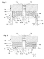
- the stamp 1a, b, c according to FIGS. 1, 2 and 3 contains a sleeve 2a, b, c made of a polyurethane, which is arranged on a carrier part 3a, b, c.
- the cuff 2a, b, c has a pocket-shaped recess 4a, b, c on the edge of an annular flange 5a, b, c and against the carrier part 3a, b, c through the end face 16a, b, c of a bottom part 15a, b, c is limited.
- a biasing plate 6a, b, c inserted from steel.
- Bias plate 6a, b, c, sleeve 2a, b, c and the support part 3a, b, c have a jointly aligned through opening 7a, b, c.
- a screw 8a, b, c from the direction of the biasing plate 6a, b, c
- the ring flange outer wall 12a, b, c tapers against Ring flange end face 13a, b, c, while the outer wall 19a, b, c of the bottom part 15a, b, c runs parallel to the longitudinal axis x of the stamp.
- the ring flange inner wall 14a according to the embodiment according to FIG. 1 is essentially parallel to the longitudinal axis x of the stamp.
- the edge is broken by means of a corner surface 17a, so that the ring flange 2a forms a foot-like widening towards the end face 16a with a maximum diameter e 1 .
- the maximum diameter e 1 of the foot-like widening corresponds approximately to the diameter d 1 of the ring flange 2a in the area of the ring flange end surface 13a.
- the maximum diameter e 1 of the foot-like widening corresponds to approximately half the height h 1 of the ring flange 2a or is greater.
- the edges at the transition from the corner surface 17a to the ring flange inner wall 14a and to the end surface 16a are rounded and are enclosed at an angle of approximately 135 ° to the adjacent walls or surfaces.
- the cuff 2a nestles against the walls 18 of the profile chamber 20 in the ready position of the stamp 1a.
- the edge is broken by means of a curved surface 17b, so that the ring flange 5b to the end face 16b forms a foot-like widening with a maximum diameter of e 2 .
- the radius r of the circle delimiting the curved surface corresponds approximately to half the height h 1 of the ring flange 2b or is greater.
- the maximum diameter e 2 of the foot-like widening in turn corresponds approximately to the diameter d 2 of the ring flange 2b in the area of the ring flange end face 13b.
- the maximum diameter e 2 of the foot-like widening corresponds approximately to half the height h 2 of the ring flange 2b or is greater.
- the cuff 2c nestles against the walls 18 of the profile chamber 20 in the operational position of the stamp 1c.
- a further embodiment of a stamp 1d according to the invention according to FIG. 4 contains one Cuff 2d made of a polyurethane, which is arranged on a carrier part 3d.
- the Cuff 2d contains groove-shaped or hole-shaped recesses 25 on its end face 16d.
- a prestressing plate 6d made of steel is arranged, which is part of the Contains recesses 25 corresponding formations 26.
- the projections 26 grip a perfect fit in the recesses 25 and secure the biasing plate 6d against rotation around the longitudinal axis x.
- the biasing plate 6d, the sleeve 2d and that Carrier part 3d have a jointly aligned through opening 7d.
- a screw 8d with a through hole from the direction of the biasing plate 6d 9d embedded, which with the screw head 10d on the biasing plate 6d abuts and is screwed and anchored via a thread 11d in the carrier plate 3d.
- the End section wall 12d tapers towards the end face 16d, while the outer wall 19d runs essentially parallel to the longitudinal axis x of the stamp.
- the biasing plate 6a, b, c, d according to Fig. 1, 2, 3 and 4 is before inserting the stamp 1a, b, c, d stretched into its operating position by the screw 8a, b, c, d, such that the sleeve 2a, b, c, d sandwiched between the biasing plate 6a, b, c, d and the carrier part 3a, b, c, d is squeezed and widened sideways.
- the measure of the created Tension and thus the degree of crushing and widening of the cuff 2a, b, c, d depends on the existing tolerances between sleeve 2a, b, c, d and Profile chamber walls 18.
- FIG. 5a shows a top view of a cuff 2h according to the embodiment of the invention.
- the same cuff 2h is in cross-sectional view through the line AA in FIG. 5b played.
- the outer wall 19h of the base part 15h describes a polygonal Floor plan, which with the cross-sectional geometry of a corresponding profile chamber 20 of a multi-chamber profile 21 corresponds (see FIG. 8).
- the through the outer wall 19h reproduced outer contour of the cuff 2h is 5h by an annular flange accompanied, which is shown in Fig. 5a by the ring flange end face 13h.
- the Ring flange 5h encloses a pocket-shaped recess 4h, which in FIG. 5a whose end face is visible for 16 hours.
- a through opening 7h is in a central arrangement for a screw connection with through-hole for a pressure medium supply and / or discharge channel intended.
- the edges in the transition area of two ring flange sections intersecting at an angle are rounded in the area of the inner ring flange wall 14h.
- Said transition area is preferably delimited by a curve piece with a circular radius s.
- the circle radius s corresponds to or is greater than half the diameter e 5 of the maximum foot-like widening of the ring flange 5h.
- the diameter d 5 of the ring flange end face 13h corresponds approximately to the maximum diameter e 5 of the foot-like widening.
- the outer wall 19h is parallel to the longitudinal axis x of the punch, while the ring flange outer wall 12h tapers towards the ring flange end face 13h.
- a wear protection is provided on the basis of the stamp 1e shown in FIG. 3.
- the Wear protection is in the form of a strip-shaped wear strip 30 at the transition the ring flange outer wall 12e to the outer wall 19e of the bottom part 15e in a groove-shaped recess 31 in the outer wall 19e of the bottom part 15e.
- the outer wall of the wear strip 30 is aligned with the outer wall 19e of the Bottom part 15e.
- the wear bar 30 is made of steel.
- FIG. 7 In a further embodiment of the invention according to FIG. 7 is based on a description Fig. 3 executed stamp 1f a wear protection is provided.
- a wear protection is provided between the carrier part 3f and the cuff 2f.
- the bead-like edge 36 forms wear protection on the outer wall 19f of the cuff 2f.
- the bead-like edge 36 has an in the outer surface 37 running to the outer wall 19f of the sleeve 2f.
- the outer surface 19f of the sleeve 2f tapers slightly in the direction of the ring flange 5f.
- the bead-like edge 36 thus forms a protruding into the outer wall 19f of the sleeve 2f Wear edge off.
- the intermediate part 35 also has one with the through opening 7f of the biasing plate 6f, the sleeve 2f and the carrier part 3f in alignment Through hole for the passage of a fastening screw 8f with a through hole 9f.
- the fastening means 8f anchoring the prestressing plate 4f can also be in the intermediate part 35 be anchored.
- the configuration of the ring flange 5e, f in FIGS. 6 and 7 and its walls 12e, f, 13e, f, 14e, f, 17e, f and in particular the design of the transition area from the Ring flange 14e, f to the end face 16e, f of the sleeve 2e, f and the anchoring the cuff 2e, f in the carrier part 3e, f corresponds to the explanations for Fig. 3. From the associated Corresponding features can be found in the description.
- the said Design of the ring flange 2f and its walls and in particular the design the transition area from the inner ring flange and the transition area can also correspond to FIGS. 1 and 2.
- the wear protection described above and its design variants also apply to the design variant belonging to FIG. 4 applicable.
Landscapes
- Physics & Mathematics (AREA)
- Fluid Mechanics (AREA)
- Engineering & Computer Science (AREA)
- Mechanical Engineering (AREA)
- Press-Shaping Or Shaping Using Conveyers (AREA)
- Blow-Moulding Or Thermoforming Of Plastics Or The Like (AREA)
- Shaping Of Tube Ends By Bending Or Straightening (AREA)
- Shaping Metal By Deep-Drawing, Or The Like (AREA)
- Golf Clubs (AREA)
- Moulds For Moulding Plastics Or The Like (AREA)
- Accessories Of Cameras (AREA)
Priority Applications (6)
| Application Number | Priority Date | Filing Date | Title |
|---|---|---|---|
| EP00810590A EP1170069A1 (fr) | 2000-07-05 | 2000-07-05 | Dispositif de formage par haute pression interne d' un profilé creux |
| EP20010810590 EP1170070B1 (fr) | 2000-07-05 | 2001-06-18 | Dispositif de formage par haute pression interne d' un profilé creux |
| ES01810590T ES2228784T3 (es) | 2000-07-05 | 2001-06-18 | Dispositivo para la transferencia de un perfil hueco por medio de transformacion de alta presion interior. |
| AT01810590T ATE283737T1 (de) | 2000-07-05 | 2001-06-18 | Vorrichtung zum umformen eines hohlprofils mittels innenhochdruck-umformens |
| DE50104660T DE50104660D1 (de) | 2000-07-05 | 2001-06-18 | Vorrichtung zum Umformen eines Hohlprofils mittels Innenhochdruck-Umformens |
| US09/899,465 US6575007B2 (en) | 2000-07-05 | 2001-07-05 | Device for forming a hollow profile by means of internal high pressure forming |
Applications Claiming Priority (1)
| Application Number | Priority Date | Filing Date | Title |
|---|---|---|---|
| EP00810590A EP1170069A1 (fr) | 2000-07-05 | 2000-07-05 | Dispositif de formage par haute pression interne d' un profilé creux |
Publications (1)
| Publication Number | Publication Date |
|---|---|
| EP1170069A1 true EP1170069A1 (fr) | 2002-01-09 |
Family
ID=8174789
Family Applications (1)
| Application Number | Title | Priority Date | Filing Date |
|---|---|---|---|
| EP00810590A Withdrawn EP1170069A1 (fr) | 2000-07-05 | 2000-07-05 | Dispositif de formage par haute pression interne d' un profilé creux |
Country Status (5)
| Country | Link |
|---|---|
| US (1) | US6575007B2 (fr) |
| EP (1) | EP1170069A1 (fr) |
| AT (1) | ATE283737T1 (fr) |
| DE (1) | DE50104660D1 (fr) |
| ES (1) | ES2228784T3 (fr) |
Cited By (1)
| Publication number | Priority date | Publication date | Assignee | Title |
|---|---|---|---|---|
| EP1475168A1 (fr) * | 2003-03-12 | 2004-11-10 | Forschungsgesellschaft Umformtechnik m.b.H. | Dispositif d'obturation des extrémités d'un profilé creux à utiliser dans un procédé de formage à haute pression interne |
Families Citing this family (2)
| Publication number | Priority date | Publication date | Assignee | Title |
|---|---|---|---|---|
| DE10347923B4 (de) * | 2003-10-15 | 2005-07-28 | Daimlerchrysler Ag | Vorrichtung zum Umformen eines umfänglich geschlossenen Hohlprofils mittels fluidischen Innenhochdrucks |
| US7305763B2 (en) * | 2005-07-26 | 2007-12-11 | Board Of Trustees Of Michigan State University | Hydroformed port liner |
Citations (5)
| Publication number | Priority date | Publication date | Assignee | Title |
|---|---|---|---|---|
| US2245887A (en) * | 1940-05-14 | 1941-06-17 | Gustavus A Wikander | Stopper for laundry tubs, washbasins, and other receptacles |
| DE1068206B (de) * | 1955-06-17 | 1959-11-05 | Flexonics Corporation, Maywood, 111. (V. St. A.) | Verfahren zum Herstellen eines gekrümmten Rohrformstückes |
| EP0225573A2 (fr) * | 1985-12-02 | 1987-06-16 | Aluminum Company Of America | Dispositif d'étanchéité pour les extrémités d'objets creux |
| US5038830A (en) * | 1986-06-27 | 1991-08-13 | Hydrotreat, Inc. | Pipe and sealing device |
| DE19909927A1 (de) * | 1999-03-06 | 2000-09-14 | Audi Ag | Vorrichtung zum Innenhochdruckumformen eines Hohlkörpers |
Family Cites Families (13)
| Publication number | Priority date | Publication date | Assignee | Title |
|---|---|---|---|---|
| US2837810A (en) * | 1955-06-17 | 1958-06-10 | Flexonics Corp | Method of producing fittings |
| US4393674A (en) * | 1981-06-25 | 1983-07-19 | Air-Mo Hydraulics, Inc. | Hydraulic chuck device for engagement with the inside of a tube |
| JPS61266132A (ja) * | 1985-05-21 | 1986-11-25 | Musashi Seimitsu Ind Co Ltd | 組立カムシヤフトの製造方法 |
| US4761982A (en) * | 1986-10-01 | 1988-08-09 | General Motors Corporation | Method and apparatus for forming a heat exchanger turbulator and tube |
| DE4103082A1 (de) * | 1991-02-01 | 1992-08-27 | Eichelberg & Co Gmbh H D | Verfahren zum hydrostatischen umformen von hohlkoerpern aus kaltumformbarem metall und vorrichtung zur durchfuehrung des verfahrens |
| US5170557A (en) * | 1991-05-01 | 1992-12-15 | Benteler Industries, Inc. | Method of forming a double wall, air gap exhaust duct component |
| US5233854A (en) * | 1992-05-11 | 1993-08-10 | General Motors Corporation | Press apparatus for hydroforming a tube |
| US5363544A (en) * | 1993-05-20 | 1994-11-15 | Benteler Industries, Inc. | Multi-stage dual wall hydroforming |
| US5644829A (en) * | 1993-08-16 | 1997-07-08 | T I Corporate Services Limited | Method for expansion forming of tubing |
| US6128936A (en) * | 1998-09-09 | 2000-10-10 | Kabushiki Kaisha Opton | Bulging device and bulging method |
| US6065502A (en) * | 1998-10-07 | 2000-05-23 | Cosma International Inc. | Method and apparatus for wrinkle-free hydroforming of angled tubular parts |
| JP3688921B2 (ja) * | 1999-01-14 | 2005-08-31 | 日産自動車株式会社 | 液圧成形ノズルおよび液圧成形装置 |
| US6279364B1 (en) * | 1999-02-16 | 2001-08-28 | Gary E. Morphy | Sealing method and press apparatus |
-
2000
- 2000-07-05 EP EP00810590A patent/EP1170069A1/fr not_active Withdrawn
-
2001
- 2001-06-18 AT AT01810590T patent/ATE283737T1/de not_active IP Right Cessation
- 2001-06-18 ES ES01810590T patent/ES2228784T3/es not_active Expired - Lifetime
- 2001-06-18 DE DE50104660T patent/DE50104660D1/de not_active Expired - Fee Related
- 2001-07-05 US US09/899,465 patent/US6575007B2/en not_active Expired - Fee Related
Patent Citations (5)
| Publication number | Priority date | Publication date | Assignee | Title |
|---|---|---|---|---|
| US2245887A (en) * | 1940-05-14 | 1941-06-17 | Gustavus A Wikander | Stopper for laundry tubs, washbasins, and other receptacles |
| DE1068206B (de) * | 1955-06-17 | 1959-11-05 | Flexonics Corporation, Maywood, 111. (V. St. A.) | Verfahren zum Herstellen eines gekrümmten Rohrformstückes |
| EP0225573A2 (fr) * | 1985-12-02 | 1987-06-16 | Aluminum Company Of America | Dispositif d'étanchéité pour les extrémités d'objets creux |
| US5038830A (en) * | 1986-06-27 | 1991-08-13 | Hydrotreat, Inc. | Pipe and sealing device |
| DE19909927A1 (de) * | 1999-03-06 | 2000-09-14 | Audi Ag | Vorrichtung zum Innenhochdruckumformen eines Hohlkörpers |
Cited By (1)
| Publication number | Priority date | Publication date | Assignee | Title |
|---|---|---|---|---|
| EP1475168A1 (fr) * | 2003-03-12 | 2004-11-10 | Forschungsgesellschaft Umformtechnik m.b.H. | Dispositif d'obturation des extrémités d'un profilé creux à utiliser dans un procédé de formage à haute pression interne |
Also Published As
| Publication number | Publication date |
|---|---|
| US6575007B2 (en) | 2003-06-10 |
| DE50104660D1 (de) | 2005-01-05 |
| ATE283737T1 (de) | 2004-12-15 |
| ES2228784T3 (es) | 2005-04-16 |
| US20020002851A1 (en) | 2002-01-10 |
Similar Documents
| Publication | Publication Date | Title |
|---|---|---|
| EP1391640B1 (fr) | Bague d'étanchéité | |
| DE102007039032A1 (de) | Niederzugspanner | |
| DE3423155C2 (fr) | ||
| DE3520653C2 (fr) | ||
| EP0807204A1 (fr) | Garniture d'etancheite pour segments de galeries de tunnel | |
| DE3430062C2 (fr) | ||
| EP1406737A2 (fr) | Procede et dispositif pour assembler des plaques superposees | |
| EP1060829B1 (fr) | Guidage linéaire | |
| DE19601288C2 (de) | Vorrichtung zum Abdichten eines von einem inneren und einem äußeren Körper begrenzten Ringraumes | |
| EP1170069A1 (fr) | Dispositif de formage par haute pression interne d' un profilé creux | |
| EP1170070B1 (fr) | Dispositif de formage par haute pression interne d' un profilé creux | |
| EP0939256B1 (fr) | Système d'étanchéité | |
| DE19832142C2 (de) | Verfahren und Vorrichtung zur Herstellung eines Hohlkörpers aus zwei Platinen | |
| EP1601835B1 (fr) | Coeur de croisement de rails a gorge | |
| DE2633443A1 (de) | Schieberventil | |
| DE19750120C1 (de) | Rohrdichtschelle | |
| DE3324833C2 (de) | Haltevorrichtung für rechteckige Düsenplatten | |
| DE102008033874A1 (de) | Druckgastank | |
| DE4419555C1 (de) | Stranggießer für Stranggießanlagen, insbesondere für thermoplastische Kunststoffe | |
| DE902123C (de) | Grubenstempel | |
| EP1231996B1 (fr) | Membrane-presse realisee dans un materiau elastique de type caoutchouc | |
| WO2018134108A1 (fr) | Rondelle, ensemble de fixation et utilisation de la rondelle | |
| DE3613705C2 (fr) | ||
| DE19905849C1 (de) | Vorrichtung zum Umformen eines Hohlprofils od. dgl. Werkstückes auf dem Wege dem Innenhochdruck-Umformens | |
| DE19815415A1 (de) | Dichtungsanordnung mit angepaßtem Rahmenprofil |
Legal Events
| Date | Code | Title | Description |
|---|---|---|---|
| PUAI | Public reference made under article 153(3) epc to a published international application that has entered the european phase |
Free format text: ORIGINAL CODE: 0009012 |
|
| AK | Designated contracting states |
Kind code of ref document: A1 Designated state(s): AT BE CH CY DE DK ES FI FR GB GR IE IT LI LU MC NL PT SE |
|
| AX | Request for extension of the european patent |
Free format text: AL;LT;LV;MK;RO;SI |
|
| AKX | Designation fees paid | ||
| REG | Reference to a national code |
Ref country code: DE Ref legal event code: 8566 |
|
| STAA | Information on the status of an ep patent application or granted ep patent |
Free format text: STATUS: THE APPLICATION IS DEEMED TO BE WITHDRAWN |
|
| 18D | Application deemed to be withdrawn |
Effective date: 20020710 |