EP1170091A2 - Outil de chanfreinage - Google Patents
Outil de chanfreinage Download PDFInfo
- Publication number
- EP1170091A2 EP1170091A2 EP01114535A EP01114535A EP1170091A2 EP 1170091 A2 EP1170091 A2 EP 1170091A2 EP 01114535 A EP01114535 A EP 01114535A EP 01114535 A EP01114535 A EP 01114535A EP 1170091 A2 EP1170091 A2 EP 1170091A2
- Authority
- EP
- European Patent Office
- Prior art keywords
- tool
- tool according
- intermediate piece
- countersinking
- plastic intermediate
- Prior art date
- Legal status (The legal status is an assumption and is not a legal conclusion. Google has not performed a legal analysis and makes no representation as to the accuracy of the status listed.)
- Granted
Links
- 239000004033 plastic Substances 0.000 claims abstract description 74
- 229920003023 plastic Polymers 0.000 claims abstract description 74
- 239000011248 coating agent Substances 0.000 claims abstract description 25
- 238000000576 coating method Methods 0.000 claims abstract description 25
- 239000011521 glass Substances 0.000 claims abstract description 19
- 238000013016 damping Methods 0.000 claims abstract description 9
- 238000009826 distribution Methods 0.000 claims description 12
- 238000004519 manufacturing process Methods 0.000 claims description 11
- 239000002826 coolant Substances 0.000 claims description 6
- 239000000853 adhesive Substances 0.000 claims description 3
- 230000001070 adhesive effect Effects 0.000 claims description 3
- 238000007654 immersion Methods 0.000 claims description 3
- 238000003754 machining Methods 0.000 claims description 3
- 239000000110 cooling liquid Substances 0.000 claims description 2
- 238000005553 drilling Methods 0.000 claims description 2
- 239000000463 material Substances 0.000 abstract description 11
- 238000000227 grinding Methods 0.000 description 15
- 239000010432 diamond Substances 0.000 description 7
- 229910003460 diamond Inorganic materials 0.000 description 6
- 230000005489 elastic deformation Effects 0.000 description 4
- 229920001971 elastomer Polymers 0.000 description 3
- 229920001343 polytetrafluoroethylene Polymers 0.000 description 3
- 239000004810 polytetrafluoroethylene Substances 0.000 description 3
- 239000005060 rubber Substances 0.000 description 3
- 239000004952 Polyamide Substances 0.000 description 2
- 230000008878 coupling Effects 0.000 description 2
- 238000010168 coupling process Methods 0.000 description 2
- 238000005859 coupling reaction Methods 0.000 description 2
- 230000005284 excitation Effects 0.000 description 2
- 238000000034 method Methods 0.000 description 2
- 229920002647 polyamide Polymers 0.000 description 2
- -1 polytetrafluoroethylene Polymers 0.000 description 2
- 229920001342 Bakelite® Polymers 0.000 description 1
- 239000004831 Hot glue Substances 0.000 description 1
- 238000009825 accumulation Methods 0.000 description 1
- 239000004637 bakelite Substances 0.000 description 1
- 230000015572 biosynthetic process Effects 0.000 description 1
- 244000145845 chattering Species 0.000 description 1
- 238000010276 construction Methods 0.000 description 1
- 230000018109 developmental process Effects 0.000 description 1
- 239000013013 elastic material Substances 0.000 description 1
- 238000007667 floating Methods 0.000 description 1
- 238000009415 formwork Methods 0.000 description 1
- 238000010438 heat treatment Methods 0.000 description 1
- 238000003780 insertion Methods 0.000 description 1
- 230000037431 insertion Effects 0.000 description 1
- 229920000642 polymer Polymers 0.000 description 1
- 239000011435 rock Substances 0.000 description 1
- 230000011218 segmentation Effects 0.000 description 1
- 238000005245 sintering Methods 0.000 description 1
- 239000007787 solid Substances 0.000 description 1
- 125000006850 spacer group Chemical group 0.000 description 1
- 238000011144 upstream manufacturing Methods 0.000 description 1
- 238000010792 warming Methods 0.000 description 1
Images


Classifications
-
- B—PERFORMING OPERATIONS; TRANSPORTING
- B24—GRINDING; POLISHING
- B24B—MACHINES, DEVICES, OR PROCESSES FOR GRINDING OR POLISHING; DRESSING OR CONDITIONING OF ABRADING SURFACES; FEEDING OF GRINDING, POLISHING, OR LAPPING AGENTS
- B24B9/00—Machines or devices designed for grinding edges or bevels on work or for removing burrs; Accessories therefor
- B24B9/02—Machines or devices designed for grinding edges or bevels on work or for removing burrs; Accessories therefor characterised by a special design with respect to properties of materials specific to articles to be ground
- B24B9/06—Machines or devices designed for grinding edges or bevels on work or for removing burrs; Accessories therefor characterised by a special design with respect to properties of materials specific to articles to be ground of non-metallic inorganic material, e.g. stone, ceramics, porcelain
- B24B9/08—Machines or devices designed for grinding edges or bevels on work or for removing burrs; Accessories therefor characterised by a special design with respect to properties of materials specific to articles to be ground of non-metallic inorganic material, e.g. stone, ceramics, porcelain of glass
-
- B—PERFORMING OPERATIONS; TRANSPORTING
- B24—GRINDING; POLISHING
- B24D—TOOLS FOR GRINDING, BUFFING OR SHARPENING
- B24D7/00—Bonded abrasive wheels, or wheels with inserted abrasive blocks, designed for acting otherwise than only by their periphery, e.g. by the front face; Bushings or mountings therefor
- B24D7/10—Bonded abrasive wheels, or wheels with inserted abrasive blocks, designed for acting otherwise than only by their periphery, e.g. by the front face; Bushings or mountings therefor with cooling provisions
-
- B—PERFORMING OPERATIONS; TRANSPORTING
- B24—GRINDING; POLISHING
- B24D—TOOLS FOR GRINDING, BUFFING OR SHARPENING
- B24D7/00—Bonded abrasive wheels, or wheels with inserted abrasive blocks, designed for acting otherwise than only by their periphery, e.g. by the front face; Bushings or mountings therefor
- B24D7/18—Wheels of special form
Definitions
- the present invention relates to a countersink tool according to the preamble of claim 1.
- the tapered zones of the holes serve here also the centering of the fastening devices. These subsidence must therefore be distinguished from subsidence, at best the deburring of cylindrical bores serve.
- Such glass panes are usually used over several such mounting holes attached so that with increasing Number of mounting holes provided in the glass pane the cost factor in the event of glass breakage also increases.
- the plastic adapter serves as a coupling between the work spindle and the abrasive coating and feeds the vibration excitation that occurs within, so to speak of its own volume, since it is compared to the others on the Vibration movement involved machine and tool components is relatively flexible. Nevertheless, it will Plastic intermediate piece at most in the elastic range deform because it is made of a pressure-resistant plastic, which always withstands the feed forces. As a more appropriate Plastic can be viewed, for example, bakelite. Nevertheless, materials such as rubber, polyamide, PTFE (polytetrafluoroethylene) and others conceivable.
- the present invention also does not occur the flexibility of the abrasive coating on the countersink tool, so that easily selected a plastic of the highest compressive strength can be.
- a basic principle of the invention is based on the Consideration that the internal damping of the plastic the machine tool, especially the spindle carrier and the tool spindle will bend significantly less under the present feed forces, as part of the respective Feeding of an elastic deformation of the plastic intermediate piece is picked up and consumed there.
- the Plastic adapter should be used in industrial Range of channels interspersed to a communicating Flow connection between a usually axial To make inflow channel and the grinding surface.
- the invention avoids, among other things, floating of the diamond coating, that comes about during processing, that small and very small chips of the glass removal clog the covering. These chips practically fill the gaps between the Diamonds and stick to the surface of the tool, so that the diamond tips are practically no longer in production the lowering can be involved. This condition will Usually not covered by machine tools, so that the feed drive despite the reduced grinding ability of the Grinding surface continues.
- the resulting high pressures can be combined with the elasticity not designed for this type of operation of the machines trigger the feared vibrations.
- the abrasive coating can between the added spaces not free the abrasive diamond independently, so that this operating condition is extremely uncomfortable.
- the invention provides a remedy here.
- the plastic adapter gives according to its pressure elastic properties and thus enables the release of the removal.
- the invention also takes into account the Course of the diamond sharpness over the service life of the tool.
- Another advantage of the invention is the adaptability different head angles of the countersink tool. This means the cone angle with which the Tool head facing the workpiece and its apex lies on the geometric axis of rotation of the countersinking tool.
- This head angle can range between 0 ° and 180 ° lie and thus an almost arbitrary value within this Take boundaries. With such countersinking tools however, a head angle of 0 ° as well as a head angle of 180 °.
- the head angle is preferably in the range between approximately 30 ° to about 130 °, preferably at about 120 °, provided there are subsidence for the fastening systems mentioned in the introduction want.
- a preferred embodiment differs of the invention in two embodiments.
- the plastic intermediate piece forms the tool head and sits centered on the front End of the tool neck.
- This embodiment has the advantage that the tool head, which is a relatively large distance from the tool spindle occupies, consists of the light plastic material and thus the countersink tool only to small vibration amplitudes stimulates.
- the alternative embodiment provides that both Plastic intermediate piece as well as tool neck each Plastic. Depending on the respective tool stress different plastics can be used become. It is also a one-piece and one-piece embodiment conceivable.
- the invention can also be used on a combination tool, in which a drill section in front of the countersink part is provided for the manufacture of the cylindrical bore in Workpiece. Immediately afterwards, that sets without changing tools Countersink part on the workpiece to the intended depth reduction manufacture.
- the plastic intermediate piece is the tool head forms, has a glued on the plastic intermediate piece Proven grinding surface. It can be done easily act as a bowl - shaped body over a suitable pressure-resistant and heat-resistant adhesive high Shear strength connected to the plastic tool head is.
- This bowl-shaped body can be made by a sintering process be made.
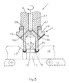
- the figures show a countersinking tool 1 for production of conical chamfers 13 on cylindrical bores 12 in Glass panes 10.
- a glass sheet 10 lies on one below the countersink tool 1 located pad 11 and is held there in a suitable manner while the countersink tool 1 rotating around the (here) vertical axis of rotation the glass pane 10 is lowered.
- Such countersinking tool has a tool neck 6, the end in the tool holder of a drive spindle a machine tool 4 is clamped in a rotationally fixed manner. On the Drive motor 3, the work spindle 2 is set in rotation. This rotary movement is possibly a suitable one Coupling at the end as a rotary movement in the tool neck 6 initiated where the drive end 5 is marked.
- the tool neck 6 has a tool head 7, which is equipped with a conical head angle 8 is.
- the tool head 7 has a conical inclined surface, on which the grinding pad 9 is attached. through this abrasive coating 9 is with the appropriate feed of the Countersinking tool 1 in the direction of the glass pane 10 13 central and concentric to the straight cylindrical Bore 12 introduced from one side.
- coolant supply 26 is carried out by a Axial channel, which extends from the tool neck 6 to the tool head 7 interspersed and there passes into a channel system 16a, b, c, d, that opens in the area of the grinding pad 9 on the tool head.
- the axial inflow channel 17 passes through the tool neck central to the axis of rotation so that the coolant supply 26 is constantly communicating with the abrasive coating.
- the abrasive coating 9 has a Plastic intermediate piece 14 rotatably with the drive spindle 2 is connected and that the plastic intermediate piece 14 with respect the feed forces acting in the direction of the cone tip 15 is pressure-resistant and also has good internal damping properties having.
- the plastic intermediate piece 14 follows in principle the head shape, which is defined by the cone tip 15 and has corresponding rotary drivers, via which it is rotatably connected to the drive spindle 2.
- a circumferential screw connection is used for this purpose, for example 27 according to the exemplary embodiments. Fig. 1, 3 and 5, by means of which the plastic intermediate piece 14 on the head side is struck on the tool neck 6.
- the circumferential screw connection 27 sits with a thread in a corresponding Tapped hole of the plastic intermediate piece 14 and engages with a tapered screw head corresponding recesses at the lower end of the tool neck 6 a form fit, so that the drive torque of the drive motor 3 directly into the plastic intermediate piece 14 can be initiated.
- the rotary driver realized by an adhesive joint 28 that runs as far as possible, the between the plastic intermediate piece 14 and the Pads of the tool neck is formed.
- the plastic intermediate piece 14 therefore forms a rotationally symmetrical solid component, which is on the grinding surface the conical head shape of the countersink tool and which on the tool neck side of the assigned rotationally symmetrical Formation of the straight cylindrical tool neck follows.
- the plastic intermediate piece 14 is related the feed forces acting in the direction of the cone tip 15 pressure-resistant and also has good internal damping properties on.
- At least the plastic intermediate piece 14 is such pressure-resistant that under the given feed forces during manufacture the subsidence of the abrasive coating 9 essentially is only exposed to compressive forces and therefore not elastic Deformation of the plastic adapter in the area of the active Grinding zone must follow.
- suitable materials can also be used as appropriate high Shore hardness levels also polyamide or polytetrafluoroethylene or comparable plastics use Find.
- the figures show plastic spacers 14, which are penetrated by channels 10 and 16a to d. This is necessary if you want a communicating flow connection between the abrasive coating 9 and the axial inflow channel 26 create the active grinding zone always and continuously to supply with coolant.
- the axial one opens out Inflow channel 14 also in a central distribution room 18, from which the radial channels 16a to 16d into the corresponding outlet openings in Continue sanding pad 9.
- Fig. 2 also shows a segmentation of the abrasive coating 9 in (here) four ring segments of the same size, which of respective recess grooves 19 are interrupted. On the ground of the recess grooves 19 open the respective radial Channels 16a to d, so that the cooling liquid of the head shape following the plastic intermediate piece 14 over the entire can distribute the active grinding zone.
- the central connection of the distribution channels is 16a to 16d to the axial inflow channel 17 of importance.
- the central distribution space 18 becomes an even supply all distribution channels 16a to 16d achieved, in principle is sufficient, the distribution channels 16a to 16d at the central To connect distribution room 18.
- An additional connection to the axial inflow channel 17, as shown, is not essential necessary.
- the figures show countersinking tools with head angles, that are smaller than 180 ° and larger than 0 °.
- the head angle is approximately 90 °.
- the invention is intended to be directed on head angle 8, which clearly has no faceplates with a Angle of 180 ° and no straight cylindrical discs are at an angle of 0 °.
- Figure 1 shows an embodiment, at which the plastic intermediate piece 14 the tool head 7th forms and centers on the front end of the tool neck 6 is scheduled.
- the centering consists of a pairing of the central Projection 20 and associated central recess 21 on the tool head or tool neck.
- the Depth 23 of the projection 20 is less than the depth 24 of the recess 21, so that the central distribution space 18 also at completely low intermediate piece 14 is created automatically.
- the relevant distribution channels 16a to 16d can consequently attached only in the plastic intermediate piece 14 be because the immersion depth 22 between the projection 20 and the recess 21 is less than the depth available 24 of the recess 21.
- the immersion depth 22 of the protrusion 20 is in the recess 21 limited by a depth stop so that the central distribution space 18 is created, both on the side the grinding pad 9 and on the side of the tool neck 6 communicates with a channel system for coolant.
- the depth stop is indicated by a Ring shoulder formed on the tool neck 6, against which the annular end face of the plastic intermediate piece 14 under Tighten the circumferential screw connection 27 pressure-tight.
- the channel system can be provided for the active grinding zone 16a to 16d on the side of the abrasive coating 9 in at least two to allow different radii to flow. This requirement is made possible by the basically conical tool head. All distribution channels 16a to 16d should be in the area the recess grooves 19 on the top surface of the plastic intermediate piece 14 mouth.
- both the plastic intermediate piece 14 as the tool neck 6 are made of plastic.
- the entire countersinking tool is in the exemplary embodiment according to FIG made in one piece and one piece from plastic and can therefore be referred to as a plastic intermediate piece 14 become.
- FIG. 5 shows an exemplary embodiment, in which the tool neck 6 the entire plastic intermediate piece 14 penetrated towards the cone tip 15 and towering over them a bit.
- the tool neck 6 forms one there straight ring cylinder, which has an abrasive on the end face Topping B. is sintered. Do you do that? Tool in the direction of a glass sheet 10, so first once drilled the straight cylindrical hole, which then from the downstream countersink tool with the countersink is provided.
- the covering can be on the Plastic intermediate piece can be glued on. To this end two-component or hot glue could be used.
Landscapes
- Engineering & Computer Science (AREA)
- Mechanical Engineering (AREA)
- Chemical & Material Sciences (AREA)
- Ceramic Engineering (AREA)
- Inorganic Chemistry (AREA)
- Polishing Bodies And Polishing Tools (AREA)
- Processing Of Stones Or Stones Resemblance Materials (AREA)
Applications Claiming Priority (2)
| Application Number | Priority Date | Filing Date | Title |
|---|---|---|---|
| DE10032036A DE10032036A1 (de) | 2000-07-05 | 2000-07-05 | Senkerwerkzeug |
| DE10032036 | 2000-07-05 |
Publications (3)
| Publication Number | Publication Date |
|---|---|
| EP1170091A2 true EP1170091A2 (fr) | 2002-01-09 |
| EP1170091A3 EP1170091A3 (fr) | 2002-10-30 |
| EP1170091B1 EP1170091B1 (fr) | 2005-08-10 |
Family
ID=7647440
Family Applications (1)
| Application Number | Title | Priority Date | Filing Date |
|---|---|---|---|
| EP01114535A Expired - Lifetime EP1170091B1 (fr) | 2000-07-05 | 2001-06-16 | Outil de chanfreinage |
Country Status (4)
| Country | Link |
|---|---|
| US (1) | US20020004362A1 (fr) |
| EP (1) | EP1170091B1 (fr) |
| DE (2) | DE10032036A1 (fr) |
| ES (1) | ES2246963T3 (fr) |
Cited By (8)
| Publication number | Priority date | Publication date | Assignee | Title |
|---|---|---|---|---|
| DE102007000208A1 (de) * | 2006-04-05 | 2007-10-11 | Denso Corporation, Kariya | Schleifapparat mit Schlammentfernungsvorrichtung und Schlammentfernungsverfahren |
| FR2946908A1 (fr) * | 2009-06-18 | 2010-12-24 | Peugeot Citroen Automobiles Sa | Procede et outil pour obtenir une culasse de cylindre finie |
| CN107322469A (zh) * | 2017-08-30 | 2017-11-07 | 苏州安洁科技股份有限公司 | 一种带有抛光功能的玻璃磨头 |
| CN107837879A (zh) * | 2017-10-31 | 2018-03-27 | 王明法 | 一种粉末涂料筛选研磨装置 |
| CN108942697A (zh) * | 2017-05-26 | 2018-12-07 | 通用电气公司 | 抛光工具及其制造方法 |
| CN109434611A (zh) * | 2018-12-26 | 2019-03-08 | 贰陆光学(苏州)有限公司 | 镜片倒角装置 |
| EP3419785A4 (fr) * | 2016-02-26 | 2019-09-04 | 3M Innovative Properties Company | Article abrasif amorti |
| CN114227430A (zh) * | 2021-11-26 | 2022-03-25 | 绍兴市舜海铜材有限公司 | 一种金属管件自动去毛刺装置 |
Families Citing this family (11)
| Publication number | Priority date | Publication date | Assignee | Title |
|---|---|---|---|---|
| AT5265U1 (de) * | 2001-07-27 | 2002-05-27 | Schraml Glastechnik Gmbh | Diamant-hohlbohrer |
| DE20212640U1 (de) | 2002-08-09 | 2002-10-31 | Bohle AG, 42781 Haan | Senkwerkzeug zum Säumen von Bohrungen in Glas sowie Schleifhut |
| US7125328B1 (en) | 2005-09-10 | 2006-10-24 | Michael Hacikyan | Glass grinding bit |
| DE202006018176U1 (de) * | 2006-11-30 | 2007-03-29 | Gunther Schwarz Gmbh | Instandsetzungswerkzeug |
| DE102007034140B4 (de) * | 2006-11-30 | 2011-05-12 | Gunther Schwarz Gmbh | Instandsetzungswerkzeug |
| DE102011076649B4 (de) * | 2011-05-27 | 2026-05-07 | Schaeffler Technologies AG & Co. KG | Schleifstift zum Schleifen einer Innenoberfläche eines Hohlraumes |
| JP6698073B2 (ja) * | 2014-08-26 | 2020-05-27 | スリーエム イノベイティブ プロパティズ カンパニー | ダンパー付き研磨カッター |
| US9844853B2 (en) | 2014-12-30 | 2017-12-19 | Saint-Gobain Abrasives, Inc./Saint-Gobain Abrasifs | Abrasive tools and methods for forming same |
| CA3009791A1 (fr) | 2015-12-30 | 2017-07-06 | Saint-Gobain Abrasives, Inc. | Outils abrasifs et leurs procedes de formation |
| WO2018183724A1 (fr) * | 2017-03-31 | 2018-10-04 | Saint-Gobain Abrasives, Inc. | Ensemble meule |
| MX2021004489A (es) | 2018-10-19 | 2021-06-04 | Saint Gobain Abrasives Inc | Montaje de muelas de rectificar. |
Family Cites Families (4)
| Publication number | Priority date | Publication date | Assignee | Title |
|---|---|---|---|---|
| BE718357A (fr) * | 1968-07-19 | 1968-12-31 | ||
| DE4024399A1 (de) * | 1990-08-01 | 1992-02-06 | Hilti Ag | Bohrwerkzeug |
| US5993297A (en) * | 1994-09-06 | 1999-11-30 | Makino Inc. | Superabrasive grinding wheel with integral coolant passage |
| NZ501168A (en) * | 1997-06-17 | 2001-06-29 | Norton Co | Method and drilling apparatus coupled to a non-metallic body (e.g. PVC, nylon or acrylic) to reduced vibrations during operation |
-
2000
- 2000-07-05 DE DE10032036A patent/DE10032036A1/de not_active Withdrawn
-
2001
- 2001-06-16 EP EP01114535A patent/EP1170091B1/fr not_active Expired - Lifetime
- 2001-06-16 DE DE50107018T patent/DE50107018D1/de not_active Expired - Lifetime
- 2001-06-16 ES ES01114535T patent/ES2246963T3/es not_active Expired - Lifetime
- 2001-06-29 US US09/896,668 patent/US20020004362A1/en not_active Abandoned
Cited By (10)
| Publication number | Priority date | Publication date | Assignee | Title |
|---|---|---|---|---|
| DE102007000208A1 (de) * | 2006-04-05 | 2007-10-11 | Denso Corporation, Kariya | Schleifapparat mit Schlammentfernungsvorrichtung und Schlammentfernungsverfahren |
| DE102007000208B4 (de) * | 2006-04-05 | 2010-11-04 | DENSO CORPORATION, Kariya-shi | Schleifapparat und Schleifverfahren |
| FR2946908A1 (fr) * | 2009-06-18 | 2010-12-24 | Peugeot Citroen Automobiles Sa | Procede et outil pour obtenir une culasse de cylindre finie |
| EP3419785A4 (fr) * | 2016-02-26 | 2019-09-04 | 3M Innovative Properties Company | Article abrasif amorti |
| CN108942697A (zh) * | 2017-05-26 | 2018-12-07 | 通用电气公司 | 抛光工具及其制造方法 |
| CN107322469A (zh) * | 2017-08-30 | 2017-11-07 | 苏州安洁科技股份有限公司 | 一种带有抛光功能的玻璃磨头 |
| CN107837879A (zh) * | 2017-10-31 | 2018-03-27 | 王明法 | 一种粉末涂料筛选研磨装置 |
| CN109434611A (zh) * | 2018-12-26 | 2019-03-08 | 贰陆光学(苏州)有限公司 | 镜片倒角装置 |
| CN114227430A (zh) * | 2021-11-26 | 2022-03-25 | 绍兴市舜海铜材有限公司 | 一种金属管件自动去毛刺装置 |
| CN114227430B (zh) * | 2021-11-26 | 2022-10-11 | 绍兴市舜海铜材有限公司 | 一种金属管件自动去毛刺装置 |
Also Published As
| Publication number | Publication date |
|---|---|
| EP1170091A3 (fr) | 2002-10-30 |
| US20020004362A1 (en) | 2002-01-10 |
| DE10032036A1 (de) | 2002-01-17 |
| DE50107018D1 (de) | 2005-09-15 |
| EP1170091B1 (fr) | 2005-08-10 |
| ES2246963T3 (es) | 2006-03-01 |
Similar Documents
| Publication | Publication Date | Title |
|---|---|---|
| EP1170091B1 (fr) | Outil de chanfreinage | |
| DE69228984T2 (de) | Verschleissfeste Werkzeuge | |
| DE102006016290C5 (de) | Mehrteiliges Schaftwerkzeug, insbesondere Feinbearbeitungswerkzeug | |
| DE102009048010B3 (de) | Werkzeuginterface | |
| DE3610016C2 (fr) | ||
| WO1997017153A1 (fr) | Outil de perçage avec pointe remplaçable | |
| WO2002076661A1 (fr) | Outil et ensemble outil | |
| WO2011015259A1 (fr) | Support d'outil avec porte-outils interchangeables et porte-outil | |
| DE102006005379A1 (de) | Kombinationswerkzeug und Verfahren zur spanenden Bearbeitung eines Bohrlochs und dessen Bohrungsoberfläche sowie Schneidkörper für ein derartiges Kombinationswerkzeug | |
| EP3837076B1 (fr) | Outil de chanfreinage | |
| EP2509745A1 (fr) | Module pour l'équipement ultérieur d'un dispositif de meulage d'électrodes et dispositif de meulage d'électrodes | |
| DE20204848U1 (de) | Auswechselbare Bohrerspitze und Bohrwerkzeuganordnung | |
| EP2489488A1 (fr) | Scie de forage à diamant dotée d'un foreur central et d'une butée | |
| EP2448705B1 (fr) | Outil pour l'usinage ou la réalisation d'un trou chanfreiné | |
| EP1414608B1 (fr) | Outil et procede pour la finition de sieges et de guides de soupapes | |
| DE102004031600B4 (de) | Werkzeug zur Bearbeitung eines mineralischen Untergrundes mit einem Ultraschall-Werkzeuggerät | |
| DE102006007787A1 (de) | Vorrichtung und Verfahren zum spanabhebenden Herstellen einer kalottenförmigen Ausnehmung in einem Werkstück | |
| DE102004008166A1 (de) | Werkzeug zur spanenden Bearbeitung von Präzisionsbohrungen | |
| EP1211016B1 (fr) | Outil à forer des trous profonds et son procédé de fabrication | |
| EP4005713A2 (fr) | Outil de déchiquetage permettant d'usiner la matière plastique | |
| EP1740338A1 (fr) | Outil a brocher et procede pour usiner des surfaces de trous, par enlevement de matiere | |
| DE19841579C2 (de) | Werkzeug zur spanenden Bearbeitung mit geometrisch bestimmten Schneiden | |
| DE2204137A1 (de) | Planeinstechwerkzeug | |
| DD280272A1 (de) | Messerkopf mit schrupp- und schlichtschneiden | |
| AT409353B (de) | Fräswerkzeug |
Legal Events
| Date | Code | Title | Description |
|---|---|---|---|
| PUAI | Public reference made under article 153(3) epc to a published international application that has entered the european phase |
Free format text: ORIGINAL CODE: 0009012 |
|
| AK | Designated contracting states |
Kind code of ref document: A2 Designated state(s): AT BE CH CY DE DK ES FI FR GB GR IE IT LI LU MC NL PT SE TR |
|
| AX | Request for extension of the european patent |
Free format text: AL;LT;LV;MK;RO;SI |
|
| PUAL | Search report despatched |
Free format text: ORIGINAL CODE: 0009013 |
|
| AK | Designated contracting states |
Kind code of ref document: A3 Designated state(s): AT BE CH CY DE DK ES FI FR GB GR IE IT LI LU MC NL PT SE TR |
|
| AX | Request for extension of the european patent |
Free format text: AL;LT;LV;MK;RO;SI |
|
| 17P | Request for examination filed |
Effective date: 20030319 |
|
| AKX | Designation fees paid |
Designated state(s): BE DE ES FR GB IT |
|
| 17Q | First examination report despatched |
Effective date: 20040628 |
|
| GRAP | Despatch of communication of intention to grant a patent |
Free format text: ORIGINAL CODE: EPIDOSNIGR1 |
|
| GRAS | Grant fee paid |
Free format text: ORIGINAL CODE: EPIDOSNIGR3 |
|
| GRAA | (expected) grant |
Free format text: ORIGINAL CODE: 0009210 |
|
| AK | Designated contracting states |
Kind code of ref document: B1 Designated state(s): BE DE ES FR GB IT |
|
| REG | Reference to a national code |
Ref country code: GB Ref legal event code: FG4D Free format text: NOT ENGLISH |
|
| GBT | Gb: translation of ep patent filed (gb section 77(6)(a)/1977) |
Effective date: 20050810 |
|
| REF | Corresponds to: |
Ref document number: 50107018 Country of ref document: DE Date of ref document: 20050915 Kind code of ref document: P |
|
| REG | Reference to a national code |
Ref country code: ES Ref legal event code: FG2A Ref document number: 2246963 Country of ref document: ES Kind code of ref document: T3 |
|
| ET | Fr: translation filed | ||
| PLBE | No opposition filed within time limit |
Free format text: ORIGINAL CODE: 0009261 |
|
| STAA | Information on the status of an ep patent application or granted ep patent |
Free format text: STATUS: NO OPPOSITION FILED WITHIN TIME LIMIT |
|
| 26N | No opposition filed |
Effective date: 20060511 |
|
| REG | Reference to a national code |
Ref country code: DE Ref legal event code: R082 Ref document number: 50107018 Country of ref document: DE |
|
| REG | Reference to a national code |
Ref country code: FR Ref legal event code: PLFP Year of fee payment: 16 |
|
| REG | Reference to a national code |
Ref country code: FR Ref legal event code: PLFP Year of fee payment: 17 |
|
| REG | Reference to a national code |
Ref country code: FR Ref legal event code: PLFP Year of fee payment: 18 |
|
| PGFP | Annual fee paid to national office [announced via postgrant information from national office to epo] |
Ref country code: DE Payment date: 20180605 Year of fee payment: 18 |
|
| PGFP | Annual fee paid to national office [announced via postgrant information from national office to epo] |
Ref country code: BE Payment date: 20180417 Year of fee payment: 18 Ref country code: FR Payment date: 20180511 Year of fee payment: 18 |
|
| PGFP | Annual fee paid to national office [announced via postgrant information from national office to epo] |
Ref country code: ES Payment date: 20180702 Year of fee payment: 18 Ref country code: IT Payment date: 20180625 Year of fee payment: 18 Ref country code: GB Payment date: 20180403 Year of fee payment: 18 |
|
| REG | Reference to a national code |
Ref country code: DE Ref legal event code: R119 Ref document number: 50107018 Country of ref document: DE |
|
| GBPC | Gb: european patent ceased through non-payment of renewal fee |
Effective date: 20190616 |
|
| REG | Reference to a national code |
Ref country code: BE Ref legal event code: MM Effective date: 20190630 |
|
| PG25 | Lapsed in a contracting state [announced via postgrant information from national office to epo] |
Ref country code: IT Free format text: LAPSE BECAUSE OF NON-PAYMENT OF DUE FEES Effective date: 20190616 Ref country code: GB Free format text: LAPSE BECAUSE OF NON-PAYMENT OF DUE FEES Effective date: 20190616 Ref country code: DE Free format text: LAPSE BECAUSE OF NON-PAYMENT OF DUE FEES Effective date: 20200101 |
|
| PG25 | Lapsed in a contracting state [announced via postgrant information from national office to epo] |
Ref country code: BE Free format text: LAPSE BECAUSE OF NON-PAYMENT OF DUE FEES Effective date: 20190630 |
|
| PG25 | Lapsed in a contracting state [announced via postgrant information from national office to epo] |
Ref country code: FR Free format text: LAPSE BECAUSE OF NON-PAYMENT OF DUE FEES Effective date: 20190630 |
|
| REG | Reference to a national code |
Ref country code: ES Ref legal event code: FD2A Effective date: 20201028 |
|
| PG25 | Lapsed in a contracting state [announced via postgrant information from national office to epo] |
Ref country code: ES Free format text: LAPSE BECAUSE OF NON-PAYMENT OF DUE FEES Effective date: 20190617 |