EP4005713A2 - Outil de déchiquetage permettant d'usiner la matière plastique - Google Patents
Outil de déchiquetage permettant d'usiner la matière plastique Download PDFInfo
- Publication number
- EP4005713A2 EP4005713A2 EP21206884.5A EP21206884A EP4005713A2 EP 4005713 A2 EP4005713 A2 EP 4005713A2 EP 21206884 A EP21206884 A EP 21206884A EP 4005713 A2 EP4005713 A2 EP 4005713A2
- Authority
- EP
- European Patent Office
- Prior art keywords
- cutting
- tool
- shank
- hollow cylinder
- cutting tool
- Prior art date
- Legal status (The legal status is an assumption and is not a legal conclusion. Google has not performed a legal analysis and makes no representation as to the accuracy of the status listed.)
- Withdrawn
Links
Images

Classifications
-
- B—PERFORMING OPERATIONS; TRANSPORTING
- B23—MACHINE TOOLS; METAL-WORKING NOT OTHERWISE PROVIDED FOR
- B23B—TURNING; BORING
- B23B51/00—Tools for drilling machines
- B23B51/04—Drills for trepanning
- B23B51/0466—Drills for trepanning with exchangeable cutting inserts, e.g. able to be clamped
-
- B—PERFORMING OPERATIONS; TRANSPORTING
- B23—MACHINE TOOLS; METAL-WORKING NOT OTHERWISE PROVIDED FOR
- B23B—TURNING; BORING
- B23B2226/00—Materials of tools or workpieces not comprising a metal
- B23B2226/61—Plastics not otherwise provided for, e.g. nylon
-
- B—PERFORMING OPERATIONS; TRANSPORTING
- B23—MACHINE TOOLS; METAL-WORKING NOT OTHERWISE PROVIDED FOR
- B23B—TURNING; BORING
- B23B2260/00—Details of constructional elements
- B23B2260/124—Screws
-
- B—PERFORMING OPERATIONS; TRANSPORTING
- B23—MACHINE TOOLS; METAL-WORKING NOT OTHERWISE PROVIDED FOR
- B23B—TURNING; BORING
- B23B51/00—Tools for drilling machines
- B23B51/04—Drills for trepanning
- B23B51/042—Drills for trepanning with lubricating or cooling equipment
Definitions
- the invention relates to a cutting tool for machining plastic according to the independent claim.
- the invention lies in the technical field of tools for metal-cutting production processes, in particular drills for producing bores in plastic, such as carbon-fibre-reinforced plastic.
- drills with different diameters for producing bores of different sizes.
- the most commonly used drills are twist drills or helical drills or helical flute drills.
- the drill diameters to be produced are often in the range of 10-60 mm.
- particular attention is paid to avoiding delamination and fiber protrusions at the exit of the hole and to maintaining the entire hole tolerances in terms of diameter, shape and surface in a process-reliable manner.
- the object of the invention is to provide a cutting tool that overcomes the disadvantages of the prior art and enables larger bores to be produced with good quality with a minimum number of process steps.
- the invention comprises a cutting tool for machining plastic, comprising a tool shank for arrangement in a tool holder and a hollow cylinder adjoining the tool shank, comprising at least one cutting element arranged on the front side so that it can be removed.
- the cutting tool is inserted into the drill chuck of a drill, which usually performs a rotary motion about its axis, thereby moving the cutting tool into the workpiece to be machined.
- the hollow cylinder has at least one opening on the front side for receiving the cutting element. This allows the cutting element to be easily replaced when worn. This enables delamination to be avoided and allows for the production of holes of the highest quality surface finish.
- the worn cutting element can also simply be reground and reinstalled. This enables multiple use of the cutting elements and thus sustainable use of the materials used for the cutting elements.
- the cutting element comprises a shank with a length l 1 for arrangement in the opening and a cutting plate.
- the cutting insert has a cutting edge profile with a point. This ensures improved entry into and exit from the material.
- the hollow cylinder has a coolant outlet on the end face. This enables optimal cooling in the area of the machined area and thus an increase in the machining quality, with low coolant consumption at the same time.
- the shank has a circular cross-section with a flattening. This enables the cutting element to be easily removed and inserted into the cutting tool. As a result, the corresponding cutting element can be held or clamped firmly in a specific position.
- a coolant channel extending between the coolant outlet and a valve is formed between the opening and the shaft in the region of the flattening of the circular cross section.
- the cutting plate has a cross section that is larger than the cross section of the shank. This allows the cutting insert to rest on the hollow cylinder at the front, which allows the cutting insert to penetrate safely the material allows. This means that bores with larger diameters can be produced in a single process step because the hollow cylinder is inside the bore.
- the hollow cylinder comprises a recess arranged around each cutting element on the front side. As a result, the removed chips can be removed immediately.
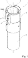
- a drilling tool 1 according to the invention is shown with a tool shank 2 and a hollow cylinder 3 (drill head, drill bit), the diameter of the tool shank 2 being smaller than the diameter of the hollow cylinder 3.
- three cutting elements 5 are arranged on the end face of the hollow cylinder 3.
- the recess 4 is arranged directly adjacent to the cutting element 5 . This results in a wave-like profile of the end face of the hollow cylinder 3, with the cutting elements 5 as an elevation and the corresponding recesses 4 as a depression.
- Recesses with two bores 7 can be seen on the outer circumference of the hollow cylinder 3 , through which the cutting elements 5 are fixed in the hollow cylinder 3 will.
- a in 1 illustrated drilling tool 1 according to the invention can be attached to the tool shank 2 in the drill chuck of a drill. With such an arrangement, a speed of 446 m/min can be achieved at a spindle speed of 3500 rpm.
- the feed rate of the drilling machine with a drilling tool 1 according to the invention is 250 mm/min, so process times of 5.2 seconds can be achieved.
- drilling diameters are produced in a range of 10-60 mm, preferably in the range of 20-40 mm. The drill penetrates the workpiece to a depth of 21.5 mm.
- the tool shank 2 has a smaller diameter than the hollow cylinder 3 .
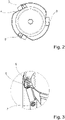
- a drilling tool 1 according to the invention is shown in a plan view from above.
- two cutting elements 5 are arranged on the end faces of the hollow cylinder 3 .
- no cutting element 5 is arranged in a third opening 8 .
- the recess 4 is arranged directly adjacent to the cutting element 5 or the corresponding opening 8 into which the cutting element 5 can be inserted. This results in a wave-like profile of the end face of the hollow cylinder 3, with the cutting elements 5 as an elevation and the corresponding recesses 4 as a depression.
- 8 cutting elements 5 can be inserted into the opening. If a cutting element is worn out after a certain number of machining cycles, it can simply be removed and ground again.
- FIG. 4 a side view of a cutting element 5 with a shank 11 of length I 1 and a cutting tip 12 with a cutting edge profile 13 and a tip 14 is shown.
- the length I 1 is chosen so that the shank 11 can be introduced completely into the opening 8 and the cutting tip 12 rests on the hollow cylinder 3 .
- the shank 11 has a profile at the end opposite the cutting plate 12. This profile serves to align the cutting element 5 in the opening 8.
- the cutting element 5 can be made of polycrystalline diamond.
- FIG 5 shows a side view of the upper section of a cutting element 5 with a cutting tip 12 with a cutting edge profile 13 and a tip 14.
- the tip 14 forms the highest point of the cutting edge profile 13 and thus first penetrates into the workpiece to be machined.
- the cutting plate 12 is connected to the shank 11 of the cutting element.
- the connection between the shank 11 and the cutting plate 12 can, for example, be a soldered or glued connection.
- the cutting element 5 is designed in two parts, consisting of a cutting insert 12 and the shank 11 .
- the cutting edge profile can be designed differently depending on the application.
Landscapes
- Engineering & Computer Science (AREA)
- Mechanical Engineering (AREA)
- Drilling Tools (AREA)
- Milling Processes (AREA)
Applications Claiming Priority (1)
| Application Number | Priority Date | Filing Date | Title |
|---|---|---|---|
| DE102020130445.5A DE102020130445A1 (de) | 2020-11-18 | 2020-11-18 | Zerspanungswerkzeug zum Bearbeiten von Kunststoff |
Publications (2)
| Publication Number | Publication Date |
|---|---|
| EP4005713A2 true EP4005713A2 (fr) | 2022-06-01 |
| EP4005713A3 EP4005713A3 (fr) | 2022-06-08 |
Family
ID=78536134
Family Applications (1)
| Application Number | Title | Priority Date | Filing Date |
|---|---|---|---|
| EP21206884.5A Withdrawn EP4005713A3 (fr) | 2020-11-18 | 2021-11-08 | Outil de déchiquetage permettant d'usiner la matière plastique |
Country Status (2)
| Country | Link |
|---|---|
| EP (1) | EP4005713A3 (fr) |
| DE (1) | DE102020130445A1 (fr) |
Families Citing this family (1)
| Publication number | Priority date | Publication date | Assignee | Title |
|---|---|---|---|---|
| DE102022121237A1 (de) | 2022-08-23 | 2024-02-29 | Gühring KG | Bohrvorrichtung mit einer Absaugeinheit |
Citations (2)
| Publication number | Priority date | Publication date | Assignee | Title |
|---|---|---|---|---|
| US4500234A (en) | 1982-11-12 | 1985-02-19 | Waukesha Cutting Tools, Inc. | Trepanning tool |
| US5451128A (en) | 1994-01-29 | 1995-09-19 | T. D. Williamson, S.A. | Cutter tool having removable teeth |
Family Cites Families (3)
| Publication number | Priority date | Publication date | Assignee | Title |
|---|---|---|---|---|
| SU1068237A1 (ru) * | 1981-01-12 | 1984-01-23 | Брянский Ордена "Знак Почета" Институт Транспортного Машиностроения | Кольцевое сверло |
| DE202007017299U1 (de) * | 2007-12-12 | 2009-04-23 | Drebo Werkzeugfabrik Gmbh | Bohrer |
| CN104148709A (zh) * | 2014-06-30 | 2014-11-19 | 江阴乐高能源装备有限公司 | 一种套料刀具 |
-
2020
- 2020-11-18 DE DE102020130445.5A patent/DE102020130445A1/de not_active Ceased
-
2021
- 2021-11-08 EP EP21206884.5A patent/EP4005713A3/fr not_active Withdrawn
Patent Citations (2)
| Publication number | Priority date | Publication date | Assignee | Title |
|---|---|---|---|---|
| US4500234A (en) | 1982-11-12 | 1985-02-19 | Waukesha Cutting Tools, Inc. | Trepanning tool |
| US5451128A (en) | 1994-01-29 | 1995-09-19 | T. D. Williamson, S.A. | Cutter tool having removable teeth |
Also Published As
| Publication number | Publication date |
|---|---|
| DE102020130445A1 (de) | 2022-05-19 |
| EP4005713A3 (fr) | 2022-06-08 |
Similar Documents
| Publication | Publication Date | Title |
|---|---|---|
| EP2560778B1 (fr) | Tête de forage pour un outil de forage profond destiné au forage profond bta et outil de forage profond | |
| DE69621030T3 (de) | Böhrer mit Kühlkanälen und Verfahren zu seiner Herstellung | |
| DE102011106416B4 (de) | Bohr-Reib-Werkzeug | |
| DE69926067T2 (de) | Schneidwerkzeug mit vergrössertem diameter und reduzierter länge des kopfes für faser verstärkte verbundmaterialien | |
| DE102004059264B4 (de) | Werkzeug und Verfahren zur Erzeugung eines Gewindes in einem Werkstück | |
| DE102010006796B4 (de) | Verfahren zur Herstellung eines Bohrers, sowie Bohrer | |
| EP2550126B1 (fr) | Alésoir avec canaux de refroidissement | |
| EP2670550B9 (fr) | Outil de forage et procede de fabrication de trous | |
| DE102012002050A1 (de) | Kombiniertes Bohr- und Räumer-Werkzeug | |
| EP2260965A2 (fr) | Fraise forante de filetage | |
| EP2635394A1 (fr) | Foret à langue d'aspic | |
| DE102019102726A1 (de) | Bohrwerkzeug und Verfahren zur Erzeugung einer Bohrung | |
| EP2448704B1 (fr) | Foret pour forage profond | |
| DE4228322A1 (de) | Bohrfräser | |
| DE102014207502A1 (de) | Rotationswerkzeug sowie Werkzeugkopf | |
| EP3204180B1 (fr) | Outil de perçage, en particulier alésoir | |
| DE10144241A1 (de) | Bohrer | |
| EP3743234A1 (fr) | Outil de fraisage | |
| DE10321670A1 (de) | Werkzeug, Vorrichtung und Verfahren zum Entgraten von Bohrungen | |
| EP4005713A2 (fr) | Outil de déchiquetage permettant d'usiner la matière plastique | |
| EP1382410B2 (fr) | Foret | |
| EP0258660B1 (fr) | Fleuret plein à une lèvre de coupe | |
| EP2915613B1 (fr) | Foret à trou transversal | |
| DE102009033508B4 (de) | Einlippenbohrer | |
| DE10144735B4 (de) | Schneideinsätze und Rotations-Umfangsfräser mit austauschbaren Schneideinsätzen |
Legal Events
| Date | Code | Title | Description |
|---|---|---|---|
| PUAI | Public reference made under article 153(3) epc to a published international application that has entered the european phase |
Free format text: ORIGINAL CODE: 0009012 |
|
| STAA | Information on the status of an ep patent application or granted ep patent |
Free format text: STATUS: THE APPLICATION HAS BEEN PUBLISHED |
|
| PUAL | Search report despatched |
Free format text: ORIGINAL CODE: 0009013 |
|
| AK | Designated contracting states |
Kind code of ref document: A2 Designated state(s): AL AT BE BG CH CY CZ DE DK EE ES FI FR GB GR HR HU IE IS IT LI LT LU LV MC MK MT NL NO PL PT RO RS SE SI SK SM TR |
|
| AK | Designated contracting states |
Kind code of ref document: A3 Designated state(s): AL AT BE BG CH CY CZ DE DK EE ES FI FR GB GR HR HU IE IS IT LI LT LU LV MC MK MT NL NO PL PT RO RS SE SI SK SM TR |
|
| RIC1 | Information provided on ipc code assigned before grant |
Ipc: B23B 51/04 20060101AFI20220503BHEP |
|
| STAA | Information on the status of an ep patent application or granted ep patent |
Free format text: STATUS: REQUEST FOR EXAMINATION WAS MADE |
|
| 17P | Request for examination filed |
Effective date: 20221208 |
|
| RBV | Designated contracting states (corrected) |
Designated state(s): AL AT BE BG CH CY CZ DE DK EE ES FI FR GB GR HR HU IE IS IT LI LT LU LV MC MK MT NL NO PL PT RO RS SE SI SK SM TR |
|
| STAA | Information on the status of an ep patent application or granted ep patent |
Free format text: STATUS: EXAMINATION IS IN PROGRESS |
|
| 17Q | First examination report despatched |
Effective date: 20241028 |
|
| STAA | Information on the status of an ep patent application or granted ep patent |
Free format text: STATUS: THE APPLICATION IS DEEMED TO BE WITHDRAWN |
|
| 18D | Application deemed to be withdrawn |
Effective date: 20250429 |