EP1170575A2 - Débitmètre pour liquide,comme compteur de l' eau,et compteur de chaleur - Google Patents
Débitmètre pour liquide,comme compteur de l' eau,et compteur de chaleur Download PDFInfo
- Publication number
- EP1170575A2 EP1170575A2 EP01109719A EP01109719A EP1170575A2 EP 1170575 A2 EP1170575 A2 EP 1170575A2 EP 01109719 A EP01109719 A EP 01109719A EP 01109719 A EP01109719 A EP 01109719A EP 1170575 A2 EP1170575 A2 EP 1170575A2
- Authority
- EP
- European Patent Office
- Prior art keywords
- measuring
- capsule
- measuring capsule
- counter according
- impeller
- Prior art date
- Legal status (The legal status is an assumption and is not a legal conclusion. Google has not performed a legal analysis and makes no representation as to the accuracy of the status listed.)
- Withdrawn
Links
- 239000007788 liquid Substances 0.000 title claims description 22
- 239000002775 capsule Substances 0.000 claims abstract description 55
- 239000004033 plastic Substances 0.000 claims abstract description 10
- 229920003023 plastic Polymers 0.000 claims abstract description 10
- 238000002347 injection Methods 0.000 claims description 6
- 239000007924 injection Substances 0.000 claims description 6
- 239000003365 glass fiber Substances 0.000 claims description 2
- 230000001419 dependent effect Effects 0.000 claims 1
- 238000007789 sealing Methods 0.000 claims 1
- 229920006012 semi-aromatic polyamide Polymers 0.000 claims 1
- XLYOFNOQVPJJNP-UHFFFAOYSA-N water Substances O XLYOFNOQVPJJNP-UHFFFAOYSA-N 0.000 description 6
- 239000002184 metal Substances 0.000 description 3
- 229910052751 metal Inorganic materials 0.000 description 3
- 229910001369 Brass Inorganic materials 0.000 description 2
- 239000010951 brass Substances 0.000 description 2
- 230000007613 environmental effect Effects 0.000 description 2
- 238000005259 measurement Methods 0.000 description 2
- 239000004954 Polyphthalamide Substances 0.000 description 1
- 239000003651 drinking water Substances 0.000 description 1
- 235000020188 drinking water Nutrition 0.000 description 1
- 230000000694 effects Effects 0.000 description 1
- 238000011156 evaluation Methods 0.000 description 1
- 239000012530 fluid Substances 0.000 description 1
- 230000007774 longterm Effects 0.000 description 1
- 238000004519 manufacturing process Methods 0.000 description 1
- 150000002739 metals Chemical class 0.000 description 1
- 239000002991 molded plastic Substances 0.000 description 1
- 229920006375 polyphtalamide Polymers 0.000 description 1
- 229920006114 semi-crystalline semi-aromatic polyamide Polymers 0.000 description 1
- 239000000126 substance Substances 0.000 description 1
- 238000012360 testing method Methods 0.000 description 1
- 238000012549 training Methods 0.000 description 1
- 238000012546 transfer Methods 0.000 description 1
Images




Classifications
-
- G—PHYSICS
- G01—MEASURING; TESTING
- G01F—MEASURING VOLUME, VOLUME FLOW, MASS FLOW OR LIQUID LEVEL; METERING BY VOLUME
- G01F15/00—Details of, or accessories for, apparatus of groups G01F1/00 - G01F13/00 insofar as such details or appliances are not adapted to particular types of such apparatus
- G01F15/02—Compensating or correcting for variations in pressure, density or temperature
- G01F15/04—Compensating or correcting for variations in pressure, density or temperature of gases to be measured
-
- G—PHYSICS
- G01—MEASURING; TESTING
- G01F—MEASURING VOLUME, VOLUME FLOW, MASS FLOW OR LIQUID LEVEL; METERING BY VOLUME
- G01F1/00—Measuring the volume flow or mass flow of fluid or fluent solid material wherein the fluid passes through a meter in a continuous flow
- G01F1/05—Measuring the volume flow or mass flow of fluid or fluent solid material wherein the fluid passes through a meter in a continuous flow by using mechanical effects
- G01F1/06—Measuring the volume flow or mass flow of fluid or fluent solid material wherein the fluid passes through a meter in a continuous flow by using mechanical effects using rotating vanes with tangential admission
Definitions
- the invention relates to a liquid flow meter in the preamble of claim 1 genus.
- the invention has for its object, despite simple manufacture and assembly better environmental considerations according to which the contact of For example, ban drinking water with certain metals, and that too Adjustment of the meter without mechanical reworking of meter parts simplify.
- the meter housing consists of Lower part of the measuring capsule and the upper part of the measuring capsule - at least essentially Plastic, in particular injection molded or injection molded plastic parts. Both parts are particularly pluggable.
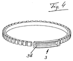
- the axial mobility of the two Parts related to each other is according to the invention by a fastener tape prevents which connects the lower part with the upper part.
- the fastener tape leaves in an unlocked position, however, a rotational movement of the upper part of the measuring capsule in Reference to the lower part of the measuring capsule during such a rotary movement in one Lock position of the fastener tape is prevented.
- plastic Another major advantage in the use of plastic is that good thermally conductive housing parts, such as brass, can be avoided, so that the Heat transfer from warm liquid to the outside or from external heat in cool liquid through the housing wall is significantly reduced.
- Semi-crystalline partially aromatic polyamide especially heat-stabilized and glass fiber reinforced polyphthalamide.
- the invention offers a particular advantage when used as a heat meter which a temperature sensor through the housing, namely the lower part of the measuring capsule and / or upper part, in particular introduced tangentially into an annular flow channel is so that the temperature sensor the temperature of the flowing Liquid measures. Due to the use of thermally well insulating plastic for the two housing parts are minimized measurement errors, so that a better one Measuring accuracy regardless of the outside temperature outside the meter is possible if the outside temperature is different from the temperature of the flowing Liquid deviates. This is particularly important in modern building technology the flow meter of this type is also used as a hot water consumption meter become.
- the liquid flow in the measuring capsule counter begins coaxially in the one-pipe connection part an annular space between the lower part of the measuring capsule and the measuring chamber.
- the impeller is located in a basket-like measuring chamber with radial oblique Inflow slots provided and in the floor area with the exception of the lower Bearing for the impeller is designed open.
- a bottom part is arranged leading away from the bottom of the measuring chamber for its part can be rotatably inserted into the lower part of the measuring capsule and the seals for carries the inner fluid flow.
- This bottom part directs the liquid to the inside Bore of the one-pipe connection part, with which it leaves the meter.
- Measuring chamber and Bottom part are coaxially rotatable, so that when twisting one Opening between the outer and inner water channels is constantly open or can be closed, thus achieving a bypass effect to the measuring chamber becomes.
- This adjustment movement is from the outside by turning the upper part of the measuring capsule causes.
- the upper part of the measuring capsule is positively connected to the measuring chamber part and carries the upper bearing for the impeller.
- the lower part of the measuring capsule should be at least partially annular in the upper part of the measuring capsule surround; the lower part here has an opening in the form of an elongated hole.
- the upper part of the measuring capsule has an im essential all-round groove-shaped recess for receiving the Fastening tape provided.
- the fastener tape should have a head piece that positively in the circumferentially extending opening in Lower part of the measuring capsule can be pressed in and clamped there or, for example, by means of a screw is screwable.
- the impeller has in particular one or more magnetic elements, which is linked to a measuring or counter, which is particularly above the measuring chamber in particular is located in the interior of a cover, which is covered with the measuring capsule and / or top part is connectable.
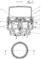
- a mechanical measuring capsule water meter is finally on Single pipe connection part (EAT) shown assembled.
- EAT Single pipe connection part
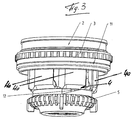
- Locking screw 14 is used to lock the fastener tape and the position of the Lower part 1 in relation to upper part 2 after adjustment on a test bench.
- the Lower part of measuring capsule 1 with the 2 inch thread serves as the base part for all other components of the counter.
- the actual measuring chamber is made according to Figure 2 from a bottom part 5, the Measuring chamber part 4 with the lower bearing 6 of the impeller 8 and the Measuring capsule upper part 2 is formed.
- the measuring chamber part 4 and the bottom part 5 provide one kind of "basket” since the measuring chamber part has 4 inclined inflow slots, which connecting channels create from the measuring chamber into the flow channel SK, which of the measuring chamber part 4 and the bottom part 5 on the one hand and the Measuring capsule lower part 1, on the other hand, is limited radially on the inside and radially on the outside. That too Measuring water flows coaxially via inlet E into this flow channel SK and out of the measuring chamber via the annular outlet channel A in the base part 5 again out.
- the flowing liquid drives the impeller 8, which with the upper bearing pin 6 in Measuring capsule upper part 2 is mounted.
- the rotary movement of the impeller 7 with the Bearing bush 8 is on the magnetic element 9 on the upper end of the Bearing bush 8 to a magnetic element in a not shown mechanical counter, which is particularly transparent Cover capsule or cover 10 is housed.
- the upper measuring capsule 2 has a magnetic shield ring 15.
- the cover 10 is on the upper part 2 attached.
- the bottom part 5 When installing the meter, the bottom part 5 is first inserted into the lower part of the measuring capsule 1 used; it sits axially and is held in place by several bars. Then the measuring chamber part 4 is placed on the bottom part 5, so that a Rotational movement possible relative to each other and therefore the passage cross section of the Bypass opening 12 between the upper flange of the bottom part 5 and the lower Flange of the measuring chamber part 4 is released more or less.
- the top 2 is used with the seal O-ring 11 in the lower part 1 that its Geometry on the underside in a form-fitting manner in the opposite side of the measuring chamber part 4 intervenes.
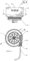
- the measuring capsule upper part 2 has a radial bore which is half according to FIG open bypass corresponds and can be rotated to both sides.
- the locking screw 14 is screwed so that the lower part 1 is no longer rotatable in relation to the upper part 2.
- the cross-section of the bypass is locked.
Landscapes
- Physics & Mathematics (AREA)
- Fluid Mechanics (AREA)
- General Physics & Mathematics (AREA)
- Measuring Volume Flow (AREA)
Applications Claiming Priority (2)
| Application Number | Priority Date | Filing Date | Title |
|---|---|---|---|
| DE10031782 | 2000-07-04 | ||
| DE2000131782 DE10031782A1 (de) | 2000-07-04 | 2000-07-04 | Flüssigkeitsströmungszähler, wie Wasserzähler, und Wärmezähler |
Publications (2)
| Publication Number | Publication Date |
|---|---|
| EP1170575A2 true EP1170575A2 (fr) | 2002-01-09 |
| EP1170575A3 EP1170575A3 (fr) | 2003-01-02 |
Family
ID=7647274
Family Applications (1)
| Application Number | Title | Priority Date | Filing Date |
|---|---|---|---|
| EP01109719A Withdrawn EP1170575A3 (fr) | 2000-07-04 | 2001-04-20 | Débitmètre pour liquide,comme compteur de l' eau,et compteur de chaleur |
Country Status (3)
| Country | Link |
|---|---|
| EP (1) | EP1170575A3 (fr) |
| DE (1) | DE10031782A1 (fr) |
| PL (1) | PL348141A1 (fr) |
Cited By (2)
| Publication number | Priority date | Publication date | Assignee | Title |
|---|---|---|---|---|
| DE102006045325A1 (de) * | 2006-09-22 | 2008-04-03 | Hydrometer Gmbh | Zählergehäuse |
| CN103900738A (zh) * | 2014-01-18 | 2014-07-02 | 宁波百立康智能仪表有限公司 | 一种适用于双时间测量法检测的热量表 |
Families Citing this family (3)
| Publication number | Priority date | Publication date | Assignee | Title |
|---|---|---|---|---|
| DE102004012414C5 (de) * | 2004-03-13 | 2010-12-16 | Hydrometer Gmbh | Messeinsatz und Fluidzähler |
| DE102007017461B4 (de) | 2007-04-10 | 2014-04-17 | Micropelt Gmbh | Vorrichtung mit einer elektrischen Einrichtung und einem Modul zur Energieversorgung der elektrischen Einrichtung |
| DE102010033683B4 (de) * | 2010-08-06 | 2013-01-03 | Hans-Holger Körner | Messkapsel für Wärmezähler |
Family Cites Families (8)
| Publication number | Priority date | Publication date | Assignee | Title |
|---|---|---|---|---|
| DE1573049B2 (de) * | 1966-03-05 | 1971-04-29 | Pollux GmbH, Wassermesser u Arma turenfabnk, 6700 Ludwigshafen | Fluessigkeitszaehler mit kunststoffauskleidung |
| DE2337465C2 (de) * | 1973-07-24 | 1987-05-07 | E. Wehrle Gmbh, 7743 Furtwangen | Flüssigkeitszähler |
| DE2400408A1 (de) * | 1974-01-05 | 1975-07-10 | Herbert Hess | Kunststoff-gehaeuse |
| US4663970A (en) * | 1985-09-03 | 1987-05-12 | Rockwell International Corporation | Tamperproof water meter |
| DE4005860C1 (en) * | 1990-02-21 | 1991-05-29 | Berliner Wasser-Betriebe Eigenbetrieb Von Berlin, 1000 Berlin, De | Water meter internal cladding - comprises thixotropic mixt. of epichlorohydrin based epoxy! resin and bisphenol=A or -F, with poly:amine liq. |
| US5365785A (en) * | 1992-06-17 | 1994-11-22 | Grinnell Corporation | Submersible meter register case and assembly |
| US5339686A (en) * | 1993-02-03 | 1994-08-23 | Badger Meter, Inc. | Water meter housing connection apparatus |
| DE19616658B4 (de) * | 1996-03-18 | 2009-11-19 | Ifm Electronic Gmbh | Meßgerät, z. B. Druckmeßgerät oder Strömungsmeßgerät |
-
2000
- 2000-07-04 DE DE2000131782 patent/DE10031782A1/de not_active Withdrawn
-
2001
- 2001-04-20 EP EP01109719A patent/EP1170575A3/fr not_active Withdrawn
- 2001-06-19 PL PL34814101A patent/PL348141A1/xx unknown
Cited By (3)
| Publication number | Priority date | Publication date | Assignee | Title |
|---|---|---|---|---|
| DE102006045325A1 (de) * | 2006-09-22 | 2008-04-03 | Hydrometer Gmbh | Zählergehäuse |
| DE102006045325B4 (de) * | 2006-09-22 | 2008-09-04 | Hydrometer Gmbh | Zählergehäuse |
| CN103900738A (zh) * | 2014-01-18 | 2014-07-02 | 宁波百立康智能仪表有限公司 | 一种适用于双时间测量法检测的热量表 |
Also Published As
| Publication number | Publication date |
|---|---|
| PL348141A1 (en) | 2002-01-14 |
| EP1170575A3 (fr) | 2003-01-02 |
| DE10031782A1 (de) | 2002-01-17 |
Similar Documents
| Publication | Publication Date | Title |
|---|---|---|
| DE3012059C2 (fr) | ||
| DE3509718C2 (de) | Verteilerventil mit Durchflußmesser | |
| CH690925A5 (de) | Verteilerventil mit Durchflussmesser. | |
| DE3733862A1 (de) | Stroemungsanzeige- bzw. -messgeraet | |
| DE3328782A1 (de) | Sanitaerarmatur sowie vorrichtung zur messung und anzeige eines oder mehrerer physikalischer parameter des den auslauf einer sanitaerarmatur durchstroemenden wassers | |
| DE68903963T2 (de) | Ventile. | |
| EP2226697A1 (fr) | Régulateur de débit | |
| DE69623637T2 (de) | Eine kugelventilkartusche für ein mischventil | |
| DE2337465C2 (de) | Flüssigkeitszähler | |
| EP0745798A2 (fr) | Poignée pour robinet sanitaire | |
| EP1170575A2 (fr) | Débitmètre pour liquide,comme compteur de l' eau,et compteur de chaleur | |
| EP0884514B1 (fr) | Débitmètre | |
| EP0341345A1 (fr) | Vanne avec filtre intégré | |
| EP0270960B1 (fr) | Appareil de surveillance d'écoulement | |
| DE2255278A1 (de) | Wasserhahn mit schieber | |
| DE69100395T2 (de) | Ventil. | |
| DE3344680C2 (de) | Türschließer | |
| EP0943901A1 (fr) | Raccord pour un dispositif de mesure de débit d'un liquide | |
| EP0329800B1 (fr) | Partie supérieure de vanne | |
| EP1505372A1 (fr) | Garniture de mesure et de réglage du débit d'un fluide hydraulique dans un tube | |
| EP1898134A2 (fr) | Dispositif de restriction pour installations de chauffage et de refroidissement | |
| DE2410260A1 (de) | Regelvorrichtung fuer stroemende medien | |
| EP0447811A1 (fr) | Dispositif d'affichage et de la mesure de débit | |
| DE202007012540U1 (de) | Handantrieb für Ventile | |
| WO2012126518A1 (fr) | Appareil pour mesurer un courant d'eau |
Legal Events
| Date | Code | Title | Description |
|---|---|---|---|
| PUAI | Public reference made under article 153(3) epc to a published international application that has entered the european phase |
Free format text: ORIGINAL CODE: 0009012 |
|
| AK | Designated contracting states |
Kind code of ref document: A2 Designated state(s): AT BE CH CY DE DK ES FI FR GB GR IE IT LI LU MC NL PT SE TR |
|
| AX | Request for extension of the european patent |
Free format text: AL;LT;LV;MK;RO;SI |
|
| PUAL | Search report despatched |
Free format text: ORIGINAL CODE: 0009013 |
|
| AK | Designated contracting states |
Kind code of ref document: A3 Designated state(s): AT BE CH CY DE DK ES FI FR GB GR IE IT LI LU MC NL PT SE TR |
|
| AX | Request for extension of the european patent |
Free format text: AL;LT;LV;MK;RO;SI |
|
| RIC1 | Information provided on ipc code assigned before grant |
Free format text: 7G 01F 1/10 A, 7G 01F 1/115 B, 7G 01F 15/18 B, 7G 01F 15/14 B |
|
| AKX | Designation fees paid | ||
| REG | Reference to a national code |
Ref country code: DE Ref legal event code: 8566 |
|
| STAA | Information on the status of an ep patent application or granted ep patent |
Free format text: STATUS: THE APPLICATION IS DEEMED TO BE WITHDRAWN |
|
| 18D | Application deemed to be withdrawn |
Effective date: 20030703 |