EP1172149B1 - Fliessbett-Gegenstrahlmühle - Google Patents
Fliessbett-Gegenstrahlmühle Download PDFInfo
- Publication number
- EP1172149B1 EP1172149B1 EP01114088A EP01114088A EP1172149B1 EP 1172149 B1 EP1172149 B1 EP 1172149B1 EP 01114088 A EP01114088 A EP 01114088A EP 01114088 A EP01114088 A EP 01114088A EP 1172149 B1 EP1172149 B1 EP 1172149B1
- Authority
- EP
- European Patent Office
- Prior art keywords
- milling
- fluidised bed
- jet mill
- milling container
- counter jet
- Prior art date
- Legal status (The legal status is an assumption and is not a legal conclusion. Google has not performed a legal analysis and makes no representation as to the accuracy of the status listed.)
- Expired - Lifetime
Links
- 239000000463 material Substances 0.000 claims abstract description 32
- 238000004140 cleaning Methods 0.000 claims description 8
- 230000005484 gravity Effects 0.000 claims description 4
- 238000003801 milling Methods 0.000 claims 19
- 238000007599 discharging Methods 0.000 claims 1
- 239000002131 composite material Substances 0.000 abstract 2
- 238000003860 storage Methods 0.000 description 9
- 230000007704 transition Effects 0.000 description 5
- 239000002245 particle Substances 0.000 description 3
- 238000010923 batch production Methods 0.000 description 1
- 238000011109 contamination Methods 0.000 description 1
- 230000001419 dependent effect Effects 0.000 description 1
- 238000009826 distribution Methods 0.000 description 1
- 230000003670 easy-to-clean Effects 0.000 description 1
- 230000002349 favourable effect Effects 0.000 description 1
- 239000012530 fluid Substances 0.000 description 1
- 238000005243 fluidization Methods 0.000 description 1
- 238000004519 manufacturing process Methods 0.000 description 1
- 238000000034 method Methods 0.000 description 1
- 239000000825 pharmaceutical preparation Substances 0.000 description 1
- 229940127557 pharmaceutical product Drugs 0.000 description 1
- 238000007789 sealing Methods 0.000 description 1
- 238000000926 separation method Methods 0.000 description 1
- 238000003466 welding Methods 0.000 description 1
Images


Classifications
-
- B—PERFORMING OPERATIONS; TRANSPORTING
- B02—CRUSHING, PULVERISING, OR DISINTEGRATING; PREPARATORY TREATMENT OF GRAIN FOR MILLING
- B02C—CRUSHING, PULVERISING, OR DISINTEGRATING IN GENERAL; MILLING GRAIN
- B02C23/00—Auxiliary methods or auxiliary devices or accessories specially adapted for crushing or disintegrating not provided for in preceding groups or not specially adapted to apparatus covered by a single preceding group
- B02C23/08—Separating or sorting of material, associated with crushing or disintegrating
- B02C23/16—Separating or sorting of material, associated with crushing or disintegrating with separator defining termination of crushing or disintegrating zone, e.g. screen denying egress of oversize material
-
- B—PERFORMING OPERATIONS; TRANSPORTING
- B02—CRUSHING, PULVERISING, OR DISINTEGRATING; PREPARATORY TREATMENT OF GRAIN FOR MILLING
- B02C—CRUSHING, PULVERISING, OR DISINTEGRATING IN GENERAL; MILLING GRAIN
- B02C19/00—Other disintegrating devices or methods
- B02C19/06—Jet mills
- B02C19/068—Jet mills of the fluidised-bed type
Definitions
- the invention relates to fluidized bed counter-jet mills which are designed as classifier mills and relates to the design and arrangement of the components.
- Fluid bed counter-jet mills generally consist of a vertical axis cylindrical grinding container, wherein jet nozzles are provided in the lower part of the grinding container. The jet nozzles are directed against each other so that the grinding material in the grinding container is sucked into the jets and accelerated with them, wherein it is crushed due to mutual collisions between the Mahlgutteilchen by impact.
- a viewing device is present in the upper part of the grinding container.
- the sighting device is generally designed as a centrifugal separator, whereby particles finer than the cut-off grain size are transported inwardly into the rotating blade wheel of the classifier and separated, whereas particles which are coarser than the cut-off particle size are thrown off the rotating blade wheel and in the grinding container remain.
- Such a classifier mill is eg off DE 33 38 138 C2 known. It is designed as a fluidized-bed jet mill, with a free from the internals to guide the grinding gas jets grinding chamber, in the bottom region of a nozzle with vertically upwardly exiting, both for grinding and fluidization of the material located in the grinding chamber serving gas jet is arranged and the filled up to such a height completely with the material to be comminuted, that good and gas emerge as a low-speed fountain from the bed of material, this fountain for supplying a provided above the surface of the bed of material, operated independently of the momentum of emerging from the floor nozzle jet reformers serves.
- the local sighting device is arranged in the upper part of the grinding container and rotates about a vertical axis.
- the separator wheel operates on the principle of centrifugal force and separates sufficiently finely ground material from the material to be ground and guides it out of the grinding container via a fine material discharge located above the separator wheel. Furthermore, an arranged above the fine material discharge storage and drive device for the rotating reformerrad available.
- the object of the invention is therefore to improve a fluidized bed rotary jet mill with viewing device such that it is easily accessible, can be completely cleaned easily and easily.
- the fluidized bed counter-jet mill provides a reformerradan angel, which forms a structural unit together with the storage and drive device and is detachably connected to the grinding container.
- the unit is movable by kinematic means relative to the grinding container so that the classifier wheel can be removed through the fines discharge upwards out of the grinding container.
- the fines discharge remains connected to the grinding container.
- the grinding container is thus not divided and made accessible in a plane between the lower part in which the grinding chamber is located and the upper part in which the viewing device is located, but the parting plane is located within the region of the viewing device.
- both the classifier wheel and the interior of the fine-material discharge space and the classifier wheel shaft are freely accessible.
- the classifier wheel can be pivoted through 180 °, so that the classifier wheel and the grinding container are optimally accessible and can be easily cleaned.
- the pivotability is achieved by a kinematics, which first moves the crusherrad together with the storage and drive device vertically upwards and then rotated by an angle greater than 90 °, preferably up to 180 ° about an axis in a horizontal plane.
- the axis of rotation passes through the center of gravity of the assembly of sorterrad, storage and drive device.
- This opening principle can be advantageous not only in fluidized bed jet mills, but e.g. can also be used in impact mills with a rotating beater.
- the crusherrad is functionally replaced by a rotating Schlägerwerk and the container wall carries at the height of the beater mechanism over the circumference of the housing, the inner impact ribs or grinding tracks.
- Mahlguteinlauf The arranged above the rotating Schlägerwerk space with line connection serves as Mahlguteinlauf.
- the Mahl Kunststoffringtechnische for distribution of the grinding air is arranged on the terminals of the individual jet nozzles above the jet nozzles, preferably at the level of reformerrades. This arrangement avoids contamination of the Mahl Kunststoffringtechnisch with product dusts.
- Mahl Kunststofftechnisch are arranged at the same height to the jet nozzles or below, so that it has come because of backflow in the lines for sucking ground material in the Mahl Kunststoffringtechnisch.
- the connecting pieces of the flexible hose lines are arranged on the Mahl Kunststoffringtechnisch offset from the connecting pieces to the nozzles.
- the staggered arrangement is such that when Loosen the fittings on the nozzles, align the hoses by gravity into a vertical position while pivoting the loosened fittings laterally away from the nozzles. As a result, the nozzle and the nozzle holding the grinding container for cleaning purposes is easily accessible.
- the corner weld in the transition region of the cylindrical grinding container wall and the conical bottom is replaced by a respective flat weld on the vertical grinding container wall and on the conical wall of the bottom.
- an annular stop plate between Mahl alternerwand and the bottom is welded, which has on its inner annular surface a transition contour with a large radius at which no material can attach and which is easy to clean.
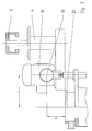
- FIG. 1 shows the fine material discharge space 1, to which the fine material outlet 2 is connected in a spatial position between separator wheel 3 and separator wheel storage 4.
- the prepareerrad 3 forms together with the prepareerradlagerung 4 and the drive 14 a structural unit, which is releasably connected by means of a bearing flange 5 via screws 8 with the mill 15.
- the bearing flange 5 forms a tight conclusion for the fines discharge space 1.
- the bearing flange 5 is centered over a fit 6 relative to the mill housing 7.
- the Mahlluftring horrides 16 is mounted externally on the mill housing 7 at the level of treaterrades 3. Over the circumference of the Mahlluftring effet 16 a plurality of connecting pieces 17 are arranged, to which elastic pressure hoses 9 are connected. The pressure hoses 9 lead the supplied via the Mahl Kunststoffring effet 16 via the terminal 21 compressed air to each jet nozzle 12. The pressure hoses 9 are detachably connected via additional connecting pieces 10 with the jet nozzles 12. The upper connecting pieces 17 are offset on the circumference relative to the lower connecting pieces 10, so that when loosening the screw 13 at the connecting pieces 10, the pressure hoses 9 pivot in a vertical position due to gravity and release the inlet openings to the jet nozzles 12 (see also Fig. 5).
- Fig. 2 the assembly of bearing flange 5, as well as storage 4 - and drive means 14 can be seen in the closed state.
- the belt drive 18 connects the drive device 14 with the bearing 4 and translates the rotational speed of the drive device 14 to a suitable speed for the separator wheel.
- the pivoting device shown in Fig. 3 allows rotation of the assembly of preparerrad 3, and storage 4 - and drive means 14 about the axis of rotation 19 by 180 °.
- the axis of rotation of the crushererrades 3 is then aligned vertically and the preparerrad 3 is accessible in an upwardly open position.
- the distance L and H of the axis of rotation 19 from the center of the cleaning opening 20 is selected so that the cleaning opening 20 is completely exposed and the interior is easily accessible.
- the opening operation of Fig. 4 is controlled so that the rotary drive and the vertical drive of the pivoting device can be moved simultaneously.
- the axis of rotation of the pivoting device is preferably in or as close as possible to the center of mass.
- a stop plate 23 is provided in the transition from the cylindrical grinding container wall of the mill 15 and the conical grinding container bottom 22, which has a transition rounding 24 at the inner radial edge.
- stopper plate 23 extending around the mill 15 are provided on the top and bottom of the stop plate, which reduce the stop plate 23 to the required wall thickness of Mahl alternerwand.
- the opening principle according to the invention can also be applied to mills with a beater mechanism, which however are not part of the present invention.
- the rotating working part 26 is equipped with impact beaters 27, which cooperates with a mounted on the inner circumference of the grinding containers Mahlbahn 28.
- Mahlgutholzgabe takes place via the inlet 29 into the feed space 30, from where the ground material is distributed to the impact beaters 27.
Landscapes
- Engineering & Computer Science (AREA)
- Food Science & Technology (AREA)
- Disintegrating Or Milling (AREA)
- Combined Means For Separation Of Solids (AREA)
- Crushing And Grinding (AREA)
- Paper (AREA)
- Finish Polishing, Edge Sharpening, And Grinding By Specific Grinding Devices (AREA)
Description
- Die Erfindung bezieht sich auf Fließbett-Gegenstrahlmühlen, die als Sichtermühlen ausgebildet sind und betrifft die Gestaltung und Anordnung der Komponenten.
- Fließbett-Gegenstrahlmühlen bestehen im allgemeinen aus einem vertikalachsigen zylindrischen Mahlbehälter, wobei im unteren Teil des Mahlbehälter Strahldüsen vorgesehen sind. Die Strahldüsen sind derart gegeneinander gerichtet, daß das im Mahlbehälter befindliche Mahlgut in die Strahlen eingesaugt und mit diesen beschleunigt wird, wobei es aufgrund gegenseitiger Kollisionen zwischen den Mahlgutteilchen durch Prall zerkleinert wird.
- Um fertig gemahlenes Feingut aus der Mühle zu entfernen, wobei noch nicht ausreichend gemahlenes Gut in der Mühle verbleiben soll, ist im oberen Teil des Mahlbehälters eine Sichtvorrichtung vorhanden. Die Sichtvorrichtung ist im allgemeinen als Zentrifugalkraft-Sichter ausgebildet, wobei Teilchen, die feiner als die Trennkorngröße sind, nach innen in das rotierende Schaufelrad des Sichters transportiert und abtrennt werden, hingegen Teilchen die gröber sind als die Trennkorngröße vom rotierenden Schaufelrad abgeschleudert werden und im Mahlbehälter verbleiben.
- Eine derartige Sichtermühle ist z.B. aus
DE 33 38 138 C2 bekannt. Sie ist als Fließbettstrahlmühle ausgebildet, mit einer von Einbauten zur Führung der der Mahlung dienenden Gastrahlen freien Mahlkammer, in deren Bodenbereich eine Düse mit senkrecht nach oben austretendem, sowohl zur Mahlung als auch zur Fluidisierung des in der Mahlkammer befindlichen Gutes dienendem Gasstrahl angeordnet ist und die bis zu einer solchen Höhe vollständig mit dem zu zerkleinerndem Gut gefüllt ist, daß Gut und Gas als Fontäne geringer Geschwindigkeit aus dem Gutbett austreten, wobei diese Fontäne zur Speisung eines oberhalb der Oberfläche des Gutbettes vorgesehenen, unabhängig vom Impuls des aus der Bodendüse austretenden Strahls betriebenen Sichters dient. - Es sind dabei eine bestimmte Anzahl weiterer, unterhalb der Oberfläche des Gutbettes angeordnete und in diese mündende Strahldüsen vorgesehen, deren Mündungen in einer senkrecht zur Achse der Bodendüse verlaufenden Ebene auf einem zur Achse der Bodendüse koaxialen Kreis gleichmäßig verteilt liegen, und deren Achsen sich in einem Punkt auf der Achse der Bodendüse unterhalb der Ebene der Düsenmündungen schneiden.
- Die dortige Sichtvorrichtung ist im oberen Teil des Mahlbehälters angeordnet und rotiert um eine vertikale Achse. Das Sichterrad arbeitet nach dem Zentrifugalkraft-Prinzip und trennt ausreichend fein gemahlenes Gut vom Mahlgut und führt es über einen oberhalb des Sichterrades angeordneten Feingutaustrag aus dem Mahlbehälter heraus. Weiterhin ist eine oberhalb des Feingutaustrages angeordnete Lagerungs- und Antriebseinrichtung für das rotierende Sichterrad vorhanden.
- Bei den bis heute bekannten Fließbett-Gegenstrahlmühlen ist der gesamte Aufbau des Mahlbehälters und die Anordung der zugehörigen Komponenten nach rein verfahrenstechnischen Gesichtspunkten ausgelegt. Es besteht jedoch immer mehr Bedarf an verfahrenstechnischen Maschinen, die durch den Anwender leicht montiert und demontiert werden können und für eine gründliche Reinigung leicht zugänglich sein müssen.
- Besonders in der pharmazeutischen Industrie und bei der Tonerherstellung muß von einem Chargenbetrieb ausgegangen werden, wobei nur kleine Mengen von Produkt gemahlen werden und kurz darauf völlig andere Produkte in der selben Mühle verarbeitet werden sollen.
- So ist es z.B. beim Wechsel zu einem andersfarbigen Tonerprodukt, oder beim Wechsel pharmazeutischer Produkte unterschiedlicher Wirksamkeit zwingend erforderlich die gesamte Maschine gründlich zu reinigen, damit keine Restmengen des vorangegangen Produktes das anschließend zu mahlende Produkt kontaminiert.
- Die Reinigung der bisherigen Sichtermühlen ist umständlich und zeitaufwendig, insbesondere besteht ein hohes Risiko, daß noch geringe Mengen von Produkt auch nach der Reinigung in der Maschine verbleiben.
- Aufgabe der Erfindung ist es deshalb, eine Fließbett-Gegestrahlmühle mit Sichteinrichtung derart zu verbessern, daß sie leicht zugänglich ist, einfach und ohne großen Aufwand vollständig gereinigt werden kann.
- Diese Aufgabe wird durch die Merkmale des Anspruchs 1 gelöst. Weitere zusätzliche und vorteilhafte Ausgestaltungen sind den Unteransprüchen zu entnehmen.
- Die erfindungsgemäße Fließbett-Gegenstrahlmühle sieht eine Sichterradanordnung vor, die zusammen mit der Lagerungs- und Antriebseinrichtung eine Baueinheit bildet und mit dem Mahlbehälter lösbar verbunden ist. Dabei ist die Baueinheit durch kinematische Einrichtungen gegenüber dem Mahlbehälter derart beweglich, daß das Sichterrad durch den Feingutaustrag hindurch nach oben aus dem Mahlbehälter entfernt werden kann. Der Feingutaustrag bleibt weiterhin mit dem Mahlbehälter verbunden.
- Der Mahlbehälter wird also nicht in einer Ebene zwischen dem unteren Teil in dem sich der Mahlraum befindet und dem oberen Teil in dem sich die Sichtvorrichtung befindet geteilt und zugänglich gemacht, sondern die Trennebene befindet sich innerhalb des Bereichs der Sichtvorrichtung. Dies hat den Vorteil, daß nicht nur der Mahlraum gänzlich zugänglich wird, sondern auch die Sichtvorrichtung sowohl von außen als auch von innen zugänglich wird.
- Durch die erfindungsgemäße Trennung der Sichtvorrichtung von dem Mahlbehälter wird sowohl das Sichterrad als auch das Innere des Feingutaustragsraums und die Sichterradwelle frei zugänglich.
- Da der Feingutaustragsraum und die Feingutleitung weiterhin mit dem Mahlbehälter verbunden bleiben, müssen keine Versorgungsleitungen abgetrennt werden um den Mahlbehälter öffen zu können und zugänglich zu machen.
- In einer bevorzugten Ausgestaltung kann das Sichterrad um 180° verschwenkt werden, so daß das Sichterrad und auch der Mahlbehälter optimal zugänglich werden und leicht gereinigt werden können.
- Die Schwenkbarkeit wird erreicht durch eine Kinematik, die das Sichterrad zusammen mit der Lagerungs- und Antriebseinrichtung zunächst vertikal nach oben verschiebt und anschließend um einen Winkel größer als 90°, vorzugsweise bis 180° um eine Achse in horizontaler Ebene dreht. Im Idealfall verläuft die Drehachse durch den Massenschwerpunkt der Baueinheit von Sichterrad, Lagerungs- und Antriebseinrichtung.
- Dieses Öffnungsprinzip kann nicht nur bei Fließbett-Gegestrahlmühlen vorteilhaft sein, sondern z.B. auch bei Prallmühlen mit einem rotierenden Schlägerwerk eingesetzt werden. Dabei ist funktional das Sichterrad durch ein rotierendes Schlägerwerk ersetzt und die Behälterwand trägt in Höhe des Schlägerwerks über den Umfang des Gehäuses die innenliegende Prallrippen oder Mahlbahnen. Der oberhalb des rotierenden Schlägerwerks angeordnete Raum mit Leitungsanschluß dient als Mahlguteinlauf.
- In einer weiteren Ausführungsvariante der Erfindung ist die Mahlluftringleitung zur Verteilung der Mahlluft auf die Anschlüsse der einzelnen Strahldüsen oberhalb der Strahldüsen, vorzugsweise in Höhe des Sichterrades angeordnet. Diese Anordnung vermeidet eine Verschmutzung der Mahlluftringleitung mit Produktstäuben. Bei den bisherigen Strahlmühlen sind Mahlluftleitung in gleicher Höhe zu den Strahldüsen oder unterhalb angeordnet, so daß es aufgrund von Rückströmungen in den Leitungen zum Einsaugen von Mahlgut in die Mahlluftringleitung gekommen ist. Um einen leichten Zugang zu den Düsen zu ermöglichen sind erfindungsgemäß die Anschlußstücke der flexiblen Schlauchleitungen an der Mahlluftringleitung gegenüber den Anschlußstücken an den Düsen versetzt angeordnet. Die versetzte Anordnung erfolgt derart, daß beim Lösen der Anschlußstücke an den Düsen, sich die Schläuche aufgrund der Schwerkraft in eine vertikale Lage ausrichten und dabei die gelösten Anschlußstücke von den Düsen seitlich wegschwenken. Dadurch wird die Düse und die Düsenhaltung am Mahlbehälter zu Reinigungszwecken leicht zugänglich.
- Für eine leichte Reinigung der Innenflächen des Mahlbehälters sind die Anzahl der Trennebenen minimiert. Die erforderlichen Schweißnähte sind in Positionen verlegt, die weniger Ansatzmöglichkeiten für Produkt bieten und somit ebenfalls leichter zu reinigen sind. So ist erfindungsgemäß die Eckschweißnaht im Übergangsbereich von zylindrischer Mahlbehälterwand und konischem Boden durch je eine ebene Schweißnaht an der senkrechten Mahlbehälterwand und an der konischen Wand des Bodens ersetzt. Dazu wird eine ringförmige Anschlagplatte zwischen Mahlbehälterwand und Boden geschweißt, die an ihrer inneren Ringfläche eine Übergangskontur mit großem Radius aufweist, an der sich kein Material ansetzten kann und die leicht zu reinigen ist.
-
- Fig.1 zeigt einen Querschnitt der erfindungsgemäßen Fließbett-Gegenstrahlmühle.
- Fig.2 zeigt die Baueinheit von Sichterrad, sowie Lagerungs- und Antriebseinrichtung im geschlossenen Zustand.
- Fig.3 zeigt die Baueinheit von Sichterrad, sowie Lagerungs- und Antriebseinrichtung im geöffneten Zustand in der 180° Position.
- Fig.4 zeigt eine Öffnungssequenz der erfindungsgemäßen Kinematik.
- Fig.5 zeigt eine Ansicht der versetzt angeordneten Mahlluftanschlüsse.
- Fig.6 zeigt die erfindungsgemäße Anschlagplatte.
- Fig.7 zeigt das erfindungsgemäße Öffnungsprinzip an einer Prallmühle.
- Fig.1 zeigt den Feingutaustragsraum 1, an den der Feingutaustritt 2 in einer räumlichen Lage zwischen Sichterrad 3 und Sichterradlagerung 4 angeschlossen ist. Das Sichterrad 3 bildet zusammen mit der Sichterradlagerung 4 und dem Antrieb 14 eine Baueinheit, die mit Hilfe eines Lagerflansches 5 über Schrauben 8 mit der Mühle 15 lösbar verbunden ist. Der Lagerflansch 5 bildet dabei einen dichten Abschluß für den Feingutaustragsraum 1. Der Lagerflansch 5 wird über eine Passung 6 gegenüber dem Mühlengehäuse 7 zentriert.
- Die Mahlluftringleitung 16 ist außen am Mühlengehäuse 7 in Höhe des Sichterrades 3 angebracht. Über den Umfang der Mahlluftringleitung 16 sind mehrere Anschlußstücke 17 angeordnet, an denen elastische Druckschläuche 9 angeschlossen sind. Die Druckschläuche 9 leiten die über die Mahlluftringleitung 16 über den Anschluß 21 zugeführte Druckluft zu jeder einzelnen Strahldüse 12. Die Druckschläuche 9 sind über zusätzliche Anschlußstücke 10 mit den Strahldüsen 12 lösbar verbunden. Die oberen Anschlußstücke 17 sind am Umfang gegenüber den unteren Anschlußstücken 10 versetzt angeordnet, so daß bei Lösen der Verschraubung 13 an den Anschlußstücken 10 die Druckschläuche 9 aufgrund der Schwerkraft in eine senkrechte Lage schwenken und die Eintrittsöffnungen zu den Strahldüsen 12 freigeben (siehe auch Fig.5).
- In Fig. 2 ist die die Baueinheit von Lagerflansch 5, sowie Lagerungs 4 - und Antriebseinrichtung 14 im geschlossenen Zustand zu sehen. Der Riementrieb 18 verbindet die Antriebseinrichtung 14 mit der Lagerung 4 und übersetzt die Drehzahl der Antriebseinrichtung 14 auf eine geeignete Drehzahl für das Sichterrad.
- Die in Fig. 3 gezeigte Schwenkeinrichtung ermöglicht eine Drehung der Baueinheit von Sichterrad 3, sowie Lagerungs 4 - und Antriebseinrichtung 14 um die Drehachse 19 um 180°. Die Drehachse des Sichterrades 3 ist dann vertikal ausgerichtet und das Sichterrad 3 ist in einer nach oben offenen Position zugänglich. Der Abstand L und H der Drehachs 19 von der Mitte der Reingungsöffnung 20 ist so gewählt, daß die Reinigungsöffnung 20 vollständig frei liegt und der Innenraum gut zugänglich ist.
- Der Öffnungsvorgang nach Fig. 4 ist so gesteuert, daß der Drehantrieb und der Vertikalantrieb der Schwenkeinrichtung gleichzeitig bewegt werden können. Die Drehachse der Schwenkeinrichtung liegt bevorzugt im bzw. möglichst nahe am Massenschwerpunkt.
- In Fig.6 ist im Übergang von zylindrischer Mahlbehälterwand der Mühle 15 und dem konischen Mahlbehälterboden 22 eine Anschlagplatte 23 vorgesehen, die eine Übergangsrundung 24 am inneren radialen Rand aufweist. Zur Erzielung eines schweißtechnisch günstigen Übergangs von Mahlbehälterwand zum konischen Mahlbehälterboden 22 sind auf der Ober- und Unterseite der Anschlagplatte 23 ringförmig um die Mühle 15 verlaufende Freistiche 25 angebracht, die die Anschlagplatte 23 auf die erforderliche Wandstärke der Mahlbehälterwand reduzieren.
- Das erfindungsgemäße Öffnungsprinzip kann gemäß Fig. 7 auch bei Mühlen mit Schlägerwerk Anwendung findern, welche jedoch nicht Teil der vorliegenden Erfindung sind. Dazu ist das rotierende Arbeitsteil 26 mit Prallschlägern 27 bestückt, die mit einer am inneren Umfang des Mahlbehältern angebrachten Mahlbahn 28 zusammenwirkt. Die Mahlgutaufgabe erfolgt dabei über den Zulauf 29 in den Aufgaberaum 30, von wo aus das Mahlgut auf die Prallschläger 27 verteilt wird.Die Abdichtung 31 der Arbeitsräume erfolgt zwischen dem Aufgaberaum 30 und dem Mahlraum 32.
Claims (9)
- Fließbett-Gegenstrahlmühle, bestehend aus:- einem Mahlbehälter zur Aufnahme von Mahlgut- einer Anzahl nach innen gerichteter Gegenstrahldüsen (12), die im unteren Teil des Mahlbehälters angeordnet und derart ausgerichtet sind, daß sich die Strahlen in einem gemeinsamen Punkt treffen, zur Mahlung und Fluidisierung des im Mahlbehälter befindlichen Mahlgutes- einer im oberen Teil des Mahlbehälters angeordneten Sichtvorrichtung mit einem um eine vertikale Achse rotierenden, nach dem Zentrifugalkraft-Prinzip arbeitenden Sichterrad (3), zur Abtrennung von ausreichend fein gemahlenem Gut vom Mahlgut- einer Lagerungs- und Antriebseinrichtung (4, 14) für das rotierende Sichterrad (3)- einer Gutaufgabe zur Zuführung von Mahlgut in den Mahlbehälters- einem oberhalb des Sichterrades (3) angeordneten Feingutaustrag (1, 2), zum Abführen des abgetrennten, ausreichend fein gemahlenen Gutes aus dem Mahlbehälter dadurch gekennzeichnet, daß das Sichterrad (3) zusammen mit der Lagerungs- und Antriebseinrichtung (4, 14) eine Baueinheit bildet, die mit dem Mahlbehälter lösbar verbunden ist, wobei die Baueinheit durch kinematische Einrichtungen gegenüber dem Mahlbehälter derart beweglich ist, daß das Sichterrad (3) durch den Feingutaustrag (1, 2) hindurch nach oben aus dem Mahlbehälter entfernt werden kann, wobei der Feingutaustrag (1, 2) weiterhin mit dem Mahlbehälter verbunden bleibt.
- Fließbett-Gegenstrahlmühle nach Anspruch 1, dadurch gekennzeichnet, daß die Baueinheit von Lagerungs- und Antriebseinrichtung durch eine Hubeinrichtung linear in vertikaler Richtung verschiebbar und durch eine Dreheinrichtung um eine in der vertikalen Ebene liegende Achse schwenkbar ist.
- Fließbett-Gegenstrahlmühle nach Anspruch 2, dadurch gekennzeichnet, daß die Hubeinrichtung ein Hydraulikzylinder und die Dreheinrichtung ein Hydraulikmotor ist.
- Fließbett-Gegenstrahlmühle nach Anspruch 1 bis 3, dadurch gekennzeichnet, daß die Baueinheit von Lagerungs- und Antriebseinrichtung um ihren Massenschwerpunkt schwenkbar ist
- Fließbett-Gegenstrahlmühle nach Anspruch 1 bis 3, dadurch gekennzeichnet, daß die Baueinheit von Lagerungs- und Antriebseinrichtung um 180° schwenkbar ist.
- Fließbett-Gegenstrahlmühle nach Anspruch 1 bis 3, dadurch gekennzeichnet, daß die Lage der Drehachse für die Baueinheit derart gewählt ist, daß nach dem Schwenken der Baueinheit die Reinigungsöffnung vollständig frei liegt.
- Fließbett-Gegenstrahlmühle nach Anspruch 1 bis 3, dadurch gekennzeichnet, daß die Mahlluftringleitung oberhalb der Strahldüsen in Höhe des Sichterrades angeordnet ist.
- Fließbett-Gegenstrahlmühle nach Anspruch 1 bis 3, dadurch gekennzeichnet, daß die Mahlluftanschlüsse an der Mahlluftringleitung am Umfang gegenüber den Mahlluftanschlüssen der Strahldüsen versetzt angeordnet sind.
- Fließbett-Gegenstrahlmühle nach Anspruch 1 bis 3, dadurch gekennzeichnet, daß zwischen der zylindrischen Mahlbehälterwand und dem konischen Mahlbehälterboden eine Anschlagplatte vorgesehen ist, die eine Übergangsrundung am inneren radialen Rand aufweist und mit der zylindrischen Mahlbehälterwand und dem konischen Mahlbehälterboden mit stumpfen Stoß verschweißt ist.
Applications Claiming Priority (2)
| Application Number | Priority Date | Filing Date | Title |
|---|---|---|---|
| DE10033628A DE10033628A1 (de) | 2000-07-11 | 2000-07-11 | Fliessbett-Gegenstrahlmühle |
| DE10033628 | 2000-07-11 |
Publications (2)
| Publication Number | Publication Date |
|---|---|
| EP1172149A1 EP1172149A1 (de) | 2002-01-16 |
| EP1172149B1 true EP1172149B1 (de) | 2007-12-26 |
Family
ID=7648523
Family Applications (1)
| Application Number | Title | Priority Date | Filing Date |
|---|---|---|---|
| EP01114088A Expired - Lifetime EP1172149B1 (de) | 2000-07-11 | 2001-06-09 | Fliessbett-Gegenstrahlmühle |
Country Status (6)
| Country | Link |
|---|---|
| US (1) | US6543710B2 (de) |
| EP (1) | EP1172149B1 (de) |
| JP (1) | JP4778636B2 (de) |
| AT (1) | ATE381967T1 (de) |
| DE (2) | DE10033628A1 (de) |
| ES (1) | ES2295085T4 (de) |
Families Citing this family (21)
| Publication number | Priority date | Publication date | Assignee | Title |
|---|---|---|---|---|
| JP2006091175A (ja) | 2004-09-21 | 2006-04-06 | Kao Corp | トナーの製造方法 |
| US7449275B2 (en) | 2004-09-21 | 2008-11-11 | Kao Corporation | Process for preparing toner |
| US7560218B2 (en) | 2004-10-01 | 2009-07-14 | Kao Corporation | Process for preparing toner |
| JP4491328B2 (ja) * | 2004-10-29 | 2010-06-30 | 花王株式会社 | トナーの製造方法 |
| US20100221540A1 (en) * | 2006-02-24 | 2010-09-02 | Vitrabio Gmbh | Process for Producing a Porous Glass and Glass Powder and Glass Material for Carrying Out the Process |
| US8858699B2 (en) | 2006-07-13 | 2014-10-14 | Unimin Corporation | Ultra fine nepheline syenite powder and products for using same |
| US20080040980A1 (en) * | 2006-07-13 | 2008-02-21 | Unimin Corporation | Method of processing nepheline syenite |
| US20080015104A1 (en) * | 2006-07-13 | 2008-01-17 | Unimin Corporation | Ultrafine nepheline syenite |
| US7757976B2 (en) * | 2007-02-07 | 2010-07-20 | Unimin Corporation | Method of processing nepheline syenite powder to produce an ultra-fine grain size product |
| CA2691830C (en) * | 2007-07-09 | 2014-07-29 | Unimin Corporation | Nepheline syenite powder with controlled particle size and novel method of making same |
| JP5246914B2 (ja) | 2007-11-26 | 2013-07-24 | 花王株式会社 | トナーの製造方法 |
| US8182601B2 (en) * | 2008-04-17 | 2012-05-22 | Unimin Corporation | Powder formed from mineral or rock material with controlled particle size distribution for thermal films |
| DE102008030749B4 (de) * | 2008-06-27 | 2019-03-07 | Hosokawa Alpine Ag | Mahlvorrichtung mit Mühle als Einbaumodul |
| US8091817B2 (en) * | 2009-12-11 | 2012-01-10 | Flsmidth A/S | Milling device |
| ITMI20120092A1 (it) * | 2012-01-26 | 2013-07-27 | Micro Macinazione S A | Compositi di inclusione farmaco-carrier preparati con processo di attivazione meccano-chimica mediante mulini a getto di fluido ad alta energia |
| DE102018008127B4 (de) | 2018-10-13 | 2022-06-09 | Hosokawa Alpine Aktiengesellschaft | Blaskopf und Verfahren zur Herstellung einer Mehrschichtschlauchfolie |
| DE102018009632B4 (de) | 2018-12-11 | 2021-12-09 | Hosokawa Alpine Aktiengesellschaft | Vorrichtung zum Aufwickeln und Wickelwechsel von bahnförmigem Material und ein Verfahren dafür |
| DE102020000334A1 (de) | 2020-01-21 | 2021-07-22 | Hosokawa Alpine Aktiengesellschaft | Vorrichtung und Verfahren zur monaxialen Längenänderung von Folienbahnen |
| DE102020006008B3 (de) | 2020-10-01 | 2022-03-31 | Hosokawa Alpine Aktiengesellschaft | Fließbettgegenstrahlmühle zur Erzeugung feinster Partikel aus Aufgabegut geringer Schüttdichte und Verfahren dafür |
| CN114011715B (zh) * | 2021-12-14 | 2022-12-06 | 昆山强威粉体设备有限公司 | 流化床对撞式气流粉碎机的分级轮负压出料装置 |
| DE102022000351A1 (de) | 2022-01-29 | 2023-08-03 | Hosokawa Alpine Aktiengesellschaft | Verfahren und Vorrichtung zur Foliendickenregelung von gereckter im Folienblasverfahren hergestellter Schlauchfolie |
Family Cites Families (11)
| Publication number | Priority date | Publication date | Assignee | Title |
|---|---|---|---|---|
| US4018388A (en) * | 1976-05-13 | 1977-04-19 | Andrews Norwood H | Jet-type axial pulverizer |
| DE2641620C3 (de) * | 1976-09-16 | 1987-07-09 | Krupp Polysius Ag, 4720 Beckum | Rollenmühle mit Sichter |
| DE3140294C2 (de) * | 1981-10-10 | 1983-11-17 | Alpine Ag, 8900 Augsburg | Verfahren und Vorrichtung zum Trennen eines Gutgemisches in Komponenten unterschiedlicher Mahlbarkeit |
| DE3338138C2 (de) * | 1983-10-20 | 1986-01-16 | Alpine Ag, 8900 Augsburg | Fließbett-Gegenstrahlmühle |
| JPH074557B2 (ja) * | 1990-10-23 | 1995-01-25 | 株式会社栗本鐵工所 | 粉砕媒体を使用した気流粉砕方法 |
| DE4100338A1 (de) * | 1991-01-08 | 1992-07-09 | Nied Roland | Verfahren zum ermitteln des grades der befuellung eines behaelters |
| JPH05212308A (ja) * | 1992-01-31 | 1993-08-24 | Fuji Xerox Co Ltd | 微粉砕装置および粉砕方法 |
| JPH0615193A (ja) * | 1992-04-07 | 1994-01-25 | Kyowa Shokuhin:Kk | ジェットミル |
| JP3179389B2 (ja) * | 1997-10-09 | 2001-06-25 | ホソカワミクロン株式会社 | 分級機 |
| JP2000140674A (ja) * | 1998-11-13 | 2000-05-23 | Iec:Kk | 気流式粉砕機 |
| US6398139B1 (en) * | 1999-08-23 | 2002-06-04 | Roland Nied | Process for fluidized-bed jet milling, device for carrying out this process and unit with such a device for carrying out this process |
-
2000
- 2000-07-11 DE DE10033628A patent/DE10033628A1/de not_active Withdrawn
-
2001
- 2001-06-09 ES ES01114088T patent/ES2295085T4/es not_active Expired - Lifetime
- 2001-06-09 AT AT01114088T patent/ATE381967T1/de not_active IP Right Cessation
- 2001-06-09 EP EP01114088A patent/EP1172149B1/de not_active Expired - Lifetime
- 2001-06-09 DE DE50113409T patent/DE50113409D1/de not_active Expired - Lifetime
- 2001-07-09 JP JP2001208449A patent/JP4778636B2/ja not_active Expired - Lifetime
- 2001-07-09 US US09/901,395 patent/US6543710B2/en not_active Expired - Lifetime
Also Published As
| Publication number | Publication date |
|---|---|
| EP1172149A1 (de) | 2002-01-16 |
| DE10033628A1 (de) | 2002-01-24 |
| ATE381967T1 (de) | 2008-01-15 |
| JP4778636B2 (ja) | 2011-09-21 |
| US20020011534A1 (en) | 2002-01-31 |
| US6543710B2 (en) | 2003-04-08 |
| DE50113409D1 (de) | 2008-02-07 |
| JP2002035631A (ja) | 2002-02-05 |
| ES2295085T4 (es) | 2008-06-16 |
| ES2295085T3 (es) | 2008-04-16 |
Similar Documents
| Publication | Publication Date | Title |
|---|---|---|
| EP1172149B1 (de) | Fliessbett-Gegenstrahlmühle | |
| DE3338138C2 (de) | Fließbett-Gegenstrahlmühle | |
| EP2632599B1 (de) | Rührwerkskugelmühle | |
| DE19635500A1 (de) | Vorrichtung zur Hochenergie- und/oder Feinstmahlung von Feststoffen und Verfahren zu dessen Betrieb | |
| DE2550879C3 (de) | Vorrichtung zur bekannten Wiederverwertung des Abfalls von wärmegehärtetem Kunststoff | |
| EP0700722A1 (de) | Rührwerksmühle | |
| EP3615236B1 (de) | System von einer industriellen mischmaschine, umfassend einen mischkopf und einen reinigungscontainer | |
| DE3140294C2 (de) | Verfahren und Vorrichtung zum Trennen eines Gutgemisches in Komponenten unterschiedlicher Mahlbarkeit | |
| EP0261241B1 (de) | Desintegrator | |
| DE19504540A1 (de) | Vorrichtung zum Beschichten oder Entleeren eines Behälters, insbesondere eines mit Mahlkörpern diskontinuierlich arbeitenden Mahlaggregats | |
| DE19913243A1 (de) | Mahlvorrichtung zur Hochenergie- und/oder Feinstmahlung von Feststoffen mit schwenkbarem Mahlbehälter | |
| DE3490555C2 (de) | ||
| DE3308390C2 (de) | Schleifzerkleinerer | |
| DE4402609C2 (de) | Rührwerkskugelmühle | |
| DE102013002237B3 (de) | Sichtermühle | |
| DE19819967A1 (de) | Rührwerksmühle | |
| EP0359942A2 (de) | Maschine zum Behandeln schüttfähiger, pastöser und/oder fliessfähiger Güter mit eingebauter Aufschliessvorrichtung | |
| DE3131370C2 (de) | ||
| DE4319702C2 (de) | Prallbrecher | |
| DE19520325C2 (de) | Sichtermühle | |
| DE19718668C2 (de) | Verfahren zum Trennen und kontinuierlichen Austragen von schwer dispergierbaren Bestandteilen | |
| EP0813944A2 (de) | Feststoffmühle | |
| EP3209435A1 (de) | Sichteinrichtung zum sichten eines körnigen materialstroms | |
| EP3789118B1 (de) | Prallmühle zur zerkleinerung von feststoffen | |
| DE10110652A1 (de) | Rührwerksmühle mit torusförmigem Mahlspalt |
Legal Events
| Date | Code | Title | Description |
|---|---|---|---|
| PUAI | Public reference made under article 153(3) epc to a published international application that has entered the european phase |
Free format text: ORIGINAL CODE: 0009012 |
|
| AK | Designated contracting states |
Kind code of ref document: A1 Designated state(s): AT BE CH CY DE DK ES FI FR GB GR IE IT LI LU MC NL PT SE TR |
|
| AX | Request for extension of the european patent |
Free format text: AL;LT;LV;MK;RO;SI |
|
| 17P | Request for examination filed |
Effective date: 20011220 |
|
| AKX | Designation fees paid |
Free format text: AT BE CH CY DE DK ES FI FR GB GR IE IT LI LU MC NL PT SE TR |
|
| RAP1 | Party data changed (applicant data changed or rights of an application transferred) |
Owner name: HOSOKAWA ALPINE AKTIENGESELLSCHAFT |
|
| GRAP | Despatch of communication of intention to grant a patent |
Free format text: ORIGINAL CODE: EPIDOSNIGR1 |
|
| GRAS | Grant fee paid |
Free format text: ORIGINAL CODE: EPIDOSNIGR3 |
|
| GRAA | (expected) grant |
Free format text: ORIGINAL CODE: 0009210 |
|
| AK | Designated contracting states |
Kind code of ref document: B1 Designated state(s): AT BE CH CY DE DK ES FI FR GB GR IE IT LI LU MC NL PT SE TR |
|
| REG | Reference to a national code |
Ref country code: GB Ref legal event code: FG4D Free format text: NOT ENGLISH |
|
| REG | Reference to a national code |
Ref country code: IE Ref legal event code: FG4D Free format text: LANGUAGE OF EP DOCUMENT: GERMAN |
|
| REG | Reference to a national code |
Ref country code: CH Ref legal event code: EP Ref country code: CH Ref legal event code: NV Representative=s name: LUCHS & PARTNER PATENTANWAELTE |
|
| REF | Corresponds to: |
Ref document number: 50113409 Country of ref document: DE Date of ref document: 20080207 Kind code of ref document: P |
|
| REG | Reference to a national code |
Ref country code: ES Ref legal event code: FG2A Ref document number: 2295085 Country of ref document: ES Kind code of ref document: T3 |
|
| GBT | Gb: translation of ep patent filed (gb section 77(6)(a)/1977) |
Effective date: 20080403 |
|
| PG25 | Lapsed in a contracting state [announced via postgrant information from national office to epo] |
Ref country code: SE Free format text: LAPSE BECAUSE OF FAILURE TO SUBMIT A TRANSLATION OF THE DESCRIPTION OR TO PAY THE FEE WITHIN THE PRESCRIBED TIME-LIMIT Effective date: 20080326 |
|
| PG25 | Lapsed in a contracting state [announced via postgrant information from national office to epo] |
Ref country code: FI Free format text: LAPSE BECAUSE OF FAILURE TO SUBMIT A TRANSLATION OF THE DESCRIPTION OR TO PAY THE FEE WITHIN THE PRESCRIBED TIME-LIMIT Effective date: 20071226 |
|
| PG25 | Lapsed in a contracting state [announced via postgrant information from national office to epo] |
Ref country code: PT Free format text: LAPSE BECAUSE OF FAILURE TO SUBMIT A TRANSLATION OF THE DESCRIPTION OR TO PAY THE FEE WITHIN THE PRESCRIBED TIME-LIMIT Effective date: 20080526 |
|
| PG25 | Lapsed in a contracting state [announced via postgrant information from national office to epo] |
Ref country code: DK Free format text: LAPSE BECAUSE OF FAILURE TO SUBMIT A TRANSLATION OF THE DESCRIPTION OR TO PAY THE FEE WITHIN THE PRESCRIBED TIME-LIMIT Effective date: 20071226 |
|
| PGFP | Annual fee paid to national office [announced via postgrant information from national office to epo] |
Ref country code: IE Payment date: 20080508 Year of fee payment: 8 Ref country code: NL Payment date: 20080610 Year of fee payment: 8 |
|
| PLBE | No opposition filed within time limit |
Free format text: ORIGINAL CODE: 0009261 |
|
| STAA | Information on the status of an ep patent application or granted ep patent |
Free format text: STATUS: NO OPPOSITION FILED WITHIN TIME LIMIT |
|
| 26N | No opposition filed |
Effective date: 20080929 |
|
| BERE | Be: lapsed |
Owner name: HOSOKAWA ALPINE A.G. Effective date: 20080630 |
|
| PGFP | Annual fee paid to national office [announced via postgrant information from national office to epo] |
Ref country code: GB Payment date: 20080512 Year of fee payment: 8 |
|
| PG25 | Lapsed in a contracting state [announced via postgrant information from national office to epo] |
Ref country code: GR Free format text: LAPSE BECAUSE OF FAILURE TO SUBMIT A TRANSLATION OF THE DESCRIPTION OR TO PAY THE FEE WITHIN THE PRESCRIBED TIME-LIMIT Effective date: 20080327 Ref country code: MC Free format text: LAPSE BECAUSE OF NON-PAYMENT OF DUE FEES Effective date: 20080630 |
|
| PG25 | Lapsed in a contracting state [announced via postgrant information from national office to epo] |
Ref country code: BE Free format text: LAPSE BECAUSE OF NON-PAYMENT OF DUE FEES Effective date: 20080630 |
|
| PG25 | Lapsed in a contracting state [announced via postgrant information from national office to epo] |
Ref country code: CY Free format text: LAPSE BECAUSE OF FAILURE TO SUBMIT A TRANSLATION OF THE DESCRIPTION OR TO PAY THE FEE WITHIN THE PRESCRIBED TIME-LIMIT Effective date: 20071226 |
|
| PG25 | Lapsed in a contracting state [announced via postgrant information from national office to epo] |
Ref country code: AT Free format text: LAPSE BECAUSE OF NON-PAYMENT OF DUE FEES Effective date: 20080609 |
|
| GBPC | Gb: european patent ceased through non-payment of renewal fee |
Effective date: 20090609 |
|
| NLV4 | Nl: lapsed or anulled due to non-payment of the annual fee |
Effective date: 20100101 |
|
| PG25 | Lapsed in a contracting state [announced via postgrant information from national office to epo] |
Ref country code: IE Free format text: LAPSE BECAUSE OF NON-PAYMENT OF DUE FEES Effective date: 20090609 |
|
| PG25 | Lapsed in a contracting state [announced via postgrant information from national office to epo] |
Ref country code: GB Free format text: LAPSE BECAUSE OF NON-PAYMENT OF DUE FEES Effective date: 20090609 |
|
| PG25 | Lapsed in a contracting state [announced via postgrant information from national office to epo] |
Ref country code: NL Free format text: LAPSE BECAUSE OF NON-PAYMENT OF DUE FEES Effective date: 20100101 Ref country code: LU Free format text: LAPSE BECAUSE OF NON-PAYMENT OF DUE FEES Effective date: 20080609 |
|
| PG25 | Lapsed in a contracting state [announced via postgrant information from national office to epo] |
Ref country code: TR Free format text: LAPSE BECAUSE OF FAILURE TO SUBMIT A TRANSLATION OF THE DESCRIPTION OR TO PAY THE FEE WITHIN THE PRESCRIBED TIME-LIMIT Effective date: 20071226 |
|
| PGFP | Annual fee paid to national office [announced via postgrant information from national office to epo] |
Ref country code: CH Payment date: 20110614 Year of fee payment: 11 |
|
| REG | Reference to a national code |
Ref country code: CH Ref legal event code: PL |
|
| REG | Reference to a national code |
Ref country code: CH Ref legal event code: PL |
|
| PG25 | Lapsed in a contracting state [announced via postgrant information from national office to epo] |
Ref country code: CH Free format text: LAPSE BECAUSE OF NON-PAYMENT OF DUE FEES Effective date: 20120630 Ref country code: LI Free format text: LAPSE BECAUSE OF NON-PAYMENT OF DUE FEES Effective date: 20120630 |
|
| REG | Reference to a national code |
Ref country code: FR Ref legal event code: PLFP Year of fee payment: 15 |
|
| PGFP | Annual fee paid to national office [announced via postgrant information from national office to epo] |
Ref country code: ES Payment date: 20150512 Year of fee payment: 15 |
|
| PGFP | Annual fee paid to national office [announced via postgrant information from national office to epo] |
Ref country code: FR Payment date: 20150608 Year of fee payment: 15 |
|
| PGFP | Annual fee paid to national office [announced via postgrant information from national office to epo] |
Ref country code: IT Payment date: 20160621 Year of fee payment: 16 |
|
| REG | Reference to a national code |
Ref country code: FR Ref legal event code: ST Effective date: 20170228 |
|
| PG25 | Lapsed in a contracting state [announced via postgrant information from national office to epo] |
Ref country code: FR Free format text: LAPSE BECAUSE OF NON-PAYMENT OF DUE FEES Effective date: 20160630 |
|
| PGFP | Annual fee paid to national office [announced via postgrant information from national office to epo] |
Ref country code: DE Payment date: 20170605 Year of fee payment: 17 |
|
| PG25 | Lapsed in a contracting state [announced via postgrant information from national office to epo] |
Ref country code: IT Free format text: LAPSE BECAUSE OF NON-PAYMENT OF DUE FEES Effective date: 20170609 Ref country code: ES Free format text: LAPSE BECAUSE OF NON-PAYMENT OF DUE FEES Effective date: 20160610 |
|
| REG | Reference to a national code |
Ref country code: ES Ref legal event code: FD2A Effective date: 20181130 |
|
| REG | Reference to a national code |
Ref country code: DE Ref legal event code: R119 Ref document number: 50113409 Country of ref document: DE |
|
| PG25 | Lapsed in a contracting state [announced via postgrant information from national office to epo] |
Ref country code: DE Free format text: LAPSE BECAUSE OF NON-PAYMENT OF DUE FEES Effective date: 20190101 |