EP1172149B1 - Broyeur à contre-jets à lit fluidisé - Google Patents
Broyeur à contre-jets à lit fluidisé Download PDFInfo
- Publication number
- EP1172149B1 EP1172149B1 EP01114088A EP01114088A EP1172149B1 EP 1172149 B1 EP1172149 B1 EP 1172149B1 EP 01114088 A EP01114088 A EP 01114088A EP 01114088 A EP01114088 A EP 01114088A EP 1172149 B1 EP1172149 B1 EP 1172149B1
- Authority
- EP
- European Patent Office
- Prior art keywords
- milling
- fluidised bed
- jet mill
- milling container
- counter jet
- Prior art date
- Legal status (The legal status is an assumption and is not a legal conclusion. Google has not performed a legal analysis and makes no representation as to the accuracy of the status listed.)
- Expired - Lifetime
Links
- 239000000463 material Substances 0.000 claims abstract description 32
- 238000004140 cleaning Methods 0.000 claims description 8
- 230000005484 gravity Effects 0.000 claims description 4
- 238000003801 milling Methods 0.000 claims 19
- 238000007599 discharging Methods 0.000 claims 1
- 239000002131 composite material Substances 0.000 abstract 2
- 238000003860 storage Methods 0.000 description 9
- 230000007704 transition Effects 0.000 description 5
- 239000002245 particle Substances 0.000 description 3
- 238000010923 batch production Methods 0.000 description 1
- 238000011109 contamination Methods 0.000 description 1
- 230000001419 dependent effect Effects 0.000 description 1
- 238000009826 distribution Methods 0.000 description 1
- 230000003670 easy-to-clean Effects 0.000 description 1
- 230000002349 favourable effect Effects 0.000 description 1
- 239000012530 fluid Substances 0.000 description 1
- 238000005243 fluidization Methods 0.000 description 1
- 238000004519 manufacturing process Methods 0.000 description 1
- 238000000034 method Methods 0.000 description 1
- 239000000825 pharmaceutical preparation Substances 0.000 description 1
- 229940127557 pharmaceutical product Drugs 0.000 description 1
- 238000007789 sealing Methods 0.000 description 1
- 238000000926 separation method Methods 0.000 description 1
- 238000003466 welding Methods 0.000 description 1
Images


Classifications
-
- B—PERFORMING OPERATIONS; TRANSPORTING
- B02—CRUSHING, PULVERISING, OR DISINTEGRATING; PREPARATORY TREATMENT OF GRAIN FOR MILLING
- B02C—CRUSHING, PULVERISING, OR DISINTEGRATING IN GENERAL; MILLING GRAIN
- B02C23/00—Auxiliary methods or auxiliary devices or accessories specially adapted for crushing or disintegrating not provided for in preceding groups or not specially adapted to apparatus covered by a single preceding group
- B02C23/08—Separating or sorting of material, associated with crushing or disintegrating
- B02C23/16—Separating or sorting of material, associated with crushing or disintegrating with separator defining termination of crushing or disintegrating zone, e.g. screen denying egress of oversize material
-
- B—PERFORMING OPERATIONS; TRANSPORTING
- B02—CRUSHING, PULVERISING, OR DISINTEGRATING; PREPARATORY TREATMENT OF GRAIN FOR MILLING
- B02C—CRUSHING, PULVERISING, OR DISINTEGRATING IN GENERAL; MILLING GRAIN
- B02C19/00—Other disintegrating devices or methods
- B02C19/06—Jet mills
- B02C19/068—Jet mills of the fluidised-bed type
Definitions
- the invention relates to fluidized bed counter-jet mills which are designed as classifier mills and relates to the design and arrangement of the components.
- Fluid bed counter-jet mills generally consist of a vertical axis cylindrical grinding container, wherein jet nozzles are provided in the lower part of the grinding container. The jet nozzles are directed against each other so that the grinding material in the grinding container is sucked into the jets and accelerated with them, wherein it is crushed due to mutual collisions between the Mahlgutteilchen by impact.
- a viewing device is present in the upper part of the grinding container.
- the sighting device is generally designed as a centrifugal separator, whereby particles finer than the cut-off grain size are transported inwardly into the rotating blade wheel of the classifier and separated, whereas particles which are coarser than the cut-off particle size are thrown off the rotating blade wheel and in the grinding container remain.
- Such a classifier mill is eg off DE 33 38 138 C2 known. It is designed as a fluidized-bed jet mill, with a free from the internals to guide the grinding gas jets grinding chamber, in the bottom region of a nozzle with vertically upwardly exiting, both for grinding and fluidization of the material located in the grinding chamber serving gas jet is arranged and the filled up to such a height completely with the material to be comminuted, that good and gas emerge as a low-speed fountain from the bed of material, this fountain for supplying a provided above the surface of the bed of material, operated independently of the momentum of emerging from the floor nozzle jet reformers serves.
- the local sighting device is arranged in the upper part of the grinding container and rotates about a vertical axis.
- the separator wheel operates on the principle of centrifugal force and separates sufficiently finely ground material from the material to be ground and guides it out of the grinding container via a fine material discharge located above the separator wheel. Furthermore, an arranged above the fine material discharge storage and drive device for the rotating reformerrad available.
- the object of the invention is therefore to improve a fluidized bed rotary jet mill with viewing device such that it is easily accessible, can be completely cleaned easily and easily.
- the fluidized bed counter-jet mill provides a reformerradan angel, which forms a structural unit together with the storage and drive device and is detachably connected to the grinding container.
- the unit is movable by kinematic means relative to the grinding container so that the classifier wheel can be removed through the fines discharge upwards out of the grinding container.
- the fines discharge remains connected to the grinding container.
- the grinding container is thus not divided and made accessible in a plane between the lower part in which the grinding chamber is located and the upper part in which the viewing device is located, but the parting plane is located within the region of the viewing device.
- both the classifier wheel and the interior of the fine-material discharge space and the classifier wheel shaft are freely accessible.
- the classifier wheel can be pivoted through 180 °, so that the classifier wheel and the grinding container are optimally accessible and can be easily cleaned.
- the pivotability is achieved by a kinematics, which first moves the crusherrad together with the storage and drive device vertically upwards and then rotated by an angle greater than 90 °, preferably up to 180 ° about an axis in a horizontal plane.
- the axis of rotation passes through the center of gravity of the assembly of sorterrad, storage and drive device.
- This opening principle can be advantageous not only in fluidized bed jet mills, but e.g. can also be used in impact mills with a rotating beater.
- the crusherrad is functionally replaced by a rotating Schlägerwerk and the container wall carries at the height of the beater mechanism over the circumference of the housing, the inner impact ribs or grinding tracks.
- Mahlguteinlauf The arranged above the rotating Schlägerwerk space with line connection serves as Mahlguteinlauf.
- the Mahl Kunststoffringtechnische for distribution of the grinding air is arranged on the terminals of the individual jet nozzles above the jet nozzles, preferably at the level of reformerrades. This arrangement avoids contamination of the Mahl Kunststoffringtechnisch with product dusts.
- Mahl Kunststofftechnisch are arranged at the same height to the jet nozzles or below, so that it has come because of backflow in the lines for sucking ground material in the Mahl Kunststoffringtechnisch.
- the connecting pieces of the flexible hose lines are arranged on the Mahl Kunststoffringtechnisch offset from the connecting pieces to the nozzles.
- the staggered arrangement is such that when Loosen the fittings on the nozzles, align the hoses by gravity into a vertical position while pivoting the loosened fittings laterally away from the nozzles. As a result, the nozzle and the nozzle holding the grinding container for cleaning purposes is easily accessible.
- the corner weld in the transition region of the cylindrical grinding container wall and the conical bottom is replaced by a respective flat weld on the vertical grinding container wall and on the conical wall of the bottom.
- an annular stop plate between Mahl alternerwand and the bottom is welded, which has on its inner annular surface a transition contour with a large radius at which no material can attach and which is easy to clean.
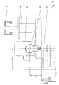
- FIG. 1 shows the fine material discharge space 1, to which the fine material outlet 2 is connected in a spatial position between separator wheel 3 and separator wheel storage 4.
- the prepareerrad 3 forms together with the prepareerradlagerung 4 and the drive 14 a structural unit, which is releasably connected by means of a bearing flange 5 via screws 8 with the mill 15.
- the bearing flange 5 forms a tight conclusion for the fines discharge space 1.
- the bearing flange 5 is centered over a fit 6 relative to the mill housing 7.
- the Mahlluftring horrides 16 is mounted externally on the mill housing 7 at the level of treaterrades 3. Over the circumference of the Mahlluftring effet 16 a plurality of connecting pieces 17 are arranged, to which elastic pressure hoses 9 are connected. The pressure hoses 9 lead the supplied via the Mahl Kunststoffring effet 16 via the terminal 21 compressed air to each jet nozzle 12. The pressure hoses 9 are detachably connected via additional connecting pieces 10 with the jet nozzles 12. The upper connecting pieces 17 are offset on the circumference relative to the lower connecting pieces 10, so that when loosening the screw 13 at the connecting pieces 10, the pressure hoses 9 pivot in a vertical position due to gravity and release the inlet openings to the jet nozzles 12 (see also Fig. 5).
- Fig. 2 the assembly of bearing flange 5, as well as storage 4 - and drive means 14 can be seen in the closed state.
- the belt drive 18 connects the drive device 14 with the bearing 4 and translates the rotational speed of the drive device 14 to a suitable speed for the separator wheel.
- the pivoting device shown in Fig. 3 allows rotation of the assembly of preparerrad 3, and storage 4 - and drive means 14 about the axis of rotation 19 by 180 °.
- the axis of rotation of the crushererrades 3 is then aligned vertically and the preparerrad 3 is accessible in an upwardly open position.
- the distance L and H of the axis of rotation 19 from the center of the cleaning opening 20 is selected so that the cleaning opening 20 is completely exposed and the interior is easily accessible.
- the opening operation of Fig. 4 is controlled so that the rotary drive and the vertical drive of the pivoting device can be moved simultaneously.
- the axis of rotation of the pivoting device is preferably in or as close as possible to the center of mass.
- a stop plate 23 is provided in the transition from the cylindrical grinding container wall of the mill 15 and the conical grinding container bottom 22, which has a transition rounding 24 at the inner radial edge.
- stopper plate 23 extending around the mill 15 are provided on the top and bottom of the stop plate, which reduce the stop plate 23 to the required wall thickness of Mahl alternerwand.
- the opening principle according to the invention can also be applied to mills with a beater mechanism, which however are not part of the present invention.
- the rotating working part 26 is equipped with impact beaters 27, which cooperates with a mounted on the inner circumference of the grinding containers Mahlbahn 28.
- Mahlgutholzgabe takes place via the inlet 29 into the feed space 30, from where the ground material is distributed to the impact beaters 27.
Landscapes
- Engineering & Computer Science (AREA)
- Food Science & Technology (AREA)
- Disintegrating Or Milling (AREA)
- Combined Means For Separation Of Solids (AREA)
- Crushing And Grinding (AREA)
- Paper (AREA)
- Finish Polishing, Edge Sharpening, And Grinding By Specific Grinding Devices (AREA)
Claims (9)
- Broyeur à contre-jets à lit fluidisé, composé :- d'un réservoir de broyage destiné à recevoir de la matière à broyer,- d'un nombre de buses à contre-jets (12) dirigées vers l'intérieur qui sont disposées dans la partie inférieure du réservoir de broyage et orientées de façon que les jets se rencontrent en un point commun pour broyer et fluidiser la matière à broyer se trouvant dans le réservoir de broyage,- d'un dispositif de séparation disposé dans la partie supérieure du réservoir de broyage avec une roue de séparateur (3) tournant autour d'un axe vertical, fonctionnant selon le principe de la force centrifuge pour séparer la matière broyée suffisamment finement de la matière à broyer,- d'un dispositif de support et d'entraînement (4, 14) pour la roue de séparateur rotative (3),- d'un chargement de matière servant à amener de la matière à broyer dans le réservoir de broyage,- d'une décharge de matière fine (1, 2) disposée au-dessus de la roue de séparateur (3), servant à évacuer du réservoir de broyage la matière séparée, broyée suffisamment finement,caractérisé en ce que la roue de séparateur (3) forme avec le dispositif de support et d'entraînement (4, 14) un ensemble structurel qui est relié de manière amovible au réservoir de broyage, l'ensemble structurel étant mobile par rapport au réservoir de broyage grâce à des dispositifs cinématiques de façon que la roue de séparateur (3) puisse être retirée du réservoir de broyage vers le haut à travers la décharge de matière fine (1, 2), la décharge de matière fine (1, 2) restant reliée au réservoir de broyage.
- Broyeur à contre-jets à lit fluidisé selon la revendication 1, caractérisé en ce que l'ensemble structurel formé par le dispositif de support et d'entraînement peut être déplacé linéairement en direction verticale par un dispositif de levage et amené à pivoter autour d'un axe situé dans le plan vertical par un dispositif de rotation.
- Broyeur à contre-jets à lit fluidisé selon la revendication 2, caractérisé en ce que le dispositif de levage est un vérin hydraulique et le dispositif de rotation un moteur hydraulique.
- Broyeur à contre-jets à lit fluidisé selon les revendications 1 à 3, caractérisé en ce que l'ensemble structurel formé par le dispositif de support et d'entraînement peut pivoter autour de son barycentre.
- Broyeur à contre-jets à lit fluidisé selon les revendications 1 à 3, caractérisé en ce que l'ensemble structurel formé par le dispositif de support et d'entraînement peut pivoter de 180°.
- Broyeur à contre-jets à lit fluidisé selon les revendications 1 à 3, caractérisé en ce que la position de l'axe de rotation de l'ensemble structurel est choisie de façon qu'après le pivotement de l'ensemble structurel, l'ouverture de nettoyage soit entièrement dégagée.
- Broyeur à contre-jets à lit fluidisé selon les revendications 1 à 3, caractérisé en ce que la conduite circulaire d'air de broyage est disposée au-dessus des buses d'éjection à hauteur de la roue de séparateur.
- Broyeur à contre-jets à lit fluidisé selon les revendications 1 à 3, caractérisé en ce que les raccords d'air de broyage sur le pourtour de la conduite circulaire d'air de broyage sont disposés en décalage par rapport aux raccords d'air de broyage des buses d'éjection.
- Broyeur à contre-jets à lit fluidisé selon les revendications 1 à 3, caractérisé en ce qu'entre la paroi cylindrique de réservoir de broyage et le fond conique de réservoir de broyage est prévue une plaque de butée qui présente un arrondi de transition sur le bord radial intérieur et est soudée à joint abouté avec la paroi cylindrique de réservoir de broyage et le fond conique de réservoir de broyage.
Applications Claiming Priority (2)
| Application Number | Priority Date | Filing Date | Title |
|---|---|---|---|
| DE10033628A DE10033628A1 (de) | 2000-07-11 | 2000-07-11 | Fliessbett-Gegenstrahlmühle |
| DE10033628 | 2000-07-11 |
Publications (2)
| Publication Number | Publication Date |
|---|---|
| EP1172149A1 EP1172149A1 (fr) | 2002-01-16 |
| EP1172149B1 true EP1172149B1 (fr) | 2007-12-26 |
Family
ID=7648523
Family Applications (1)
| Application Number | Title | Priority Date | Filing Date |
|---|---|---|---|
| EP01114088A Expired - Lifetime EP1172149B1 (fr) | 2000-07-11 | 2001-06-09 | Broyeur à contre-jets à lit fluidisé |
Country Status (6)
| Country | Link |
|---|---|
| US (1) | US6543710B2 (fr) |
| EP (1) | EP1172149B1 (fr) |
| JP (1) | JP4778636B2 (fr) |
| AT (1) | ATE381967T1 (fr) |
| DE (2) | DE10033628A1 (fr) |
| ES (1) | ES2295085T4 (fr) |
Families Citing this family (21)
| Publication number | Priority date | Publication date | Assignee | Title |
|---|---|---|---|---|
| JP2006091175A (ja) | 2004-09-21 | 2006-04-06 | Kao Corp | トナーの製造方法 |
| US7449275B2 (en) | 2004-09-21 | 2008-11-11 | Kao Corporation | Process for preparing toner |
| US7560218B2 (en) | 2004-10-01 | 2009-07-14 | Kao Corporation | Process for preparing toner |
| JP4491328B2 (ja) * | 2004-10-29 | 2010-06-30 | 花王株式会社 | トナーの製造方法 |
| US20100221540A1 (en) * | 2006-02-24 | 2010-09-02 | Vitrabio Gmbh | Process for Producing a Porous Glass and Glass Powder and Glass Material for Carrying Out the Process |
| US8858699B2 (en) | 2006-07-13 | 2014-10-14 | Unimin Corporation | Ultra fine nepheline syenite powder and products for using same |
| US20080040980A1 (en) * | 2006-07-13 | 2008-02-21 | Unimin Corporation | Method of processing nepheline syenite |
| US20080015104A1 (en) * | 2006-07-13 | 2008-01-17 | Unimin Corporation | Ultrafine nepheline syenite |
| US7757976B2 (en) * | 2007-02-07 | 2010-07-20 | Unimin Corporation | Method of processing nepheline syenite powder to produce an ultra-fine grain size product |
| CA2691830C (fr) * | 2007-07-09 | 2014-07-29 | Unimin Corporation | Poudre de syenite nephelinique ayant une taille de particules regulee et son nouveau procede de fabrication |
| JP5246914B2 (ja) | 2007-11-26 | 2013-07-24 | 花王株式会社 | トナーの製造方法 |
| US8182601B2 (en) * | 2008-04-17 | 2012-05-22 | Unimin Corporation | Powder formed from mineral or rock material with controlled particle size distribution for thermal films |
| DE102008030749B4 (de) * | 2008-06-27 | 2019-03-07 | Hosokawa Alpine Ag | Mahlvorrichtung mit Mühle als Einbaumodul |
| US8091817B2 (en) * | 2009-12-11 | 2012-01-10 | Flsmidth A/S | Milling device |
| ITMI20120092A1 (it) * | 2012-01-26 | 2013-07-27 | Micro Macinazione S A | Compositi di inclusione farmaco-carrier preparati con processo di attivazione meccano-chimica mediante mulini a getto di fluido ad alta energia |
| DE102018008127B4 (de) | 2018-10-13 | 2022-06-09 | Hosokawa Alpine Aktiengesellschaft | Blaskopf und Verfahren zur Herstellung einer Mehrschichtschlauchfolie |
| DE102018009632B4 (de) | 2018-12-11 | 2021-12-09 | Hosokawa Alpine Aktiengesellschaft | Vorrichtung zum Aufwickeln und Wickelwechsel von bahnförmigem Material und ein Verfahren dafür |
| DE102020000334A1 (de) | 2020-01-21 | 2021-07-22 | Hosokawa Alpine Aktiengesellschaft | Vorrichtung und Verfahren zur monaxialen Längenänderung von Folienbahnen |
| DE102020006008B3 (de) | 2020-10-01 | 2022-03-31 | Hosokawa Alpine Aktiengesellschaft | Fließbettgegenstrahlmühle zur Erzeugung feinster Partikel aus Aufgabegut geringer Schüttdichte und Verfahren dafür |
| CN114011715B (zh) * | 2021-12-14 | 2022-12-06 | 昆山强威粉体设备有限公司 | 流化床对撞式气流粉碎机的分级轮负压出料装置 |
| DE102022000351A1 (de) | 2022-01-29 | 2023-08-03 | Hosokawa Alpine Aktiengesellschaft | Verfahren und Vorrichtung zur Foliendickenregelung von gereckter im Folienblasverfahren hergestellter Schlauchfolie |
Family Cites Families (11)
| Publication number | Priority date | Publication date | Assignee | Title |
|---|---|---|---|---|
| US4018388A (en) * | 1976-05-13 | 1977-04-19 | Andrews Norwood H | Jet-type axial pulverizer |
| DE2641620C3 (de) * | 1976-09-16 | 1987-07-09 | Krupp Polysius Ag, 4720 Beckum | Rollenmühle mit Sichter |
| DE3140294C2 (de) * | 1981-10-10 | 1983-11-17 | Alpine Ag, 8900 Augsburg | Verfahren und Vorrichtung zum Trennen eines Gutgemisches in Komponenten unterschiedlicher Mahlbarkeit |
| DE3338138C2 (de) * | 1983-10-20 | 1986-01-16 | Alpine Ag, 8900 Augsburg | Fließbett-Gegenstrahlmühle |
| JPH074557B2 (ja) * | 1990-10-23 | 1995-01-25 | 株式会社栗本鐵工所 | 粉砕媒体を使用した気流粉砕方法 |
| DE4100338A1 (de) * | 1991-01-08 | 1992-07-09 | Nied Roland | Verfahren zum ermitteln des grades der befuellung eines behaelters |
| JPH05212308A (ja) * | 1992-01-31 | 1993-08-24 | Fuji Xerox Co Ltd | 微粉砕装置および粉砕方法 |
| JPH0615193A (ja) * | 1992-04-07 | 1994-01-25 | Kyowa Shokuhin:Kk | ジェットミル |
| JP3179389B2 (ja) * | 1997-10-09 | 2001-06-25 | ホソカワミクロン株式会社 | 分級機 |
| JP2000140674A (ja) * | 1998-11-13 | 2000-05-23 | Iec:Kk | 気流式粉砕機 |
| US6398139B1 (en) * | 1999-08-23 | 2002-06-04 | Roland Nied | Process for fluidized-bed jet milling, device for carrying out this process and unit with such a device for carrying out this process |
-
2000
- 2000-07-11 DE DE10033628A patent/DE10033628A1/de not_active Withdrawn
-
2001
- 2001-06-09 ES ES01114088T patent/ES2295085T4/es not_active Expired - Lifetime
- 2001-06-09 AT AT01114088T patent/ATE381967T1/de not_active IP Right Cessation
- 2001-06-09 EP EP01114088A patent/EP1172149B1/fr not_active Expired - Lifetime
- 2001-06-09 DE DE50113409T patent/DE50113409D1/de not_active Expired - Lifetime
- 2001-07-09 JP JP2001208449A patent/JP4778636B2/ja not_active Expired - Lifetime
- 2001-07-09 US US09/901,395 patent/US6543710B2/en not_active Expired - Lifetime
Also Published As
| Publication number | Publication date |
|---|---|
| EP1172149A1 (fr) | 2002-01-16 |
| DE10033628A1 (de) | 2002-01-24 |
| ATE381967T1 (de) | 2008-01-15 |
| JP4778636B2 (ja) | 2011-09-21 |
| US20020011534A1 (en) | 2002-01-31 |
| US6543710B2 (en) | 2003-04-08 |
| DE50113409D1 (de) | 2008-02-07 |
| JP2002035631A (ja) | 2002-02-05 |
| ES2295085T4 (es) | 2008-06-16 |
| ES2295085T3 (es) | 2008-04-16 |
Similar Documents
| Publication | Publication Date | Title |
|---|---|---|
| EP1172149B1 (fr) | Broyeur à contre-jets à lit fluidisé | |
| DE3338138C2 (de) | Fließbett-Gegenstrahlmühle | |
| EP2632599B1 (fr) | Broyeur à boulets avec agitateur | |
| DE19635500A1 (de) | Vorrichtung zur Hochenergie- und/oder Feinstmahlung von Feststoffen und Verfahren zu dessen Betrieb | |
| DE2550879C3 (de) | Vorrichtung zur bekannten Wiederverwertung des Abfalls von wärmegehärtetem Kunststoff | |
| EP0700722A1 (fr) | Broyeur agitateur | |
| EP3615236B1 (fr) | Système d'une machine de mélange industrielle comprenant une tête de mélange et un récipient de nettoyage | |
| DE3140294C2 (de) | Verfahren und Vorrichtung zum Trennen eines Gutgemisches in Komponenten unterschiedlicher Mahlbarkeit | |
| EP0261241B1 (fr) | Desintegrateur | |
| DE19504540A1 (de) | Vorrichtung zum Beschichten oder Entleeren eines Behälters, insbesondere eines mit Mahlkörpern diskontinuierlich arbeitenden Mahlaggregats | |
| DE19913243A1 (de) | Mahlvorrichtung zur Hochenergie- und/oder Feinstmahlung von Feststoffen mit schwenkbarem Mahlbehälter | |
| DE3490555C2 (fr) | ||
| DE3308390C2 (de) | Schleifzerkleinerer | |
| DE4402609C2 (de) | Rührwerkskugelmühle | |
| DE102013002237B3 (de) | Sichtermühle | |
| DE19819967A1 (de) | Rührwerksmühle | |
| EP0359942A2 (fr) | Machine pour le traitement des matériaux en vrac, pâteux et/ou coulants avec dispositif de préparation installé | |
| DE3131370C2 (fr) | ||
| DE4319702C2 (de) | Prallbrecher | |
| DE19520325C2 (de) | Sichtermühle | |
| DE19718668C2 (de) | Verfahren zum Trennen und kontinuierlichen Austragen von schwer dispergierbaren Bestandteilen | |
| EP0813944A2 (fr) | Broyeur pour la pulvérisation de matières solides | |
| EP3209435A1 (fr) | Dispositif de tri destiné à trier un flux de matériaux granulaires | |
| EP3789118B1 (fr) | Broyeur à chocs destiné au concassage des solides | |
| DE10110652A1 (de) | Rührwerksmühle mit torusförmigem Mahlspalt |
Legal Events
| Date | Code | Title | Description |
|---|---|---|---|
| PUAI | Public reference made under article 153(3) epc to a published international application that has entered the european phase |
Free format text: ORIGINAL CODE: 0009012 |
|
| AK | Designated contracting states |
Kind code of ref document: A1 Designated state(s): AT BE CH CY DE DK ES FI FR GB GR IE IT LI LU MC NL PT SE TR |
|
| AX | Request for extension of the european patent |
Free format text: AL;LT;LV;MK;RO;SI |
|
| 17P | Request for examination filed |
Effective date: 20011220 |
|
| AKX | Designation fees paid |
Free format text: AT BE CH CY DE DK ES FI FR GB GR IE IT LI LU MC NL PT SE TR |
|
| RAP1 | Party data changed (applicant data changed or rights of an application transferred) |
Owner name: HOSOKAWA ALPINE AKTIENGESELLSCHAFT |
|
| GRAP | Despatch of communication of intention to grant a patent |
Free format text: ORIGINAL CODE: EPIDOSNIGR1 |
|
| GRAS | Grant fee paid |
Free format text: ORIGINAL CODE: EPIDOSNIGR3 |
|
| GRAA | (expected) grant |
Free format text: ORIGINAL CODE: 0009210 |
|
| AK | Designated contracting states |
Kind code of ref document: B1 Designated state(s): AT BE CH CY DE DK ES FI FR GB GR IE IT LI LU MC NL PT SE TR |
|
| REG | Reference to a national code |
Ref country code: GB Ref legal event code: FG4D Free format text: NOT ENGLISH |
|
| REG | Reference to a national code |
Ref country code: IE Ref legal event code: FG4D Free format text: LANGUAGE OF EP DOCUMENT: GERMAN |
|
| REG | Reference to a national code |
Ref country code: CH Ref legal event code: EP Ref country code: CH Ref legal event code: NV Representative=s name: LUCHS & PARTNER PATENTANWAELTE |
|
| REF | Corresponds to: |
Ref document number: 50113409 Country of ref document: DE Date of ref document: 20080207 Kind code of ref document: P |
|
| REG | Reference to a national code |
Ref country code: ES Ref legal event code: FG2A Ref document number: 2295085 Country of ref document: ES Kind code of ref document: T3 |
|
| GBT | Gb: translation of ep patent filed (gb section 77(6)(a)/1977) |
Effective date: 20080403 |
|
| PG25 | Lapsed in a contracting state [announced via postgrant information from national office to epo] |
Ref country code: SE Free format text: LAPSE BECAUSE OF FAILURE TO SUBMIT A TRANSLATION OF THE DESCRIPTION OR TO PAY THE FEE WITHIN THE PRESCRIBED TIME-LIMIT Effective date: 20080326 |
|
| PG25 | Lapsed in a contracting state [announced via postgrant information from national office to epo] |
Ref country code: FI Free format text: LAPSE BECAUSE OF FAILURE TO SUBMIT A TRANSLATION OF THE DESCRIPTION OR TO PAY THE FEE WITHIN THE PRESCRIBED TIME-LIMIT Effective date: 20071226 |
|
| PG25 | Lapsed in a contracting state [announced via postgrant information from national office to epo] |
Ref country code: PT Free format text: LAPSE BECAUSE OF FAILURE TO SUBMIT A TRANSLATION OF THE DESCRIPTION OR TO PAY THE FEE WITHIN THE PRESCRIBED TIME-LIMIT Effective date: 20080526 |
|
| PG25 | Lapsed in a contracting state [announced via postgrant information from national office to epo] |
Ref country code: DK Free format text: LAPSE BECAUSE OF FAILURE TO SUBMIT A TRANSLATION OF THE DESCRIPTION OR TO PAY THE FEE WITHIN THE PRESCRIBED TIME-LIMIT Effective date: 20071226 |
|
| PGFP | Annual fee paid to national office [announced via postgrant information from national office to epo] |
Ref country code: IE Payment date: 20080508 Year of fee payment: 8 Ref country code: NL Payment date: 20080610 Year of fee payment: 8 |
|
| PLBE | No opposition filed within time limit |
Free format text: ORIGINAL CODE: 0009261 |
|
| STAA | Information on the status of an ep patent application or granted ep patent |
Free format text: STATUS: NO OPPOSITION FILED WITHIN TIME LIMIT |
|
| 26N | No opposition filed |
Effective date: 20080929 |
|
| BERE | Be: lapsed |
Owner name: HOSOKAWA ALPINE A.G. Effective date: 20080630 |
|
| PGFP | Annual fee paid to national office [announced via postgrant information from national office to epo] |
Ref country code: GB Payment date: 20080512 Year of fee payment: 8 |
|
| PG25 | Lapsed in a contracting state [announced via postgrant information from national office to epo] |
Ref country code: GR Free format text: LAPSE BECAUSE OF FAILURE TO SUBMIT A TRANSLATION OF THE DESCRIPTION OR TO PAY THE FEE WITHIN THE PRESCRIBED TIME-LIMIT Effective date: 20080327 Ref country code: MC Free format text: LAPSE BECAUSE OF NON-PAYMENT OF DUE FEES Effective date: 20080630 |
|
| PG25 | Lapsed in a contracting state [announced via postgrant information from national office to epo] |
Ref country code: BE Free format text: LAPSE BECAUSE OF NON-PAYMENT OF DUE FEES Effective date: 20080630 |
|
| PG25 | Lapsed in a contracting state [announced via postgrant information from national office to epo] |
Ref country code: CY Free format text: LAPSE BECAUSE OF FAILURE TO SUBMIT A TRANSLATION OF THE DESCRIPTION OR TO PAY THE FEE WITHIN THE PRESCRIBED TIME-LIMIT Effective date: 20071226 |
|
| PG25 | Lapsed in a contracting state [announced via postgrant information from national office to epo] |
Ref country code: AT Free format text: LAPSE BECAUSE OF NON-PAYMENT OF DUE FEES Effective date: 20080609 |
|
| GBPC | Gb: european patent ceased through non-payment of renewal fee |
Effective date: 20090609 |
|
| NLV4 | Nl: lapsed or anulled due to non-payment of the annual fee |
Effective date: 20100101 |
|
| PG25 | Lapsed in a contracting state [announced via postgrant information from national office to epo] |
Ref country code: IE Free format text: LAPSE BECAUSE OF NON-PAYMENT OF DUE FEES Effective date: 20090609 |
|
| PG25 | Lapsed in a contracting state [announced via postgrant information from national office to epo] |
Ref country code: GB Free format text: LAPSE BECAUSE OF NON-PAYMENT OF DUE FEES Effective date: 20090609 |
|
| PG25 | Lapsed in a contracting state [announced via postgrant information from national office to epo] |
Ref country code: NL Free format text: LAPSE BECAUSE OF NON-PAYMENT OF DUE FEES Effective date: 20100101 Ref country code: LU Free format text: LAPSE BECAUSE OF NON-PAYMENT OF DUE FEES Effective date: 20080609 |
|
| PG25 | Lapsed in a contracting state [announced via postgrant information from national office to epo] |
Ref country code: TR Free format text: LAPSE BECAUSE OF FAILURE TO SUBMIT A TRANSLATION OF THE DESCRIPTION OR TO PAY THE FEE WITHIN THE PRESCRIBED TIME-LIMIT Effective date: 20071226 |
|
| PGFP | Annual fee paid to national office [announced via postgrant information from national office to epo] |
Ref country code: CH Payment date: 20110614 Year of fee payment: 11 |
|
| REG | Reference to a national code |
Ref country code: CH Ref legal event code: PL |
|
| REG | Reference to a national code |
Ref country code: CH Ref legal event code: PL |
|
| PG25 | Lapsed in a contracting state [announced via postgrant information from national office to epo] |
Ref country code: CH Free format text: LAPSE BECAUSE OF NON-PAYMENT OF DUE FEES Effective date: 20120630 Ref country code: LI Free format text: LAPSE BECAUSE OF NON-PAYMENT OF DUE FEES Effective date: 20120630 |
|
| REG | Reference to a national code |
Ref country code: FR Ref legal event code: PLFP Year of fee payment: 15 |
|
| PGFP | Annual fee paid to national office [announced via postgrant information from national office to epo] |
Ref country code: ES Payment date: 20150512 Year of fee payment: 15 |
|
| PGFP | Annual fee paid to national office [announced via postgrant information from national office to epo] |
Ref country code: FR Payment date: 20150608 Year of fee payment: 15 |
|
| PGFP | Annual fee paid to national office [announced via postgrant information from national office to epo] |
Ref country code: IT Payment date: 20160621 Year of fee payment: 16 |
|
| REG | Reference to a national code |
Ref country code: FR Ref legal event code: ST Effective date: 20170228 |
|
| PG25 | Lapsed in a contracting state [announced via postgrant information from national office to epo] |
Ref country code: FR Free format text: LAPSE BECAUSE OF NON-PAYMENT OF DUE FEES Effective date: 20160630 |
|
| PGFP | Annual fee paid to national office [announced via postgrant information from national office to epo] |
Ref country code: DE Payment date: 20170605 Year of fee payment: 17 |
|
| PG25 | Lapsed in a contracting state [announced via postgrant information from national office to epo] |
Ref country code: IT Free format text: LAPSE BECAUSE OF NON-PAYMENT OF DUE FEES Effective date: 20170609 Ref country code: ES Free format text: LAPSE BECAUSE OF NON-PAYMENT OF DUE FEES Effective date: 20160610 |
|
| REG | Reference to a national code |
Ref country code: ES Ref legal event code: FD2A Effective date: 20181130 |
|
| REG | Reference to a national code |
Ref country code: DE Ref legal event code: R119 Ref document number: 50113409 Country of ref document: DE |
|
| PG25 | Lapsed in a contracting state [announced via postgrant information from national office to epo] |
Ref country code: DE Free format text: LAPSE BECAUSE OF NON-PAYMENT OF DUE FEES Effective date: 20190101 |