EP1172247B1 - Schaltvorrichtung für hohe Fahrzeuggeschwindigkeiten - Google Patents
Schaltvorrichtung für hohe Fahrzeuggeschwindigkeiten Download PDFInfo
- Publication number
- EP1172247B1 EP1172247B1 EP01202490A EP01202490A EP1172247B1 EP 1172247 B1 EP1172247 B1 EP 1172247B1 EP 01202490 A EP01202490 A EP 01202490A EP 01202490 A EP01202490 A EP 01202490A EP 1172247 B1 EP1172247 B1 EP 1172247B1
- Authority
- EP
- European Patent Office
- Prior art keywords
- gear
- transmission
- shaft
- pto
- vehicle
- Prior art date
- Legal status (The legal status is an assumption and is not a legal conclusion. Google has not performed a legal analysis and makes no representation as to the accuracy of the status listed.)
- Expired - Lifetime
Links
- 230000005540 biological transmission Effects 0.000 claims abstract description 40
- 230000007246 mechanism Effects 0.000 claims description 10
- 230000008878 coupling Effects 0.000 claims description 4
- 238000010168 coupling process Methods 0.000 claims description 4
- 238000005859 coupling reaction Methods 0.000 claims description 4
- 230000007935 neutral effect Effects 0.000 claims description 4
- 230000008859 change Effects 0.000 claims description 2
- 230000003213 activating effect Effects 0.000 description 2
- 230000004075 alteration Effects 0.000 description 2
- 230000004913 activation Effects 0.000 description 1
- 239000010426 asphalt Substances 0.000 description 1
- 230000008901 benefit Effects 0.000 description 1
- 239000012141 concentrate Substances 0.000 description 1
- 239000006185 dispersion Substances 0.000 description 1
- 230000000694 effects Effects 0.000 description 1
- 230000014759 maintenance of location Effects 0.000 description 1
Images


Classifications
-
- B—PERFORMING OPERATIONS; TRANSPORTING
- B60—VEHICLES IN GENERAL
- B60K—ARRANGEMENT OR MOUNTING OF PROPULSION UNITS OR OF TRANSMISSIONS IN VEHICLES; ARRANGEMENT OR MOUNTING OF PLURAL DIVERSE PRIME-MOVERS IN VEHICLES; AUXILIARY DRIVES FOR VEHICLES; INSTRUMENTATION OR DASHBOARDS FOR VEHICLES; ARRANGEMENTS IN CONNECTION WITH COOLING, AIR INTAKE, GAS EXHAUST OR FUEL SUPPLY OF PROPULSION UNITS IN VEHICLES
- B60K17/00—Arrangement or mounting of transmissions in vehicles
- B60K17/04—Arrangement or mounting of transmissions in vehicles characterised by arrangement, location or kind of gearing
- B60K17/06—Arrangement or mounting of transmissions in vehicles characterised by arrangement, location or kind of gearing of change-speed gearing
- B60K17/08—Arrangement or mounting of transmissions in vehicles characterised by arrangement, location or kind of gearing of change-speed gearing of mechanical type
-
- B—PERFORMING OPERATIONS; TRANSPORTING
- B60—VEHICLES IN GENERAL
- B60K—ARRANGEMENT OR MOUNTING OF PROPULSION UNITS OR OF TRANSMISSIONS IN VEHICLES; ARRANGEMENT OR MOUNTING OF PLURAL DIVERSE PRIME-MOVERS IN VEHICLES; AUXILIARY DRIVES FOR VEHICLES; INSTRUMENTATION OR DASHBOARDS FOR VEHICLES; ARRANGEMENTS IN CONNECTION WITH COOLING, AIR INTAKE, GAS EXHAUST OR FUEL SUPPLY OF PROPULSION UNITS IN VEHICLES
- B60K17/00—Arrangement or mounting of transmissions in vehicles
- B60K17/28—Arrangement or mounting of transmissions in vehicles characterised by arrangement, location, or type of power take-off
-
- Y—GENERAL TAGGING OF NEW TECHNOLOGICAL DEVELOPMENTS; GENERAL TAGGING OF CROSS-SECTIONAL TECHNOLOGIES SPANNING OVER SEVERAL SECTIONS OF THE IPC; TECHNICAL SUBJECTS COVERED BY FORMER USPC CROSS-REFERENCE ART COLLECTIONS [XRACs] AND DIGESTS
- Y10—TECHNICAL SUBJECTS COVERED BY FORMER USPC
- Y10T—TECHNICAL SUBJECTS COVERED BY FORMER US CLASSIFICATION
- Y10T74/00—Machine element or mechanism
- Y10T74/19—Gearing
- Y10T74/19023—Plural power paths to and/or from gearing
- Y10T74/19074—Single drive plural driven
- Y10T74/19112—Aligned
- Y10T74/19116—Vehicle
-
- Y—GENERAL TAGGING OF NEW TECHNOLOGICAL DEVELOPMENTS; GENERAL TAGGING OF CROSS-SECTIONAL TECHNOLOGIES SPANNING OVER SEVERAL SECTIONS OF THE IPC; TECHNICAL SUBJECTS COVERED BY FORMER USPC CROSS-REFERENCE ART COLLECTIONS [XRACs] AND DIGESTS
- Y10—TECHNICAL SUBJECTS COVERED BY FORMER USPC
- Y10T—TECHNICAL SUBJECTS COVERED BY FORMER US CLASSIFICATION
- Y10T74/00—Machine element or mechanism
- Y10T74/19—Gearing
- Y10T74/19219—Interchangeably locked
- Y10T74/19251—Control mechanism
Definitions
- the present invention relates to a vehicle comprising a high vehicle speed shift device.
- Still other known solutions consist in a transmission comprising two subsystems: a first subsystem for achieving a given speed range, and a second subsystem for achieving higher speeds up to a maximum of 50 km/h.
- the outcome is a highly complex transmission.
- US-A-4.961.721 discloses a device transmitting power to the rear power take-off (PTO) of the tractor according to the preamble of claim 1.
- a vehicle comprising a frame, an engine, a transmission with clutches and operable to select a number of vehicle speeds, and a device for transmitting power from said engine to a PTO; said device including a high speed mechanism which is capable of selecting a higher vehicle speed which is greater than any of said number of vehicle speeds selectable by said transmission; the connection of said high speed mechanism causing said transmission clutches to automatically disengage, but involving no other change in said transmission in order to select said higher vehicle speed; and said high speed mechanism including first and second gears having a velocity ratio corresponding to said higher vehicle speed.
- the vehicle is characterized in that said first gear rests idly on a shaft forming part of said high speed mechanism when said higher vehicle speed is not selected and is made integral with said shaft when said higher vehicle speed is selected.
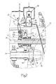
- Reference number 10 in Figure 1 indicates as a whole a unit for transmitting power to the drive wheels and rear power take-off (PTO) of an agricultural tractor, which is shown only partly.
- Unit 10 can be divided theoretically into a standard transmission 11, and a device 12 for transmitting power from an engine (not shown) via a rear power take-off (PTC) 13 comprising a series of gears 13a and a countershaft 13b towards an implement (not shown).
- PTC rear power take-off
- Power is transmitted from the engine to an intermediate shaft 14 by conventional transmission means described briefly below. More particularly, by means of three groups 16a, 16b, 16c of gears provided with respective clutches, power is transmitted from the engine to a ring gear 15 which, in turn, rotatably drives two rear drive wheels (not shown) of the tractor.
- the three groups 16a, 16b, 16c of gears form the standard transmission 11.
- the Figure 1 embodiment shows a so-called "Full Power Shift" transmission of which the operating principle is well known in the art and which, in the present case, supplies the tractor with eighteen forward speeds and six reverse speeds.
- Transmission 11 as a whole operates in a known manner and is therefore not described in detail.
- unit 10 further comprises a clutch 18 which, when activated by the operator, transmits power to the front wheels (not shown) to operate the tractor in "four-wheel-drive".
- Intermediate shaft 14 has two ends 14a, 14b, of which end 14b is fitted with a bevel pinion 19 meshing permanently with ring gear 15 which, as stated, directly powers the rear wheels (not shown) of the tractor. Power is actually transmitted from the engine to intermediate shaft 14 through a shaft 20, which forms part of device 12 and provides for transmitting power to the rear PTO 13.
- Shaft 20 has a longitudinal axis of symmetry A, and is provided with a flywheel 20a with an associated flexible coupling 20b.
- a clutch 21 and brake 22, controlled by respective solenoid valves 23 and 24 as described in detail further on, are located between shaft 20 and PTO 13, and are operable, among other things (see below), to connect and disconnect PTO 13 to and from shaft 20 under control of the operator.
- shaft 20 moreover is provided with a device 25 for connecting a gear 26 integrally to shaft 20, as described in detail later on.
- shaft 20 is housed inside a sleeve 17 coaxial with axis A of shaft 20.
- the sleeve 17 is supported by the tractor frame by means of a ball bearing 17a and is connected to clutch 21 of PTO 13.
- Gear 26 is in actual fact fitted idly to sleeve 17 by means of a ball bearing 27.
- Sleeve 17 extends between clutch 21 at one end, and an integral hub 35 at the other end.
- Device 25 comprises a solenoid valve 28 for controlling the position of a piston 29 forming part of a hydraulic cylinder 30 supplied with oil under pressure by a utility line 31, e.g. at 17-18 bar pressure.
- Piston 29 is connected to a rod 32 which acts on a lever 33 rotating about a fixed pin 34.
- One end of lever 33 is hinged in a particular way (see below) to an internally toothed sleeve 33b, the teeth of which (not shown) mesh with grooves (not shown) on gear 26 to connect gear 26 integrally to sleeve 33b, and therefore to shaft 20, by means of hub 35, sleeve 17 and clutch 21.
- Sleeve 33b must obviously be so connected to lever 33 as to enable sleeve 33b to rotate in unison with gear 26 with no interference from lever 33, which, as stated, can only rotate about pin 34 when activated by rod 32.
- the bottom end 33a of lever 33 is provided with a fork (not shown) having pads (not shown) which engage in a known manner a circular groove (not shown) formed on the outer surface of sleeve 33b.
- gear 26 When gear 26 is made integral with shaft 20 as described above, i.e. when toothed sleeve 33b is connected to the gear 26 and to the hub 35, rotation of shaft 20 is transmitted to a gear 36 integral with shaft 14. In this manner, power is transmitted to bevel pinion 19 and from there onwards to ring gear 15 to engage a nineteenth forward gear corresponding to maximum tractor speed, e.g. 50 km/h. At the same time, obviously to avoid ratio interference, the clutches of the three groups 16a, 16b, 16c of gears of the standard transmission 11 are all disengaged.
- Central control unit 40 is connected electronically to a series of switches 41, 42, 44 and a push-button control 43, the function of which is described later on in connection with the operation of unit 10.
- the first operating mode is a so-called "PTO mode".
- PTO mode the operator can select one of the eighteen forward speeds or one of the six reverse speeds in the usual way using standard transmission 11, and at the same time use PTO 13 by means of device 12.
- switch 41 for selecting "PTO mode” or a “full speed mode” (see below), is set by the operator to "PTO mode".
- Solenoid valve 28 is set to "OFF", so that only chamber 30a of cylinder 30 is supplied with pressurized oil over line 31.
- Lever 33 rotates clockwise, so that sleeve 33b is disconnected from gear 26, which, supported on bearing 27, rests idly on sleeve 17.
- a switch 45 supplies electronic central control unit 40 with the information necessary to determine the position of sleeve 33b.
- a double hydraulic cylinder 46 of PTO 13, shown in Figure 1 is not subjected to any hydraulic stress, so that, by means of a manual control 47, the ratio of PTO 13 can be set, for example, at either 540 or at 1000 rpm.
- the selected ratio is transmitted to central control unit 40 by a switch 48.
- solenoid valve 23 for engaging and releasing clutch 21 remains in the "OFF” position so that the clutch 21 is released, while solenoid valve 24 for engaging and releasing brake 22 of PTO 13 remains in the "ON” position so that brake 22 is engaged.
- switch 42 can switch solenoid valve 23 to the "ON” condition and solenoid valve 24 to the "OFF” condition to engage clutch 21 and simultaneously release brake 22, so that power is transmitted by device 12 from the engine to PTO 13.
- PTO 13 is selectively activated or deactivated by means of switch 42, which acts on solenoid valves 23, 24 following operator selection of "PTO mode” or "full speed mode” by means of switch 41.
- a switch 44 in addition is provided to enable the operator to disable brake 22 even when clutch 21 is released. This is especially useful when a rotating implement with a high inertial mass is attached to PTO 13, as in this case, engaging brake 22 with rotating masses attached to shaft 13b of PTO 13 could result in wear of brake 22.
- PTO mode the operator can select from eighteen forward and six reverse tractor speeds using standard transmission 11, and at the same time may or may not operate PTO 13 by means of switch 42. Gearshifting is obviously performed by means of push-button control 43.
- gear 26 is made integral, as described previously, with shaft 20 to transmit power from shaft 20 to bevel pinion 19, and therefrom to ring gear 15, to shift into maximum vehicle speed which, as stated, may be 50 km/h.
- This nineteenth gear is again engaged by the operator using push-button control 43.
- shaft 20 which is normally only used to transmit power to PTO 13 is now used by the operator to shift the vehicle wheels into nineteenth gear using push-button shift control 43, which acts depending on activation or de-activation of solenoid valve 23 and clutch 21. Also under this condition switch 45 supplies central control unit 40 with the necessary information to determine the position of sleeve 33b in direction X.
- a pressurized-oil feed line 37 is provided between solenoid valve 28 and double cylinder 46.
- Double cylinder 46 having the same pressure on both sides 46a, 46b by solenoid valve 28 being set to “ON”, centers shift control 47 into neutral, which is detected by switch 48.
- Solenoid valve 23 will be set to "ON”, so that clutch 21 will be engaged when the nineteenth gear is selected, while solenoid valve 24 is set to "OFF", i.e. brake 22 is released.
- the maximum speed of e.g. 50 km/h is again selected by the operator using push-button control 43.
- FIG 3 shows a second embodiment of the present invention.
- device 25 is replaced by a device 50 for making gear 26 selectively integral with shaft 20.
- device 50 operates on a different principle, it nevertheless has exactly the same effect on gear 26 as device 25 described with reference to Figures 1 and 2.
- Device 50 comprises two pressurized-oil feed channels 51 formed in shaft 20 which serve to feed oil to a bell shaped housing 52 integral with shaft 20 and coaxial with axis A.
- the housing 52 has an inner chamber 53 and houses a piston 54.
- Chamber 53 is fed with pressurized oil along channels 51 to move piston 54 rightwards, with reference to Figure 3, in direction X.
- Piston 54 is connected by known means to a cylindrical member 55 from which a pack of annular plates 56 project inwardly and perpendicularly to axis A of shaft 20.
- gear 26 has a hub 57, from which outwardly project annular plates 58 alternating with plates 56, which, as already mentioned, are integral with cylindrical member 55, in turn integral with piston 54.
- Piston 54 is stressed elastically by a spring 59, coaxial with axis A, which tends to restore piston 54 to its original position.
- switch 41 of the first embodiment of Figures 1 and 2 is dispensed with, since no mode selection is required.
- central control unit 40 commands pressurized-oil feed to chamber 53 via channels 51 and a solenoid valve (not shown).
- the oil entering chamber 53 moves piston 54 and integral cylindrical member 55 rightwards, with reference to Figure 3, so that each plate 56 is also moved rightwards into contact with the surface of an adjacent plate 58 integral with hub 57. If, therefore, during rotation, plates 56 do not slide with respect to plates 58, gear 26 acts as if it were unitary with shaft 20, as opposed to being idly fitted thereto.
- gear 26 is no longer idle with respect to shaft 20
- power can be transmitted from shaft 20 to gear 36 to rotate bevel pinion 19 meshing permanently with ring gear 15 of the tractor wheels.
- the velocity ratio between gear 26 and gear 36 is obviously such as to achieve the desired maximum speed of the rear wheels of the tractor.
- the main advantage of unit 10 of the tractor according to the present invention lies in the possibility of shifting to a fairly high speed (e.g. 50 km/h) using shaft 20 of the PTO power transmission device 12.
- end users may choose between a version with no device 25 or 50, and a possibly more expensive version designed for a maximum speed of 50 km/h, with no alterations to transmission 11, which may remain standard for all models.
Landscapes
- Engineering & Computer Science (AREA)
- Combustion & Propulsion (AREA)
- Transportation (AREA)
- Mechanical Engineering (AREA)
- Chemical & Material Sciences (AREA)
- Arrangement And Driving Of Transmission Devices (AREA)
- Structure Of Transmissions (AREA)
- Arrangement Or Mounting Of Control Devices For Change-Speed Gearing (AREA)
- Control Of Transmission Device (AREA)
- Vehicle Body Suspensions (AREA)
- Amplifiers (AREA)
- Control Of Eletrric Generators (AREA)
- Electronic Switches (AREA)
Claims (9)
- Fahrzeug mit einem Rahmen, einem Motor, einem Getriebe (11) mit Kupplungen, das betreibbar ist, um eine Anzahl von Fahrzeug-Gängen auszuwählen, und mit einer Vorrichtung (12) zur Übertragung von Leistung von dem Motor zu einer PTO- (Zapfwellen-) Einrichtung (13), wobei die Vorrichtung (12) einen Hochgeschwindigkeits-Mechanismus (25; 50) einschließt, der in der Lage ist, eine höhere Fahrzeug-Geschwindigkeit auszuwählen, die größer als irgendeine der Anzahl von Fahrzeug-Geschwindigkeiten, die durch das Getriebe auswählbar ist, wobei die Verbindung des Hochgeschwindigkeits-Mechanismus ein automatisches Auskuppeln der Getriebe-Kupplungen hervorruft, jedoch keine weitere Änderung des Getriebes zur Auswahl der höheren Fahrzeug-Geschwindigkeit bedingt, und wobei der Hochgeschwindigkeits-Mechanismus erste und zweite Zahnräder (26, 36) einschließt, die ein Geschwindigkeits-Verhältnis aufweisen, das der höheren Fahrzeug-Geschwindigkeit entspricht; und
dadurch gekennzeichnet, dass das erste Zahnrad (26) freilaufend auf einer einen Teil des Hochgeschwindigkeits-Mechanismus (25; 50) bildenden Welle (17; 20) angeordnet ist, wenn die höhere Fahrzeug-Geschwindigkeit nicht ausgewählt ist, und einstückig mit der Welle (17; 20) verbunden ist, wenn die höhere Fahrzeug-Geschwindigkeit ausgewählt ist. - Fahrzeug nach Anspruch 1, dadurch gekennzeichnet, dass es weiterhin Schalter-Einrichtungen (41) zum Schalten von einer "Zapfwellen-Betriebsart", in der eine Welle (13b) der Zapfwellen-Einrichtung (13) gedreht wird, auf eine "Hochgeschwindigkeits-Betriebsart" umfasst, in der anstelle der Welle (13b) die zwei Zahnräder (26, 36) in Drehung versetzt werden.
- Fahrzeug nach Anspruch 2, dadurch gekennzeichnet, dass die Zapfwellen-Einrichtung (13) eine manuelle Schalt-Steuerung (47), die es dem Fahrer ermöglicht, die Drehgeschwindigkeit der Welle (13b) der Zapfwellen-Einrichtung (13) auszuwählen, und Hydraulikzylinder-Einrichtungen (46) umfasst, die der manuellen Steuerung (47) zugeordnet sind, wobei die Anordnung derart ist, dass beim Schalten der Schalter-Einrichtungen (41) auf die "Hochgeschwindigkeits-Betriebsart" die Hydraulikzylinder-Einrichtungen (46) auf eine neutrale Stellung eingestellt werden, in der die Welle (13b) der Zapfwellen-Einrichtung (13) nicht mehr länger angetrieben wird.
- Fahrzeug nach einem der vorhergehenden Ansprüche, dadurch gekennzeichnet, dass der Hochgeschwindigkeits-Mechanismus (25) eine verzahnte Hülsenkupplung (33b) zum selektiven Verbinden des Zahnrades (26) einstückig mit einer Nabe 35 umfasst, die ihrerseits einstückig mit einer Hülse (17) ausgebildet ist, wobei die Hülse (17) einen Teil der Vorrichtung (12) bildet.
- Fahrzeug nach Anspruch 4, dadurch gekennzeichnet, dass die verzahnte Hülsenkupplung (33b) selektiv durch einen Hebel (33) bewegt wird, der gelenkig an einem Bolzen (34) befestigt ist, wobei der Hebel (33) durch eine Stange (32) eines Magnetspulen-Ventils (28) aktiviert wird.
- Fahrzeug nach Anspruch 4 oder 5, dadurch gekennzeichnet, dass das Zahnrad (26) dauernd mit dem anderen Zahnrad (36) kämmt, das fest an einer Ausgangswelle (14) des Getriebes (11) angebracht ist.
- Fahrzeug nach Anspruch 1, dadurch gekennzeichnet, dass der Hochgeschwindigkeits-Mechanismus (50) eine Plattenkupplung (52, 54, 56, 58) zur einstückigen Verbindung der Vorrichtung (12) mit dem Zahnrad (26) umfasst, wobei das Zahnrad (26) dauernd mit dem anderen Zahnrad (36) kämmt, das fest an einer Ausgangswelle (14) des Getriebes (11) angebracht ist.
- Fahrzeug nach einem der vorhergehenden Ansprüche, dadurch gekennzeichnet, dass das Getriebe (11) ein "Voll-Lastschalt"- oder ein "Hoch/Niedrig"- oder ein "Teillast-Schalt"- Getriebe ist.
- Fahrzeug nach einem der vorhergehenden Ansprüche, dadurch gekennzeichnet, dass alle Operationen durch eine elektronische zentrale Steuereinheit (40) gesteuert werden.
Applications Claiming Priority (2)
| Application Number | Priority Date | Filing Date | Title |
|---|---|---|---|
| IT2000BO000416A ITBO20000416A1 (it) | 2000-07-11 | 2000-07-11 | Autoveicolo comprendente un dispositivo per mezzo del quale e' possibile selezionare una alta velocita' dell' autoveicolo stesso . |
| ITBO200416 | 2000-07-11 |
Publications (3)
| Publication Number | Publication Date |
|---|---|
| EP1172247A2 EP1172247A2 (de) | 2002-01-16 |
| EP1172247A3 EP1172247A3 (de) | 2004-11-10 |
| EP1172247B1 true EP1172247B1 (de) | 2006-08-02 |
Family
ID=11438608
Family Applications (1)
| Application Number | Title | Priority Date | Filing Date |
|---|---|---|---|
| EP01202490A Expired - Lifetime EP1172247B1 (de) | 2000-07-11 | 2001-06-29 | Schaltvorrichtung für hohe Fahrzeuggeschwindigkeiten |
Country Status (5)
| Country | Link |
|---|---|
| US (1) | US6629470B2 (de) |
| EP (1) | EP1172247B1 (de) |
| AT (1) | ATE334840T1 (de) |
| DE (1) | DE60121873T2 (de) |
| IT (1) | ITBO20000416A1 (de) |
Families Citing this family (5)
| Publication number | Priority date | Publication date | Assignee | Title |
|---|---|---|---|---|
| TWI594912B (zh) | 2013-02-28 | 2017-08-11 | 井關農機股份有限公司 | 作業車輛 |
| EP4077014A1 (de) * | 2019-12-19 | 2022-10-26 | AGCO International GmbH | Verfahren zum betrieb eines landwirtschaftlichen fahrzeugs und getriebeanordnung für ein landwirtschaftliches fahrzeug |
| WO2021173414A1 (en) | 2020-02-25 | 2021-09-02 | Allison Transmission, Inc. | Multi-speed planetary transmission |
| WO2021183265A1 (en) | 2020-03-09 | 2021-09-16 | Allison Transmission, Inc. | Multi-speed planetary transmission |
| US12612954B2 (en) | 2024-07-18 | 2026-04-28 | Allison Transmission, Inc. | Multi-speed planetary transmission |
Family Cites Families (8)
| Publication number | Priority date | Publication date | Assignee | Title |
|---|---|---|---|---|
| GB1004834A (en) * | 1962-04-25 | 1965-09-15 | Massey Ferguson Inc | Improvements relating to motor vehicle transmission gearing |
| US3796111A (en) * | 1971-08-18 | 1974-03-12 | Sundstrand Corp | Hydromechanical multi-range transmission |
| DE3217993A1 (de) * | 1982-05-13 | 1983-11-17 | Deere & Co., 61265 Moline, Ill. | Getriebe, insbesondere fuer land- oder baufahrzeuge |
| ATE22975T1 (de) * | 1983-01-05 | 1986-11-15 | Deere & Co | Wechselgetriebe fuer kraftfahrzeuge. |
| US4658662A (en) * | 1984-04-16 | 1987-04-21 | Rundle Kenneth P | Transmission and PTO system for tractors and utility cycles |
| AU572741B2 (en) * | 1986-03-03 | 1988-05-12 | Kubota Ltd. | Transmission for working vehicle with an overtop drive |
| GB8718027D0 (en) * | 1987-07-29 | 1987-09-03 | Massey Ferguson Mfg | Vehicle drive lines |
| GB9623784D0 (en) * | 1996-11-15 | 1997-01-08 | Massey Ferguson Sa | PTQ shaft monitoring & control system |
-
2000
- 2000-07-11 IT IT2000BO000416A patent/ITBO20000416A1/it unknown
-
2001
- 2001-06-29 DE DE60121873T patent/DE60121873T2/de not_active Expired - Lifetime
- 2001-06-29 AT AT01202490T patent/ATE334840T1/de not_active IP Right Cessation
- 2001-06-29 EP EP01202490A patent/EP1172247B1/de not_active Expired - Lifetime
- 2001-07-10 US US09/902,082 patent/US6629470B2/en not_active Expired - Lifetime
Also Published As
| Publication number | Publication date |
|---|---|
| DE60121873D1 (de) | 2006-09-14 |
| EP1172247A2 (de) | 2002-01-16 |
| ITBO20000416A1 (it) | 2002-01-11 |
| ATE334840T1 (de) | 2006-08-15 |
| ITBO20000416A0 (it) | 2000-07-11 |
| EP1172247A3 (de) | 2004-11-10 |
| US6629470B2 (en) | 2003-10-07 |
| US20020017152A1 (en) | 2002-02-14 |
| DE60121873T2 (de) | 2006-12-07 |
Similar Documents
| Publication | Publication Date | Title |
|---|---|---|
| US4658662A (en) | Transmission and PTO system for tractors and utility cycles | |
| EP0301724B1 (de) | Fahrzeuggetriebe | |
| US5437355A (en) | Friction clutch having a brake mechanism | |
| KR960015254B1 (ko) | 작업차에 있어서의 엔진동력을 변속하여 구동차륜에 전달하기 위한 변속 시스템 | |
| US4650046A (en) | Motor vehicle transmission including a hill holder device | |
| US4938085A (en) | Power transmission system in a tractor | |
| GB2036205A (en) | Gearbox for an agricultural tractor | |
| US5511436A (en) | Vehicle transmission assembly | |
| WO2021132241A1 (ja) | 作業車両 | |
| US20030075411A1 (en) | Power transmitting apparatus for a working vehicle | |
| GB2063395A (en) | Two-speed sub-transmission for a vehicle | |
| JPH06241311A (ja) | 車両変速機ヒル・ホルダー | |
| KR100561126B1 (ko) | Pto 기능을 구비한 작업차의 트랜스미션 | |
| US3548981A (en) | Power shift transmission having synchronized clutch control | |
| EP1172247A2 (de) | Schaltvorrichtung für hohe Fahrzeuggeschwindigkeiten | |
| US4827783A (en) | Key-shift transmission | |
| EP3742025B1 (de) | Verfahren zur steuerung einer bremse-kupplung-funktionalität in einem doppelkupplungsgetriebe (dct) für ein geländefahrzeug | |
| KR102193745B1 (ko) | 농업용 작업차의 변속장치, 그리고 이를 이용한 차량 밀림 방지 및 드레그 제어방법 | |
| US12379016B2 (en) | Utility vehicle and transmission | |
| JP4528006B2 (ja) | 四輪駆動型トラクタの走行装置 | |
| KR20020066145A (ko) | 트랙터의 배속 장치 | |
| JPS6316626B2 (de) | ||
| JPS5930743Y2 (ja) | 自動車用トランスフア装置のシフトロツク防止機構 | |
| JPH0617912A (ja) | 車両の変速装置 | |
| JP2974876B2 (ja) | パワーシフト変速装置 |
Legal Events
| Date | Code | Title | Description |
|---|---|---|---|
| PUAI | Public reference made under article 153(3) epc to a published international application that has entered the european phase |
Free format text: ORIGINAL CODE: 0009012 |
|
| AK | Designated contracting states |
Kind code of ref document: A2 Designated state(s): AT BE CH CY DE DK ES FI FR GB GR IE IT LI LU MC NL PT SE TR |
|
| AX | Request for extension of the european patent |
Free format text: AL;LT;LV;MK;RO;SI |
|
| RAP1 | Party data changed (applicant data changed or rights of an application transferred) |
Owner name: CNH ITALIA S.P.A. |
|
| PUAL | Search report despatched |
Free format text: ORIGINAL CODE: 0009013 |
|
| AK | Designated contracting states |
Kind code of ref document: A3 Designated state(s): AT BE CH CY DE DK ES FI FR GB GR IE IT LI LU MC NL PT SE TR |
|
| AX | Request for extension of the european patent |
Extension state: AL LT LV MK RO SI |
|
| 17P | Request for examination filed |
Effective date: 20050425 |
|
| AKX | Designation fees paid |
Designated state(s): AT BE CH CY DE DK ES FI FR GB GR IE IT LI LU MC NL PT SE TR |
|
| GRAP | Despatch of communication of intention to grant a patent |
Free format text: ORIGINAL CODE: EPIDOSNIGR1 |
|
| GRAS | Grant fee paid |
Free format text: ORIGINAL CODE: EPIDOSNIGR3 |
|
| GRAA | (expected) grant |
Free format text: ORIGINAL CODE: 0009210 |
|
| AK | Designated contracting states |
Kind code of ref document: B1 Designated state(s): AT BE CH CY DE DK ES FI FR GB GR IE IT LI LU MC NL PT SE TR |
|
| PG25 | Lapsed in a contracting state [announced via postgrant information from national office to epo] |
Ref country code: NL Free format text: LAPSE BECAUSE OF FAILURE TO SUBMIT A TRANSLATION OF THE DESCRIPTION OR TO PAY THE FEE WITHIN THE PRESCRIBED TIME-LIMIT Effective date: 20060802 Ref country code: BE Free format text: LAPSE BECAUSE OF FAILURE TO SUBMIT A TRANSLATION OF THE DESCRIPTION OR TO PAY THE FEE WITHIN THE PRESCRIBED TIME-LIMIT Effective date: 20060802 Ref country code: AT Free format text: LAPSE BECAUSE OF FAILURE TO SUBMIT A TRANSLATION OF THE DESCRIPTION OR TO PAY THE FEE WITHIN THE PRESCRIBED TIME-LIMIT Effective date: 20060802 Ref country code: LI Free format text: LAPSE BECAUSE OF FAILURE TO SUBMIT A TRANSLATION OF THE DESCRIPTION OR TO PAY THE FEE WITHIN THE PRESCRIBED TIME-LIMIT Effective date: 20060802 Ref country code: FI Free format text: LAPSE BECAUSE OF FAILURE TO SUBMIT A TRANSLATION OF THE DESCRIPTION OR TO PAY THE FEE WITHIN THE PRESCRIBED TIME-LIMIT Effective date: 20060802 Ref country code: CH Free format text: LAPSE BECAUSE OF FAILURE TO SUBMIT A TRANSLATION OF THE DESCRIPTION OR TO PAY THE FEE WITHIN THE PRESCRIBED TIME-LIMIT Effective date: 20060802 Ref country code: IT Free format text: LAPSE BECAUSE OF FAILURE TO SUBMIT A TRANSLATION OF THE DESCRIPTION OR TO PAY THE FEE WITHIN THE PRESCRIBED TIME-LIMIT;WARNING: LAPSES OF ITALIAN PATENTS WITH EFFECTIVE DATE BEFORE 2007 MAY HAVE OCCURRED AT ANY TIME BEFORE 2007. THE CORRECT EFFECTIVE DATE MAY BE DIFFERENT FROM THE ONE RECORDED. Effective date: 20060802 |
|
| REG | Reference to a national code |
Ref country code: GB Ref legal event code: FG4D |
|
| REG | Reference to a national code |
Ref country code: CH Ref legal event code: EP |
|
| REG | Reference to a national code |
Ref country code: IE Ref legal event code: FG4D |
|
| REF | Corresponds to: |
Ref document number: 60121873 Country of ref document: DE Date of ref document: 20060914 Kind code of ref document: P |
|
| PG25 | Lapsed in a contracting state [announced via postgrant information from national office to epo] |
Ref country code: DK Free format text: LAPSE BECAUSE OF FAILURE TO SUBMIT A TRANSLATION OF THE DESCRIPTION OR TO PAY THE FEE WITHIN THE PRESCRIBED TIME-LIMIT Effective date: 20061102 Ref country code: SE Free format text: LAPSE BECAUSE OF FAILURE TO SUBMIT A TRANSLATION OF THE DESCRIPTION OR TO PAY THE FEE WITHIN THE PRESCRIBED TIME-LIMIT Effective date: 20061102 |
|
| PG25 | Lapsed in a contracting state [announced via postgrant information from national office to epo] |
Ref country code: ES Free format text: LAPSE BECAUSE OF FAILURE TO SUBMIT A TRANSLATION OF THE DESCRIPTION OR TO PAY THE FEE WITHIN THE PRESCRIBED TIME-LIMIT Effective date: 20061113 |
|
| NLV1 | Nl: lapsed or annulled due to failure to fulfill the requirements of art. 29p and 29m of the patents act | ||
| PG25 | Lapsed in a contracting state [announced via postgrant information from national office to epo] |
Ref country code: PT Free format text: LAPSE BECAUSE OF FAILURE TO SUBMIT A TRANSLATION OF THE DESCRIPTION OR TO PAY THE FEE WITHIN THE PRESCRIBED TIME-LIMIT Effective date: 20070102 |
|
| REG | Reference to a national code |
Ref country code: CH Ref legal event code: PL |
|
| ET | Fr: translation filed | ||
| PLBE | No opposition filed within time limit |
Free format text: ORIGINAL CODE: 0009261 |
|
| STAA | Information on the status of an ep patent application or granted ep patent |
Free format text: STATUS: NO OPPOSITION FILED WITHIN TIME LIMIT |
|
| 26N | No opposition filed |
Effective date: 20070503 |
|
| PG25 | Lapsed in a contracting state [announced via postgrant information from national office to epo] |
Ref country code: MC Free format text: LAPSE BECAUSE OF NON-PAYMENT OF DUE FEES Effective date: 20070630 |
|
| PG25 | Lapsed in a contracting state [announced via postgrant information from national office to epo] |
Ref country code: GR Free format text: LAPSE BECAUSE OF FAILURE TO SUBMIT A TRANSLATION OF THE DESCRIPTION OR TO PAY THE FEE WITHIN THE PRESCRIBED TIME-LIMIT Effective date: 20061103 |
|
| PG25 | Lapsed in a contracting state [announced via postgrant information from national office to epo] |
Ref country code: IE Free format text: LAPSE BECAUSE OF NON-PAYMENT OF DUE FEES Effective date: 20070629 |
|
| PG25 | Lapsed in a contracting state [announced via postgrant information from national office to epo] |
Ref country code: LU Free format text: LAPSE BECAUSE OF NON-PAYMENT OF DUE FEES Effective date: 20070629 Ref country code: CY Free format text: LAPSE BECAUSE OF FAILURE TO SUBMIT A TRANSLATION OF THE DESCRIPTION OR TO PAY THE FEE WITHIN THE PRESCRIBED TIME-LIMIT Effective date: 20060802 |
|
| PG25 | Lapsed in a contracting state [announced via postgrant information from national office to epo] |
Ref country code: TR Free format text: LAPSE BECAUSE OF FAILURE TO SUBMIT A TRANSLATION OF THE DESCRIPTION OR TO PAY THE FEE WITHIN THE PRESCRIBED TIME-LIMIT Effective date: 20060802 |
|
| REG | Reference to a national code |
Ref country code: DE Ref legal event code: R082 Ref document number: 60121873 Country of ref document: DE Representative=s name: PATENTANWAELTE WALLACH, KOCH & PARTNER, DE |
|
| REG | Reference to a national code |
Ref country code: DE Ref legal event code: R081 Ref document number: 60121873 Country of ref document: DE Owner name: CNH INDUSTRIAL ITALIA S.P.A., IT Free format text: FORMER OWNER: CNH ITALIA S.P.A., MODENA, IT Effective date: 20140623 Ref country code: DE Ref legal event code: R082 Ref document number: 60121873 Country of ref document: DE Representative=s name: PATENTANWAELTE WALLACH, KOCH & PARTNER, DE Effective date: 20140623 Ref country code: DE Ref legal event code: R082 Ref document number: 60121873 Country of ref document: DE Representative=s name: PATENTANWAELTE WALLACH, KOCH, DR. HAIBACH, FEL, DE Effective date: 20140623 |
|
| REG | Reference to a national code |
Ref country code: FR Ref legal event code: CD Owner name: CNH INDUSTRIAL ITALIA S.P.A. Effective date: 20150313 |
|
| REG | Reference to a national code |
Ref country code: FR Ref legal event code: PLFP Year of fee payment: 16 |
|
| PGFP | Annual fee paid to national office [announced via postgrant information from national office to epo] |
Ref country code: IT Payment date: 20160603 Year of fee payment: 16 |
|
| REG | Reference to a national code |
Ref country code: FR Ref legal event code: PLFP Year of fee payment: 17 |
|
| PGFP | Annual fee paid to national office [announced via postgrant information from national office to epo] |
Ref country code: FR Payment date: 20170410 Year of fee payment: 17 Ref country code: GB Payment date: 20170413 Year of fee payment: 17 Ref country code: DE Payment date: 20170413 Year of fee payment: 17 |
|
| PG25 | Lapsed in a contracting state [announced via postgrant information from national office to epo] |
Ref country code: IT Free format text: LAPSE BECAUSE OF NON-PAYMENT OF DUE FEES Effective date: 20170629 |
|
| REG | Reference to a national code |
Ref country code: DE Ref legal event code: R119 Ref document number: 60121873 Country of ref document: DE |
|
| GBPC | Gb: european patent ceased through non-payment of renewal fee |
Effective date: 20180629 |
|
| PG25 | Lapsed in a contracting state [announced via postgrant information from national office to epo] |
Ref country code: FR Free format text: LAPSE BECAUSE OF NON-PAYMENT OF DUE FEES Effective date: 20180630 Ref country code: DE Free format text: LAPSE BECAUSE OF NON-PAYMENT OF DUE FEES Effective date: 20190101 Ref country code: GB Free format text: LAPSE BECAUSE OF NON-PAYMENT OF DUE FEES Effective date: 20180629 |