EP1172256A2 - Module à coussin gonflable et procédé de son assemblage - Google Patents
Module à coussin gonflable et procédé de son assemblage Download PDFInfo
- Publication number
- EP1172256A2 EP1172256A2 EP01850117A EP01850117A EP1172256A2 EP 1172256 A2 EP1172256 A2 EP 1172256A2 EP 01850117 A EP01850117 A EP 01850117A EP 01850117 A EP01850117 A EP 01850117A EP 1172256 A2 EP1172256 A2 EP 1172256A2
- Authority
- EP
- European Patent Office
- Prior art keywords
- console
- modules
- steering wheel
- assembly module
- module according
- Prior art date
- Legal status (The legal status is an assumption and is not a legal conclusion. Google has not performed a legal analysis and makes no representation as to the accuracy of the status listed.)
- Granted
Links
Images



Classifications
-
- B—PERFORMING OPERATIONS; TRANSPORTING
- B60—VEHICLES IN GENERAL
- B60R—VEHICLES, VEHICLE FITTINGS, OR VEHICLE PARTS, NOT OTHERWISE PROVIDED FOR
- B60R21/00—Arrangements or fittings on vehicles for protecting or preventing injuries to occupants or pedestrians in case of accidents or other traffic risks
- B60R21/02—Occupant safety arrangements or fittings, e.g. crash pads
- B60R21/16—Inflatable occupant restraints or confinements designed to inflate upon impact or impending impact, e.g. air bags
- B60R21/20—Arrangements for storing inflatable members in their non-use or deflated condition; Arrangement or mounting of air bag modules or components
- B60R21/203—Arrangements for storing inflatable members in their non-use or deflated condition; Arrangement or mounting of air bag modules or components in steering wheels or steering columns
- B60R21/2035—Arrangements for storing inflatable members in their non-use or deflated condition; Arrangement or mounting of air bag modules or components in steering wheels or steering columns using modules containing inflator, bag and cover attachable to the steering wheel as a complete sub-unit
-
- B—PERFORMING OPERATIONS; TRANSPORTING
- B62—LAND VEHICLES FOR TRAVELLING OTHERWISE THAN ON RAILS
- B62D—MOTOR VEHICLES; TRAILERS
- B62D1/00—Steering controls, i.e. means for initiating a change of direction of the vehicle
- B62D1/02—Steering controls, i.e. means for initiating a change of direction of the vehicle vehicle-mounted
- B62D1/04—Hand wheels
- B62D1/046—Adaptations on rotatable parts of the steering wheel for accommodation of switches
-
- B—PERFORMING OPERATIONS; TRANSPORTING
- B60—VEHICLES IN GENERAL
- B60Q—ARRANGEMENT OF SIGNALLING OR LIGHTING DEVICES, THE MOUNTING OR SUPPORTING THEREOF OR CIRCUITS THEREFOR, FOR VEHICLES IN GENERAL
- B60Q5/00—Arrangement or adaptation of acoustic signal devices
- B60Q5/001—Switches therefor
- B60Q5/003—Switches therefor mounted on the steering wheel
Definitions
- the invention relates to an assembly module, comprising an airbag module and at least two modules for electrical operating controls, and a method for the assembly thereof.
- Modules for the assembly of crash cushions are already widely known, being disclosed by US-A-5 755 458 or US-A-5 149 127, for example.
- This type of module generally comprises a crash cushion fitted in a console, which is used in connection with the assembly of horn switches between the console and the steering wheel hub.
- One problem with such modules is that the electrical connections for the airbag module protrude up through the steering wheel hub and may be difficult to connect, whilst at the same time there is a risk of the wiring getting trapped and damaged when assembling and dismantling the airbag module.
- the switch arrays themselves may also be designed as modules, which according to known solutions are fitted directly to the steering wheel. This means that a poor fit is achieved between the said modules and the airbag module, and that the wiring for the modules is difficult to assemble and risks being damaged or trapped when assembling the airbag module. Since the human eye is sensitive to non-centred parts, a customer may take a negative view of even very slight deviations. A precise fit is therefore desirable.
- the object of the invention is to provide an assembly module, which on the one hand facilitates assembly and dismantling of the airbag module and modules for various operating controls, and on the other simplifies the fitting between the various modules and between the assembly module and the steering wheel hub.
- This object is achieved by an assembly module according to Claim 1.
- An assembly module comprises a console intended to be fitted in a steering wheel hub, the console being provided with fixing devices for an airbag module.
- the console also comprises fixing devices for at least two modules for electrical operating controls, and the airbag module and the modules for operating controls are provided with interacting first guides.
- the modules for electrical operating controls are separately replaceable. It is therefore easy to replace damaged modules or to upgrade one or more modules with further or new functions.
- the electrical connections can either be connected manually by joining the contacts together by hand when assembling, or automatically by automatically joining the module contacts together with corresponding connections when it is pushed into place when fitting to the console.
- the airbag module is provided with a number of other guides, which fit through the console in order to interact with corresponding guides in the steering wheel hub and in order to be able to centre the assembly module in relation to the steering wheel hub.
- the console is therefore flexibly mounted in the steering wheel hub, in order to permit centring by the airbag module.
- the electrical connections of the airbag module can be made in the same way as for the modules for operating controls.
- the console also constitutes protection for electrical wiring in the steering wheel hub. Placing it between the steering wheel hub and the airbag module and other modules minimizes the risk of wiring being damaged when fitting or removing the modules. If the connections for the modules are joined automatically by means of contacts that are pushed into one another, the length of the wiring can be minimized. In order to facilitate fitting and removal of the modules yet further, all fixings consist of snap fasteners.
- One safety feature is that all modules forming part of the assembly module are connected by way of the console to one or more horn switches in the steering wheel hub. In a stressed situation, therefore, the driver does not need to search for a particular button or press a specific part of the steering wheel, such as the airbag module, since actuation of any part of the assembly module surface can activate the horn. It is important in this context to balance the force that is required for operation of the modules for other electrical equipment against the force required to activate the horn. It must be possible to operate the switch arrays on any of the modules by applying significantly less pressure than is required for activation of the horn switch.
- the invention also relates to a method for assembly of an assembly module according to Claim 1.
- the method comprises the following stages:
- the modules for operating controls are fixed to the console after this has been fitted in the steering wheel hub, the electrical connections being joined together automatically.
- the modules for operating controls can be fixed to the console before this is fitted in the steering wheel hub.
- the electrical connections can in this case be connected up just before the console is fitted.
- the airbag module can be connected up at the time of assembly by automatic connection or manually joining together by way of an opening in the console that provides access to the leads situated behind. It is nevertheless desirable that the modules be replaceable without having to dismantle the console.
- the modules for operating controls will be guided in correctly and will provide a better fit and centring between the said modules and the airbag module.
- Various parts of the assembly module are obviously dismantled in reverse order.
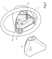
- FIG 1 shows an embodiment according to the invention comprising a steering wheel 1 with a steering wheel hub 2, into which a number of modules 9a, 9b, 12 are to be fitted.
- the steering wheel hub has a lead-through bushing 4 for electrical cables (not shown) for the said modules, and a number of fixing points 3a, 3b, 3c (fixing point 3c is obscured in Figure 1) for a console 5.
- the console 5 comprises an end surface facing the steering wheel hub and provided with a number of notches 6a, 6b, 6c, and having a wall standing essentially at right angles to the end surface around its periphery.
- the said notches 6a, 6b, 6c interact with a corresponding number of fixing elements (not shown) for fitting the console 5 to the fixing points 3a, 3b, 3c.
- the fixing elements that are used for fitting the console 5 in the steering wheel hub 2 also constitute horn switches. The horn can be activated by pressing on the console 5 or on any of its constituent modules. After fitting the modules the electrical wiring will lie protected between the steering wheel hub 2 and the console 5.
- Electrical connection of all constituent modules 9a, 9b 12 can in this case be made either immediately before each module is fitted, by manually joining the electrical contacts together, or automatically when fitting by pushing interacting contacts into one another when each module is pushed into place.
- contacts can preferably be fitted to the console 5 in connection with the positions occupied by the modules.
- the console 5 can also then be connected to the wiring, manually through a notch in the end surface 22a of the console 5 ( Figure 2) or automatically when assembling by means of contacts in the steering wheel hub 2.
- the console 5 has a peripheral wall 22b essentially at right angles to its end surface 22a.
- the console 5 has first guide grooves 7a, 7b for interaction with corresponding first guides 8a, 8b on the sides of a pair of modules 9a, 9b for operating controls facing the console.
- These modules 9a, 9b are positioned and pushed into place with the aid of the said first guide grooves 7a, 7b and guides 8a, 8b, and are locked in position by means of fixing elements 20a, 20b ( Figure 2) in a pair of notches 10a, 10b in the wall 22b of the console 5.
- the modules 9a, 9b are provided with at least one stop 11a, 11b, which comes into contact with the edge of the wall 22b of the console 5 at the same time as the fixing elements 20a, 20b engage in the notches 10a, 10b in the console 5.
- the modules 9a, 9b can be fitted to the console 5 before or after it is fitted to the steering wheel hub 2. Different ways of connecting up the electrical connections (not shown) of the modules 9a, 9b have been described above.
- the modules can also be held in place by further interacting guides and guide grooves of known design, such as opposing U-shaped grooves on the console and tongues on the modules matching the former.
- the aforementioned fixing elements preferably comprise snap fasteners or some other type of quick-coupling.
- both the console 5 and the modules 9a, 9b for operating controls are in addition provided with further, second guide grooves and guides.
- the console 5 is provided with guides in the form of further notches 21a, 21b, in its end surface 22a facing the steering wheel hub 2.
- the modules 9a, 9b have further, second guide grooves 24a, 24b; 25a, 25b in their sides facing the console 5.
- the said second guide grooves 24a, 24b; 25a, 25b are separate from the first guides 8a, 8b, which interact with the console 5 in the assembly direction of the modules.
- An airbag module 12 is provided with guides 13a, 13b and 14a, 14b; 15a, 15b respectively, which interact with corresponding notches 21a, 21b in the console 5 and guide grooves 24a; 24b; 25a, 25b respectively on the modules 9a, 9b for operating controls.
- Figure 3 shows a steering wheel 1 with the console 5 and the modules 9a, 9b for operating controls fitted and ready to receive the airbag module 12.
- the guides 14a, 14b; 15a, 15b Figure 1 engage in the guide grooves 24a, 24b; 25a, 25b on the modules 9a, 9b for operating controls, the airbag module 12 being guided in and centred in relation to both of the said modules 9a, 9b.
- the embodiment according to Figure 1 shows an assembly module with two separate modules for operating controls.
- the design of the steering wheel such as the number of spokes and the number of functions required, it is naturally possible to produce a solution with multiple such modules. It is feasible, for example, to fit four modules in pairs, on a steering wheel according to Figure 1, or to locate one module on each steering wheel spoke of a steering wheel with two or more spokes.
- the determining feature of the invention is that all modules for operating controls are fitted around the periphery of the console, the centring and fitting of the modules in relation to the steering wheel being guided in by means of interacting guides and guide grooves when fitting the airbag module.
Landscapes
- Engineering & Computer Science (AREA)
- Mechanical Engineering (AREA)
- Physics & Mathematics (AREA)
- Acoustics & Sound (AREA)
- Chemical & Material Sciences (AREA)
- Combustion & Propulsion (AREA)
- Transportation (AREA)
- Air Bags (AREA)
- Steering Controls (AREA)
Applications Claiming Priority (2)
| Application Number | Priority Date | Filing Date | Title |
|---|---|---|---|
| SE0026625 | 2000-07-14 | ||
| SE0002662A SE517015C2 (sv) | 2000-07-14 | 2000-07-14 | Monteringsmodul avsedd för en ratt i ett fordon samt förfarande för dess montering |
Publications (3)
| Publication Number | Publication Date |
|---|---|
| EP1172256A2 true EP1172256A2 (fr) | 2002-01-16 |
| EP1172256A3 EP1172256A3 (fr) | 2003-08-13 |
| EP1172256B1 EP1172256B1 (fr) | 2005-09-21 |
Family
ID=20280492
Family Applications (1)
| Application Number | Title | Priority Date | Filing Date |
|---|---|---|---|
| EP01850117A Expired - Lifetime EP1172256B1 (fr) | 2000-07-14 | 2001-07-03 | Module à coussin gonflable et procédé de son assemblage |
Country Status (3)
| Country | Link |
|---|---|
| US (1) | US6592142B2 (fr) |
| EP (1) | EP1172256B1 (fr) |
| SE (1) | SE517015C2 (fr) |
Cited By (2)
| Publication number | Priority date | Publication date | Assignee | Title |
|---|---|---|---|---|
| EP1415870A1 (fr) * | 2002-10-30 | 2004-05-06 | TRW Automotive Safety Systems GmbH | Volant |
| EP1454800A1 (fr) * | 2003-03-03 | 2004-09-08 | TRW Automotive Safety Systems GmbH | Support de générateur de gaz pour un module de coussin gonflable pour le conducteur et module fonctionnel pour un volant d'un véhicule à moteur |
Families Citing this family (7)
| Publication number | Priority date | Publication date | Assignee | Title |
|---|---|---|---|---|
| JP4249921B2 (ja) * | 2001-11-12 | 2009-04-08 | 矢崎総業株式会社 | ステアリングコラムモジュール |
| US7004497B2 (en) * | 2003-01-07 | 2006-02-28 | General Motors Corporation | Styling flexible driver air bag module and method of making same |
| DE102004022634A1 (de) * | 2004-05-07 | 2005-12-15 | Dr.Ing.H.C. F. Porsche Ag | Abdeckungen für ein Lenkrad |
| US8661936B2 (en) * | 2006-01-31 | 2014-03-04 | Toyoda Gosei Co. Ltd. | Trim plate for steering wheel |
| US8912456B2 (en) * | 2007-05-16 | 2014-12-16 | Honeywell International Inc. | ATV switch actuator and housing design |
| JP6096052B2 (ja) * | 2013-05-24 | 2017-03-15 | 日本プラスト株式会社 | ステアリング装置 |
| US9545877B2 (en) * | 2015-02-03 | 2017-01-17 | Ford Global Technologies, Llc | Steering wheel bezel with integrated horn switch function |
Family Cites Families (23)
| Publication number | Priority date | Publication date | Assignee | Title |
|---|---|---|---|---|
| US4325568A (en) * | 1980-07-28 | 1982-04-20 | General Motors Corporation | Modular occupant restraint system |
| JPS59164265A (ja) * | 1983-03-09 | 1984-09-17 | Nippon Plast Co Ltd | 車輌用部品の取付装置 |
| US4590340A (en) * | 1985-01-29 | 1986-05-20 | Nihon Plast Co., Ltd. | Steering wheel assembly for vehicles |
| DE3619937A1 (de) * | 1986-06-13 | 1987-12-17 | Bayerische Motoren Werke Ag | Sicherheits-luftkissen |
| US4804857A (en) * | 1986-11-28 | 1989-02-14 | Toyoda Gosei Co., Ltd. | Relay mechanism for a steering wheel |
| JPH0785990B2 (ja) * | 1988-12-23 | 1995-09-20 | 日産自動車株式会社 | ステアリングホイール |
| JPH02249741A (ja) | 1989-03-24 | 1990-10-05 | Mazda Motor Corp | 自動車のエアバック装置 |
| US5310218A (en) * | 1990-11-27 | 1994-05-10 | Mazda Motor Corporation | Steering wheel structure for vehicle |
| JPH0680083A (ja) * | 1992-09-01 | 1994-03-22 | Suzuki Motor Corp | ステアリングホィール |
| JPH06312664A (ja) * | 1993-04-28 | 1994-11-08 | Toyoda Gosei Co Ltd | ステアリングホイールのパッド |
| US5380037A (en) * | 1993-10-25 | 1995-01-10 | General Motors Corporation | Snap-in inflatable restraint module mounting mechanism including latch elements |
| US5333897A (en) * | 1993-10-25 | 1994-08-02 | General Motors Corporation | Snap lock pin inflatable restraint module mounting mechanism |
| US5403981A (en) * | 1994-01-27 | 1995-04-04 | Chrysler Corporation | Steering wheel including speed control switch and its mounting |
| US5508482A (en) * | 1994-10-11 | 1996-04-16 | General Motors Corporation | Horn activation and steering wheel assembly |
| US5542694A (en) | 1995-05-26 | 1996-08-06 | Larry J. Winget | Thermoplastic air bag cover having a unitary multifunctional domed switching module |
| US5678849A (en) | 1995-05-26 | 1997-10-21 | Larry J. Winget | Thermoplastic air bag cover having a domed front panel and multifunctional unitary switching module |
| JPH0924840A (ja) * | 1995-07-11 | 1997-01-28 | Nippon Plast Co Ltd | ステアリングホイール |
| ID17166A (id) * | 1996-06-07 | 1997-12-04 | Toyo Denso Kk | Struktur pemasangan sakelar |
| JPH107002A (ja) * | 1996-06-18 | 1998-01-13 | Toyoda Gosei Co Ltd | ステアリングホイール |
| JP3734110B2 (ja) * | 1996-06-21 | 2006-01-11 | 矢崎総業株式会社 | ステアリングモジュール |
| US5947509A (en) * | 1996-09-24 | 1999-09-07 | Autoliv Asp, Inc. | Airbag inflator with snap-on mounting attachment |
| JP3440823B2 (ja) * | 1998-05-18 | 2003-08-25 | タカタ株式会社 | エアバッグ装置 |
| DE29918483U1 (de) * | 1999-10-21 | 2000-03-02 | TRW Automotive Safety Systems GmbH & Co. KG, 63743 Aschaffenburg | Fahrzeuglenkrad |
-
2000
- 2000-07-14 SE SE0002662A patent/SE517015C2/sv not_active IP Right Cessation
-
2001
- 2001-07-03 EP EP01850117A patent/EP1172256B1/fr not_active Expired - Lifetime
- 2001-07-13 US US09/682,047 patent/US6592142B2/en not_active Expired - Lifetime
Cited By (3)
| Publication number | Priority date | Publication date | Assignee | Title |
|---|---|---|---|---|
| EP1415870A1 (fr) * | 2002-10-30 | 2004-05-06 | TRW Automotive Safety Systems GmbH | Volant |
| US7111868B2 (en) | 2002-10-30 | 2006-09-26 | Trw Automotive Safety Systems Gmbh | Steering wheel |
| EP1454800A1 (fr) * | 2003-03-03 | 2004-09-08 | TRW Automotive Safety Systems GmbH | Support de générateur de gaz pour un module de coussin gonflable pour le conducteur et module fonctionnel pour un volant d'un véhicule à moteur |
Also Published As
| Publication number | Publication date |
|---|---|
| EP1172256B1 (fr) | 2005-09-21 |
| SE0002662D0 (sv) | 2000-07-14 |
| EP1172256A3 (fr) | 2003-08-13 |
| SE0002662L (sv) | 2002-01-15 |
| US6592142B2 (en) | 2003-07-15 |
| US20020027343A1 (en) | 2002-03-07 |
| SE517015C2 (sv) | 2002-04-02 |
Similar Documents
| Publication | Publication Date | Title |
|---|---|---|
| US6082758A (en) | Driver air bag horn ground spring | |
| US5683259A (en) | Rotary connector | |
| US5002306A (en) | Steering wheel | |
| EP1172256B1 (fr) | Module à coussin gonflable et procédé de son assemblage | |
| EP1493622B1 (fr) | Interrupteur d'avertisseur sonore et systéme de sac gonflable | |
| US7685906B2 (en) | Vehicle steering wheel | |
| WO2013070905A1 (fr) | Ensemble module de coussin de sécurité gonflable de conducteur à encliquetage | |
| WO1998015431A1 (fr) | Module encliquetable pour contacteurs d'avertisseurs et airbag | |
| US5866862A (en) | Vehicle positioning control | |
| GB2394604A (en) | Steering wheel rotary connector | |
| US5797622A (en) | Snap-on steering wheel with integral airbag housing | |
| WO1998014352A1 (fr) | Ensemble sac gonflable et procede de montage | |
| US6151980A (en) | Steering module | |
| EP1056166B1 (fr) | Connecteur rotatif | |
| US20010052694A1 (en) | Multifunctional steering wheel | |
| EP1353826B1 (fr) | Module de coussin gonflable avec contacteur d'avertisseur sonore | |
| EP3604035A1 (fr) | Ensemble de connexion électrique, dispositif d'éclairage automobile et procédé de fabrication d'un dispositif d'éclairage automobile | |
| EP2390143B1 (fr) | Agencement de connexion pour module d'airbag | |
| JPH0930425A (ja) | ステアリングホイール | |
| JP3789284B2 (ja) | 車両のハンドル用スイッチユニット | |
| EP2272720B1 (fr) | Module de direction | |
| KR20030031151A (ko) | 특히 차량용 레인 센서 및 레인 센서의 조립 방법 | |
| JP2004079484A (ja) | 車載用複合操作型電気部品の操作機構 | |
| US5769450A (en) | Steering wheel assembly containing an air bag module | |
| US20210362667A1 (en) | Steering wheel module for vehicle |
Legal Events
| Date | Code | Title | Description |
|---|---|---|---|
| PUAI | Public reference made under article 153(3) epc to a published international application that has entered the european phase |
Free format text: ORIGINAL CODE: 0009012 |
|
| AK | Designated contracting states |
Kind code of ref document: A2 Designated state(s): AT BE CH CY DE DK ES FI FR GB GR IE IT LI LU MC NL PT SE TR |
|
| AX | Request for extension of the european patent |
Free format text: AL;LT;LV;MK;RO;SI |
|
| PUAL | Search report despatched |
Free format text: ORIGINAL CODE: 0009013 |
|
| AK | Designated contracting states |
Designated state(s): AT BE CH CY DE DK ES FI FR GB GR IE IT LI LU MC NL PT SE TR |
|
| AX | Request for extension of the european patent |
Extension state: AL LT LV MK RO SI |
|
| 17P | Request for examination filed |
Effective date: 20040210 |
|
| AKX | Designation fees paid |
Designated state(s): DE FR |
|
| 17Q | First examination report despatched |
Effective date: 20040506 |
|
| RBV | Designated contracting states (corrected) |
Designated state(s): DE FR GB |
|
| RBV | Designated contracting states (corrected) |
Designated state(s): DE GB |
|
| GRAP | Despatch of communication of intention to grant a patent |
Free format text: ORIGINAL CODE: EPIDOSNIGR1 |
|
| GRAS | Grant fee paid |
Free format text: ORIGINAL CODE: EPIDOSNIGR3 |
|
| GRAA | (expected) grant |
Free format text: ORIGINAL CODE: 0009210 |
|
| AK | Designated contracting states |
Kind code of ref document: B1 Designated state(s): DE GB |
|
| REG | Reference to a national code |
Ref country code: GB Ref legal event code: FG4D |
|
| REF | Corresponds to: |
Ref document number: 60113482 Country of ref document: DE Date of ref document: 20051027 Kind code of ref document: P |
|
| REF | Corresponds to: |
Ref document number: 60113482 Country of ref document: DE Date of ref document: 20060202 Kind code of ref document: P |
|
| PLBE | No opposition filed within time limit |
Free format text: ORIGINAL CODE: 0009261 |
|
| STAA | Information on the status of an ep patent application or granted ep patent |
Free format text: STATUS: NO OPPOSITION FILED WITHIN TIME LIMIT |
|
| 26N | No opposition filed |
Effective date: 20060622 |
|
| PGFP | Annual fee paid to national office [announced via postgrant information from national office to epo] |
Ref country code: DE Payment date: 20140714 Year of fee payment: 14 |
|
| PGFP | Annual fee paid to national office [announced via postgrant information from national office to epo] |
Ref country code: GB Payment date: 20140716 Year of fee payment: 14 |
|
| REG | Reference to a national code |
Ref country code: DE Ref legal event code: R119 Ref document number: 60113482 Country of ref document: DE |
|
| GBPC | Gb: european patent ceased through non-payment of renewal fee |
Effective date: 20150703 |
|
| PG25 | Lapsed in a contracting state [announced via postgrant information from national office to epo] |
Ref country code: GB Free format text: LAPSE BECAUSE OF NON-PAYMENT OF DUE FEES Effective date: 20150703 Ref country code: DE Free format text: LAPSE BECAUSE OF NON-PAYMENT OF DUE FEES Effective date: 20160202 |