EP1174164A1 - Container mit Energieversorgung und/oder Klimaanlage - Google Patents
Container mit Energieversorgung und/oder Klimaanlage Download PDFInfo
- Publication number
- EP1174164A1 EP1174164A1 EP01116890A EP01116890A EP1174164A1 EP 1174164 A1 EP1174164 A1 EP 1174164A1 EP 01116890 A EP01116890 A EP 01116890A EP 01116890 A EP01116890 A EP 01116890A EP 1174164 A1 EP1174164 A1 EP 1174164A1
- Authority
- EP
- European Patent Office
- Prior art keywords
- heat
- cooling
- air
- heat transfer
- room
- Prior art date
- Legal status (The legal status is an assumption and is not a legal conclusion. Google has not performed a legal analysis and makes no representation as to the accuracy of the status listed.)
- Granted
Links
- 238000004378 air conditioning Methods 0.000 title claims description 19
- 238000001816 cooling Methods 0.000 claims abstract description 45
- 239000012530 fluid Substances 0.000 claims abstract description 4
- 238000000034 method Methods 0.000 claims abstract description 4
- 230000008569 process Effects 0.000 claims abstract description 4
- 239000003570 air Substances 0.000 claims description 50
- 238000012546 transfer Methods 0.000 claims description 17
- 238000010438 heat treatment Methods 0.000 claims description 10
- 239000012080 ambient air Substances 0.000 claims description 9
- 238000005192 partition Methods 0.000 claims description 8
- 239000000463 material Substances 0.000 claims description 7
- 239000004576 sand Substances 0.000 claims description 5
- 238000004140 cleaning Methods 0.000 claims description 4
- 239000000428 dust Substances 0.000 claims description 4
- 238000009423 ventilation Methods 0.000 claims description 4
- 230000001681 protective effect Effects 0.000 claims description 3
- 239000000126 substance Substances 0.000 claims description 3
- 239000000969 carrier Substances 0.000 claims description 2
- 238000005202 decontamination Methods 0.000 claims description 2
- 230000003588 decontaminative effect Effects 0.000 claims description 2
- 238000000926 separation method Methods 0.000 claims 2
- 238000009825 accumulation Methods 0.000 claims 1
- 239000000446 fuel Substances 0.000 claims 1
- 239000002918 waste heat Substances 0.000 abstract description 13
- 239000002775 capsule Substances 0.000 abstract 1
- 238000002485 combustion reaction Methods 0.000 description 9
- 239000007789 gas Substances 0.000 description 8
- 239000000498 cooling water Substances 0.000 description 7
- 230000008878 coupling Effects 0.000 description 5
- 238000010168 coupling process Methods 0.000 description 5
- 238000005859 coupling reaction Methods 0.000 description 5
- 239000007788 liquid Substances 0.000 description 5
- 239000003507 refrigerant Substances 0.000 description 5
- 238000013461 design Methods 0.000 description 4
- 238000010586 diagram Methods 0.000 description 4
- 239000000243 solution Substances 0.000 description 4
- 239000012267 brine Substances 0.000 description 3
- 238000010276 construction Methods 0.000 description 3
- HPALAKNZSZLMCH-UHFFFAOYSA-M sodium;chloride;hydrate Chemical compound O.[Na+].[Cl-] HPALAKNZSZLMCH-UHFFFAOYSA-M 0.000 description 3
- 230000008901 benefit Effects 0.000 description 2
- 238000007664 blowing Methods 0.000 description 2
- 230000008859 change Effects 0.000 description 2
- 239000011248 coating agent Substances 0.000 description 2
- 238000000576 coating method Methods 0.000 description 2
- 238000005485 electric heating Methods 0.000 description 2
- 230000017525 heat dissipation Effects 0.000 description 2
- 238000009413 insulation Methods 0.000 description 2
- 230000009467 reduction Effects 0.000 description 2
- 230000029058 respiratory gaseous exchange Effects 0.000 description 2
- 239000002351 wastewater Substances 0.000 description 2
- XLYOFNOQVPJJNP-UHFFFAOYSA-N water Substances O XLYOFNOQVPJJNP-UHFFFAOYSA-N 0.000 description 2
- 241001156002 Anthonomus pomorum Species 0.000 description 1
- 239000000443 aerosol Substances 0.000 description 1
- 238000007605 air drying Methods 0.000 description 1
- 239000013043 chemical agent Substances 0.000 description 1
- 238000006243 chemical reaction Methods 0.000 description 1
- 238000009833 condensation Methods 0.000 description 1
- 230000005494 condensation Effects 0.000 description 1
- 238000011109 contamination Methods 0.000 description 1
- PXBRQCKWGAHEHS-UHFFFAOYSA-N dichlorodifluoromethane Chemical compound FC(F)(Cl)Cl PXBRQCKWGAHEHS-UHFFFAOYSA-N 0.000 description 1
- 239000002283 diesel fuel Substances 0.000 description 1
- 230000005611 electricity Effects 0.000 description 1
- 230000002349 favourable effect Effects 0.000 description 1
- 239000002803 fossil fuel Substances 0.000 description 1
- 239000013529 heat transfer fluid Substances 0.000 description 1
- 239000004922 lacquer Substances 0.000 description 1
- 238000012423 maintenance Methods 0.000 description 1
- 238000002156 mixing Methods 0.000 description 1
- 239000000203 mixture Substances 0.000 description 1
- 238000012544 monitoring process Methods 0.000 description 1
- 230000008520 organization Effects 0.000 description 1
- 239000002245 particle Substances 0.000 description 1
- 230000035515 penetration Effects 0.000 description 1
- 230000001172 regenerating effect Effects 0.000 description 1
- 230000004044 response Effects 0.000 description 1
- 239000002689 soil Substances 0.000 description 1
- 239000002904 solvent Substances 0.000 description 1
- 239000013589 supplement Substances 0.000 description 1
- 230000004083 survival effect Effects 0.000 description 1
Images




Classifications
-
- F—MECHANICAL ENGINEERING; LIGHTING; HEATING; WEAPONS; BLASTING
- F24—HEATING; RANGES; VENTILATING
- F24F—AIR-CONDITIONING; AIR-HUMIDIFICATION; VENTILATION; USE OF AIR CURRENTS FOR SCREENING
- F24F3/00—Air-conditioning systems in which conditioned primary air is supplied from one or more central stations to distributing units in the rooms or spaces where it may receive secondary treatment; Apparatus specially designed for such systems
-
- F—MECHANICAL ENGINEERING; LIGHTING; HEATING; WEAPONS; BLASTING
- F24—HEATING; RANGES; VENTILATING
- F24F—AIR-CONDITIONING; AIR-HUMIDIFICATION; VENTILATION; USE OF AIR CURRENTS FOR SCREENING
- F24F2221/00—Details or features not otherwise provided for
- F24F2221/44—Protection from terrorism or theft
-
- F—MECHANICAL ENGINEERING; LIGHTING; HEATING; WEAPONS; BLASTING
- F25—REFRIGERATION OR COOLING; COMBINED HEATING AND REFRIGERATION SYSTEMS; HEAT PUMP SYSTEMS; MANUFACTURE OR STORAGE OF ICE; LIQUEFACTION SOLIDIFICATION OF GASES
- F25B—REFRIGERATION MACHINES, PLANTS OR SYSTEMS; COMBINED HEATING AND REFRIGERATION SYSTEMS; HEAT PUMP SYSTEMS
- F25B27/00—Machines, plants or systems, using particular sources of energy
-
- F—MECHANICAL ENGINEERING; LIGHTING; HEATING; WEAPONS; BLASTING
- F25—REFRIGERATION OR COOLING; COMBINED HEATING AND REFRIGERATION SYSTEMS; HEAT PUMP SYSTEMS; MANUFACTURE OR STORAGE OF ICE; LIQUEFACTION SOLIDIFICATION OF GASES
- F25D—REFRIGERATORS; COLD ROOMS; ICE-BOXES; COOLING OR FREEZING APPARATUS NOT OTHERWISE PROVIDED FOR
- F25D11/00—Self-contained movable devices, e.g. domestic refrigerators
- F25D11/003—Transport containers
Definitions
- the invention relates to the energy supply and / or air conditioning of mobile Workrooms.
- the energy supply is for larger ones Container groups through a (also containerized) diesel generator set.
- Functionally individually used containers must be used for self-sufficient energy supply and / or air conditioning with a power and cooling or heating requirement Primary energy converters.
- Standardized diesel generator sets (SEA) and introduced air conditioning systems (in partial air conditioners) of different performance levels are part of the fixed one Part of the military equipment.
- the SEAs are based on one or two axes Trailer or next to the container loaded directly on the platform of the truck.
- the air conditioning system with fresh air admixture connected to a power supplier must be, according to the prior art on the outside of an end wall attached to the container or inside it, usually a so-called technical room, arranged. This space is separated from the working space of the container equipped with air inlet and outlet openings.
- the task to be solved with the invention is that for the electrical Power supply and / or air conditioning of mobile work rooms necessary procedural Arrange components so that only the components have a partial surface to the outside air, which for the energy and air exchange with the Environment are physically imperative.
- the system components for energy provision (energy conversion), Heating and cooling arranged in a hermetically sealed room, preferably a part of the container technical room or plant housing (in the case of a freestanding or attached to the outside of the container for a system that can only be loaded).
- a hermetically sealed room preferably a part of the container technical room or plant housing (in the case of a freestanding or attached to the outside of the container for a system that can only be loaded).
- the Inner walls of the cooling room are gap-free and for residue-free cleaning designed with hot liquids and chemicals.
- the wastewater is on Soil collected.
- the temperature levels of the waste heat differ.
- the Engine cooling water around 115 ° C is common.
- the same temperature can, if appropriate Insulation class can be achieved in the generator.
- the temperature of the heat transfer medium are only a few degrees above the ambient temperature.
- the limit is around 7 to 8 kW mech., It is in the available from known container designs for the technical room Space according to the invention constructively possible, part of the outer wall of the Train the machine room as a heat exchanger. This is on the inside flowed through by cooling water, on the outside by the cooling air (ambient air) blown.
- the conceptually most consistent solution with minimal adjustment effort Commercially available and militarily imported devices, the arrangement of Intermediate circuits with liquid heat transfer medium (and circulation pump) between the Heat sources of energy supply and air conditioning and the external, as required dimensioned liquid-air heat exchangers.
- the heat feed in the intermediate circuits with an adjusted temperature level is carried out by means of compact plate heat exchangers.
- the heat transfer fluid consists of a Water-antifreeze mixture with one of the minimum operating and storage temperature corresponding mixing percentage. To compensate for the thermal Expansion vessels serve to maintain a certain amount of fluid serve the small possible with the opening of the quick couplings To cover fluid loss.
- That a brine intermediate circuit also on the evaporator side for room and device cooling, can be useful in addition to the modular structure still from the advantage that by interconnecting the two brine circuits high waste heat in the container this waste heat at low to medium Ambient temperatures without operating the cooling system directly to the environment can be dissipated.
- the outside part, through which ambient air flows, with heat exchangers and blower (s), which is hermetically separated from the inner part of the plant can be a compartment of the Technical room (system housing) with air inlet and outlet grilles or as Detachable insert into the partially open structure of the technical room or SEA housing be used.
- a contaminated cooling unit can also limited space as an independent unit and in operation in a few meters from the container. In particular, this can then become necessary if an arrangement due to high performance requirements the cooling room next to the technical room is no longer possible.
- the The cooling unit, which has to be loaded separately, is then for the operation, which is no longer mobile is possible with at least 4 liquid lines, the power cable and possibly one Connect the control line to the container (or the SEA block).
- the spatial division is independent of the construction and size of the container in work room 1, machine room 2 and cooling room 4, Fig. 1.
- the block diagram this figure corresponds to a basic equipment of self-sufficient energy supply and Air conditioning.
- the main subsystems / components for this are the fresh air supply 21 with inlet filter 22 and blower 23, internal combustion engine 24 with coupled Generator 25, exhaust gas discharge 26 and pump-driven cooling water circuit 27, refrigerant circuit with compressor and control 28 and control cabinet with cooling 29.
- Fresh air 21, electricity 11 and refrigerant 12 are in the work area out, in which the evaporator with circulating air fan 13 on the wall or on the Ceiling are arranged.
- the heat exchangers 41 and 42 which correspond to the heat transfer medium Quick couplings 43 and 44 with the motor / generator cooling circuit 27 and Refrigerant circuit 30 are connected, the engine / generator waste heat of the cooling water 31 or as a condenser, the waste heat from the work area 1.
- the fresh air circulation causes the fan (s) 45 with inlet filter 46 and outlet grille 47 If there are 2 fans, differentiated control is possible.
- the finned structure of the heat exchangers 41 and 42 and their arrangement in the cooling space 4 is dimensioned in addition to the correct choice of material so that a blow off with compressed air or solvent (sand, dust, aerosol particles) to no damage leads.
- the exchange of the heat exchanger is done by loosening the attachment and Disconnect the quick couplings 43, 44 possible. Appropriate measures apply for the blower motor unit.
- the inside surface of the cooling room is smooth, with appropriate material resistance (through choice of material or decontaminable Lacquer coating). The waste water from the cleaning process is discharged to the floor.
- FIG ABC protective ventilation system 32 expanded, the 23 with the fan switched off Working room 1 supplied with filtered fresh air.
- the heat exchangers 41 and 42 which are also here of the heat carriers 30 and 31 flowed through directly are here as fixed in the partition 33 between machine and cooling room 2, 4 installed heat transfer points.
- FIG. 3 The block diagram of the components in machine room 2 was starting in Fig. 3 of which in FIG. 1 is expanded by an air heater 34 heated with diesel fuel. Fresh air inlet 21 and exhaust gas outlet 26 are additionally with this inlet air and the exhaust gas.
- the heat transfer media 30 and 31 act here on intermediate heat transfer circuits 35 and 36 by means of the plate heat exchangers 37 and 38. This turns them into diesel generators and cooling unit in almost commercial design, 24, 25, 28, Installed.
- the brine intermediate circuits 35 and 36 become through the partition 32 Heat exchangers 41 and 42 performed in the cooling room 4.
- waste heat from the internal combustion engine can be subjected to a further cooling water Heat exchanger to heat the circulating air flow 14 or in Supplement or instead of the electric heating a hot water heating circuit heat.
- EMC-tightness is the advantage of the present concept, in that for the Cooling room 4 none and only for the machine room 2 complex Measures for the surface coating and the few cable and pipe penetrations must be taken. Constructive precautions Doors and openings (EMC door seals and honeycomb chimneys) are eliminated.
- FIG. 4 A simple constructive embodiment of the heat dissipation from the machine room 2 in the cooling space 4 and to the environment is shown in FIG. 4.
- This solution as Cold plate 51 through which the heat transfer medium is exposed to ambient air Ribbing 52 is preferably suitable for smaller performances. These can be both from a low energy requirement of the container (devices and air conditioning) as well as from a significantly improved thermal insulation of the container walls result.
- the heat exchanger 50 with the inlet and outlet 53 and 54 is heat, air and EMC-tight used in the partition 32.
- FIG 6 shows the container part 60, the machine and cooling room 2 and 4 receives.
- the machine room 2 is for monitoring and maintenance work through the door 61 accessible.
- the air inlet and outlet cross sections 21, 46 and 47 are, for example in the long wall.
- the cooling space 4 can be opened with the door 62, if necessary, even after separating the various quick couplings as a whole from the Containers are pulled out.
- An arrangement can also be useful here be that the cooling space is horizontal, over part or all of the width of the Containers, above the engine room. The air entry is then expedient on the front, blowing out upwards.
- each cooling circuit can also be done as a separate one Block run.
Landscapes
- Engineering & Computer Science (AREA)
- Chemical & Material Sciences (AREA)
- Combustion & Propulsion (AREA)
- Mechanical Engineering (AREA)
- General Engineering & Computer Science (AREA)
- Other Air-Conditioning Systems (AREA)
- Central Heating Systems (AREA)
- Physical Or Chemical Processes And Apparatus (AREA)
Abstract
Description
- Frischluft/Abluft zur Belüftung des personenbesetzten Container-Innenraums. Im Falle von hohen Luftwechselzahlen, wie z. B. als Operationsraum oder Intensivstation ausgerüstete Container, empfiehlt sich zur Senkung des Energiebedarfs beim Heizen und Kühlen die Anordnung eines regenerativen Wärmetauschers.
- Verbrennungsluft/Abgas und Kühlluft für den Verbrennungsmotor (luft- oder wassergekühlt).
- Die Klimatisierung ist bis auf den beigemischten, meist geringen Frischluftanteil, ein Erwärmen oder Kühlen der Container-Umluft. Ein weiterer Bedarf an Außenluft ergibt sich zum Betreiben des Brenners im Falle einer Öl- oder Gasluftheizung, nicht beim elektrischen Heizen. Beim Kühlen (Kompressor mit Kältemittelkreis) muß die Raum- und Prozeßabwärme vom Kondensator an die Umgebung abgeführt werden.
- Die Lufttrocknung/-befeuchtung, Bestandteil einer Vollklimaanlage, bleiben qualitativ ohne Einfluß auf den beschriebenen Luftaustausch.
- Fig. 1
- das Blockschema der Aggregate und Komponenten in einer Anordnung mit der direkten Durchführung des Motor- und Generatorkühlwassers sowie des Kältemittels zu den Wärmetauschern im Kühlraum,
- Fig. 2
- das Blockschema nach Fig. 1 mit ABC-Schutzbelüftung in einer Anordnung mit in der Trennwand zwischen Maschinen- und Kühlraum eingelassenen Wärmetauschern,
- Fig. 3
- das Blockschema nach Fig. 1 mit Ölluftheizung in einer Anordnung mit einem Wärmetauscher-Zwischenkreis im Maschinenraum und Wärmetauschern im Kühlungsraum,
- Fig. 4
- die konstruktive Ausführung eines Wärmetauschers in der Trennwand mit luftseitigen Kühlrippen,
- Fig. 5
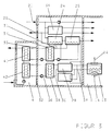
- einen Wärmetauscher der gleichen Funktion wie nach Fig. 4 mit Unterstützung des Wärmetransports durch Wärmeleitrohre,
- Fig. 6
- die perspektivische Ansicht eines Containers mit Luftein- und -austrittsgitter in der Türe des Kühlungsraumes.
Claims (8)
- Energieversorgung und/oder Klimaanlage für mobile Arbeitsräume, angeordnet in einem Teilraum des Containers oder in einem Gehäuse, bestehend aus Diesel-Generator-Aggregat, Voll- oder Teilklimaanlage, Frischluftversorgung und Steuerung, erforderlichenfalls mit den Zubehörkomponenten Brennstoffheizung, ABC-Schutzbelüftung, Fremdnetzeinspeisung und -versorgung dadurch gekennzeichnet, dass der Raum für die genannten Teileinheiten dicht gekapselt ist und die Verlustwärmen auf einem dem thermischen Prozeß der Teileinheit entsprechenden Temperaturniveau mittels eines fluiden Wärmeträgers in einen von der Umgebungsluft zwangsweise durchströmten Raum herausgeführt werden.
- Anlage nach Anspruch 1, dadurch gekennzeichnet, dass die Wärmeträger aus dem Maschinenraum durch geschirmte Rohrleitungen zu den Wärmetauschern im Kühlungsraum geführt werden.
- Anlage nach Anspruch 1, dadurch gekennzeichnet, dass Wärmetauscher in der Trennwand zwischen Maschinen- und Kühlungsraum eingesetzt sind, die auf der einen Seite von dem fluiden Wärmeträger, auf der anderen Seite von der Umgebungsluft beaufschlagt sind, wobei der Wärmeübergang dazwischen durch Wärmeleitung in Wärmetauschermaterial erfolgt.
- Anlage nach Ansprüchen 1 und 3, dadurch gekennzeichnet, dass der Wärmetransport durch Wärmeleitrohre in der Trennwand zwischen den von den Wärmeträgern durchströmten Kammern unterstützt wird.
- Anlage nach Ansprüchen 1 bis 4, dadurch gekennzeichnet, dass mittels Wärmeträger-Zwischenkreise eine Trennung zwischen dem Kreis des Wärmeanfalls und dem in den Kühlungsraum geführten Wärmeträgerkreis besteht.
- Anlage nach Ansprüchen 1, 3 und 4, dadurch gekennzeichnet, dass die an die Umgebungsluft Wärme abgebenden Oberflächen sowie die Innenoberflächen des Kühlungsraumes unter Vermeidung enger Spalte und unzugänglicher Oberflächen so dimensioniert sind, daß mit Feldmitteln eine rasche Säuberung und Dekontamination von ABC-Chemikalien, Sand und Staub möglich ist.
- Anlage nach Ansprüchen 1 bis 4 und 6, dadurch gekennzeichnet, dass der Kühlungsraum als Ganzes mit Gebläse(n) und ggf. Wärmetauschern nach Trennung der Wärmeträgerleitungen aus dem Container oder SEA-Gehäuse entnommen werden kann.
- Anlage nach Ansprüchen 1 bis 4, 6 und 7, dadurch gekennzeichnet, dass der Kühlungsraum als eine oder den einzelnen Kühlkreisen zugeordnete, getrennt verlastbare Baueinheit ausgebildet ist.
Applications Claiming Priority (2)
| Application Number | Priority Date | Filing Date | Title |
|---|---|---|---|
| DE10035563 | 2000-07-21 | ||
| DE10035563A DE10035563C2 (de) | 2000-07-21 | 2000-07-21 | Mobiler Container |
Publications (2)
| Publication Number | Publication Date |
|---|---|
| EP1174164A1 true EP1174164A1 (de) | 2002-01-23 |
| EP1174164B1 EP1174164B1 (de) | 2004-12-15 |
Family
ID=7649753
Family Applications (1)
| Application Number | Title | Priority Date | Filing Date |
|---|---|---|---|
| EP01116890A Expired - Lifetime EP1174164B1 (de) | 2000-07-21 | 2001-07-11 | Container mit Energieversorgung und/oder Klimaanlage |
Country Status (3)
| Country | Link |
|---|---|
| EP (1) | EP1174164B1 (de) |
| AT (1) | ATE284734T1 (de) |
| DE (2) | DE10035563C2 (de) |
Cited By (3)
| Publication number | Priority date | Publication date | Assignee | Title |
|---|---|---|---|---|
| EP1517099A1 (de) * | 2003-09-20 | 2005-03-23 | EADS Deutschland GmbH | Klimatisierter mobiler Container |
| WO2010105645A1 (de) * | 2009-03-19 | 2010-09-23 | Hess-Wohnwerk Gmbh & Co. Kg | Vorrichtung zum verkleben von verbindungsteilen |
| CN118371044A (zh) * | 2024-06-25 | 2024-07-23 | 江苏睿济鼎洲科技工程有限公司 | 一种水处理用的防积沙管道 |
Families Citing this family (3)
| Publication number | Priority date | Publication date | Assignee | Title |
|---|---|---|---|---|
| DE10345914B4 (de) * | 2003-09-26 | 2006-05-18 | Ulf Deisenroth | Modulares Schutzraumsystem, insbesondere zum Transport von Personen und/oder Gegenständen |
| DE20315057U1 (de) | 2003-09-26 | 2005-02-10 | Deisenroth, Ulf | Modulares Schutzraumsystem, insbesondere zum Transport von Personen und/oder Gegenständen |
| DE102010010346A1 (de) * | 2010-03-05 | 2011-09-08 | Dynatronic Gmbh | Verfahren und Vorrichtung zur Stromversorgung von elektrischen Komponenten in geschlossenem Gehäuse |
Citations (6)
| Publication number | Priority date | Publication date | Assignee | Title |
|---|---|---|---|---|
| US3191517A (en) * | 1961-10-27 | 1965-06-29 | Isel I Solzman | Ventilating system for fallout shelter |
| CH577833A5 (en) * | 1974-06-21 | 1976-07-30 | Sveadiesel Ab | Insulated chamber for dust laden atmosphere - has filtered air circulated between double walls, cabin cooled and vibration damped |
| EP0064892A1 (de) * | 1981-04-30 | 1982-11-17 | Société de Services Généraux et de Gestion d'Entreprise de Bâtiments de Travaux Publics ou Ind.: S.G.G.- B.T.P.I., S.à.r.l. | Einrichtung für nuklearen, biologischen und chemischen Schutz einer Tiefgarage |
| DE3726114A1 (de) * | 1987-08-06 | 1989-02-16 | Hans Dipl Ing Bong | Verschlusselement in verbindung mit einer lueftungsanlage und luftaufbereitungsanlage zur reinigung von kontaminierten aussenluftvolumenstroemen |
| EP0542707A1 (de) * | 1991-11-15 | 1993-05-19 | AB Ventilatorverken | Ventilationsmethode für Zelte oder dergleichen und Vorrichtung dafür |
| DE4328810A1 (de) * | 1993-08-27 | 1995-03-02 | Weiss Umwelttechnik Gmbh | Shelter |
Family Cites Families (4)
| Publication number | Priority date | Publication date | Assignee | Title |
|---|---|---|---|---|
| DE2625449B2 (de) * | 1976-06-05 | 1979-04-12 | Matsushita Seiko Co., Ltd., Osaka (Japan) | Anlage zum Temperieren von Räumen mit einer Innenraum-Einheit und einem den Kondensator enthaltenden Außengerät |
| DE3406628A1 (de) * | 1984-02-23 | 1985-09-12 | Siemens AG, 1000 Berlin und 8000 München | Einrichtung zum schutz eines insbesondere an einem shelter befestigten klimageraetes |
| DE3924455A1 (de) * | 1989-07-24 | 1991-01-31 | Kufler & Hross Gmbh & Co Kg | Modulares sonderklima-raumsystem |
| DE29918368U1 (de) * | 1999-10-19 | 2000-01-13 | M. Schall GmbH + Co. KG., 52399 Merzenich | Begehbares Gehäuse insbesondere in Containerform |
-
2000
- 2000-07-21 DE DE10035563A patent/DE10035563C2/de not_active Expired - Fee Related
-
2001
- 2001-07-11 AT AT01116890T patent/ATE284734T1/de not_active IP Right Cessation
- 2001-07-11 EP EP01116890A patent/EP1174164B1/de not_active Expired - Lifetime
- 2001-07-11 DE DE50104810T patent/DE50104810D1/de not_active Expired - Fee Related
Patent Citations (6)
| Publication number | Priority date | Publication date | Assignee | Title |
|---|---|---|---|---|
| US3191517A (en) * | 1961-10-27 | 1965-06-29 | Isel I Solzman | Ventilating system for fallout shelter |
| CH577833A5 (en) * | 1974-06-21 | 1976-07-30 | Sveadiesel Ab | Insulated chamber for dust laden atmosphere - has filtered air circulated between double walls, cabin cooled and vibration damped |
| EP0064892A1 (de) * | 1981-04-30 | 1982-11-17 | Société de Services Généraux et de Gestion d'Entreprise de Bâtiments de Travaux Publics ou Ind.: S.G.G.- B.T.P.I., S.à.r.l. | Einrichtung für nuklearen, biologischen und chemischen Schutz einer Tiefgarage |
| DE3726114A1 (de) * | 1987-08-06 | 1989-02-16 | Hans Dipl Ing Bong | Verschlusselement in verbindung mit einer lueftungsanlage und luftaufbereitungsanlage zur reinigung von kontaminierten aussenluftvolumenstroemen |
| EP0542707A1 (de) * | 1991-11-15 | 1993-05-19 | AB Ventilatorverken | Ventilationsmethode für Zelte oder dergleichen und Vorrichtung dafür |
| DE4328810A1 (de) * | 1993-08-27 | 1995-03-02 | Weiss Umwelttechnik Gmbh | Shelter |
Cited By (3)
| Publication number | Priority date | Publication date | Assignee | Title |
|---|---|---|---|---|
| EP1517099A1 (de) * | 2003-09-20 | 2005-03-23 | EADS Deutschland GmbH | Klimatisierter mobiler Container |
| WO2010105645A1 (de) * | 2009-03-19 | 2010-09-23 | Hess-Wohnwerk Gmbh & Co. Kg | Vorrichtung zum verkleben von verbindungsteilen |
| CN118371044A (zh) * | 2024-06-25 | 2024-07-23 | 江苏睿济鼎洲科技工程有限公司 | 一种水处理用的防积沙管道 |
Also Published As
| Publication number | Publication date |
|---|---|
| DE50104810D1 (de) | 2005-01-20 |
| DE10035563A1 (de) | 2002-02-07 |
| ATE284734T1 (de) | 2005-01-15 |
| DE10035563C2 (de) | 2002-08-01 |
| EP1174164B1 (de) | 2004-12-15 |
Similar Documents
| Publication | Publication Date | Title |
|---|---|---|
| EP1319536B1 (de) | Klimatisierungseinrichtung für ein Fahrzeug | |
| DE10008383A1 (de) | Schaltschrank oder Gehäuse mit einer Klimatisierungseinrichtung | |
| EP1207732A2 (de) | Schaltschrank mit einer Klimatisierungseinrichtung | |
| DE4104423C2 (de) | Entlüftungs- und Belüftungsanlage mit einem Wärmespeicher | |
| EP0842382B1 (de) | H-thermokompaktgerät | |
| DE202019100059U1 (de) | Inverteranordnung | |
| EP2524172B1 (de) | Wärmeübertrageranordnung | |
| EP0085411B1 (de) | Heiz- bzw. Kühleinrichtung | |
| EP1174164B1 (de) | Container mit Energieversorgung und/oder Klimaanlage | |
| DE102008016577A1 (de) | Wärmepumpeneinrichtung | |
| CH708202A2 (de) | Lüftungsanlage. | |
| DE102010062647A1 (de) | Schienenfahrzeug mit einem zur Kühlung von elektrischen Vorrichtungen vorgesehenen Klimatisierungssystem sowie Verfahren zum Kühlen der elektrischen Vorrichtungen in dem Schienenfahrzeug | |
| EP2337696A1 (de) | Klimatisierungsanordnung | |
| CN114178028A (zh) | 一种可控型的建筑施工拆迁用砖瓦破碎机及其使用方法 | |
| EP1517099B1 (de) | Klimatisierter mobiler Container | |
| DE20101676U1 (de) | Klimagerät zur Luftbehandlung eines Raumes | |
| EP0632192A1 (de) | Lufteinlasskanal für einen Gasturbinensatz | |
| DE3333828A1 (de) | Energieversorgungsanlage | |
| EP3124883A1 (de) | Luftkonditionierung für eine gebäudeetage | |
| DE202004003443U1 (de) | Kanallose Lüftungsanlage mittels induktiver Luftdurchmischung | |
| EP1093199A1 (de) | Elektrische Schaltanlage | |
| EP3356167A2 (de) | Klimaanlage und motorkühlung für fahrzuege mittels abgas | |
| DE4111896A1 (de) | Kuehldecke | |
| DE102007063314A1 (de) | Vorrichtung zur Stromerzeugung | |
| DE202025003452U1 (de) | System zur Vor-Ort-Erzeugung von Druckluft und Sauerstoff aus Umgebungsluft |
Legal Events
| Date | Code | Title | Description |
|---|---|---|---|
| PUAI | Public reference made under article 153(3) epc to a published international application that has entered the european phase |
Free format text: ORIGINAL CODE: 0009012 |
|
| AK | Designated contracting states |
Kind code of ref document: A1 Designated state(s): AT BE CH CY DE DK ES FI FR GB GR IE IT LI LU MC NL PT SE TR |
|
| AX | Request for extension of the european patent |
Free format text: AL;LT;LV;MK;RO;SI |
|
| 17P | Request for examination filed |
Effective date: 20020418 |
|
| AKX | Designation fees paid |
Free format text: AT BE CH CY DE DK ES FI FR GB GR IE IT LI LU MC NL PT SE TR |
|
| 17Q | First examination report despatched |
Effective date: 20040406 |
|
| GRAP | Despatch of communication of intention to grant a patent |
Free format text: ORIGINAL CODE: EPIDOSNIGR1 |
|
| GRAS | Grant fee paid |
Free format text: ORIGINAL CODE: EPIDOSNIGR3 |
|
| RAP1 | Party data changed (applicant data changed or rights of an application transferred) |
Owner name: EADS DEUTSCHLAND GMBH |
|
| GRAA | (expected) grant |
Free format text: ORIGINAL CODE: 0009210 |
|
| AK | Designated contracting states |
Kind code of ref document: B1 Designated state(s): AT BE CH CY DE DK ES FI FR GB GR IE IT LI LU MC NL PT SE TR |
|
| PG25 | Lapsed in a contracting state [announced via postgrant information from national office to epo] |
Ref country code: IT Free format text: LAPSE BECAUSE OF FAILURE TO SUBMIT A TRANSLATION OF THE DESCRIPTION OR TO PAY THE FEE WITHIN THE PRESCRIBED TIME-LIMIT;WARNING: LAPSES OF ITALIAN PATENTS WITH EFFECTIVE DATE BEFORE 2007 MAY HAVE OCCURRED AT ANY TIME BEFORE 2007. THE CORRECT EFFECTIVE DATE MAY BE DIFFERENT FROM THE ONE RECORDED. Effective date: 20041215 Ref country code: TR Free format text: LAPSE BECAUSE OF FAILURE TO SUBMIT A TRANSLATION OF THE DESCRIPTION OR TO PAY THE FEE WITHIN THE PRESCRIBED TIME-LIMIT Effective date: 20041215 Ref country code: ES Free format text: LAPSE BECAUSE OF FAILURE TO SUBMIT A TRANSLATION OF THE DESCRIPTION OR TO PAY THE FEE WITHIN THE PRESCRIBED TIME-LIMIT Effective date: 20041215 Ref country code: FI Free format text: LAPSE BECAUSE OF FAILURE TO SUBMIT A TRANSLATION OF THE DESCRIPTION OR TO PAY THE FEE WITHIN THE PRESCRIBED TIME-LIMIT Effective date: 20041215 Ref country code: IE Free format text: LAPSE BECAUSE OF FAILURE TO SUBMIT A TRANSLATION OF THE DESCRIPTION OR TO PAY THE FEE WITHIN THE PRESCRIBED TIME-LIMIT Effective date: 20041215 |
|
| REG | Reference to a national code |
Ref country code: GB Ref legal event code: FG4D Free format text: NOT ENGLISH Ref country code: CH Ref legal event code: EP |
|
| REG | Reference to a national code |
Ref country code: IE Ref legal event code: FG4D Free format text: GERMAN |
|
| REF | Corresponds to: |
Ref document number: 50104810 Country of ref document: DE Date of ref document: 20050120 Kind code of ref document: P |
|
| PG25 | Lapsed in a contracting state [announced via postgrant information from national office to epo] |
Ref country code: GR Free format text: LAPSE BECAUSE OF FAILURE TO SUBMIT A TRANSLATION OF THE DESCRIPTION OR TO PAY THE FEE WITHIN THE PRESCRIBED TIME-LIMIT Effective date: 20050315 Ref country code: SE Free format text: LAPSE BECAUSE OF FAILURE TO SUBMIT A TRANSLATION OF THE DESCRIPTION OR TO PAY THE FEE WITHIN THE PRESCRIBED TIME-LIMIT Effective date: 20050315 Ref country code: DK Free format text: LAPSE BECAUSE OF FAILURE TO SUBMIT A TRANSLATION OF THE DESCRIPTION OR TO PAY THE FEE WITHIN THE PRESCRIBED TIME-LIMIT Effective date: 20050315 |
|
| GBT | Gb: translation of ep patent filed (gb section 77(6)(a)/1977) |
Effective date: 20050316 |
|
| PGFP | Annual fee paid to national office [announced via postgrant information from national office to epo] |
Ref country code: GB Payment date: 20050704 Year of fee payment: 5 |
|
| PG25 | Lapsed in a contracting state [announced via postgrant information from national office to epo] |
Ref country code: AT Free format text: LAPSE BECAUSE OF NON-PAYMENT OF DUE FEES Effective date: 20050711 Ref country code: CY Free format text: LAPSE BECAUSE OF FAILURE TO SUBMIT A TRANSLATION OF THE DESCRIPTION OR TO PAY THE FEE WITHIN THE PRESCRIBED TIME-LIMIT Effective date: 20050711 Ref country code: LU Free format text: LAPSE BECAUSE OF NON-PAYMENT OF DUE FEES Effective date: 20050711 |
|
| PGFP | Annual fee paid to national office [announced via postgrant information from national office to epo] |
Ref country code: FR Payment date: 20050712 Year of fee payment: 5 |
|
| PGFP | Annual fee paid to national office [announced via postgrant information from national office to epo] |
Ref country code: NL Payment date: 20050714 Year of fee payment: 5 |
|
| REG | Reference to a national code |
Ref country code: IE Ref legal event code: FD4D |
|
| PG25 | Lapsed in a contracting state [announced via postgrant information from national office to epo] |
Ref country code: MC Free format text: LAPSE BECAUSE OF NON-PAYMENT OF DUE FEES Effective date: 20050731 Ref country code: BE Free format text: LAPSE BECAUSE OF NON-PAYMENT OF DUE FEES Effective date: 20050731 Ref country code: LI Free format text: LAPSE BECAUSE OF NON-PAYMENT OF DUE FEES Effective date: 20050731 Ref country code: CH Free format text: LAPSE BECAUSE OF NON-PAYMENT OF DUE FEES Effective date: 20050731 |
|
| PLBE | No opposition filed within time limit |
Free format text: ORIGINAL CODE: 0009261 |
|
| STAA | Information on the status of an ep patent application or granted ep patent |
Free format text: STATUS: NO OPPOSITION FILED WITHIN TIME LIMIT |
|
| ET | Fr: translation filed | ||
| 26N | No opposition filed |
Effective date: 20050916 |
|
| REG | Reference to a national code |
Ref country code: CH Ref legal event code: PL |
|
| PG25 | Lapsed in a contracting state [announced via postgrant information from national office to epo] |
Ref country code: GB Free format text: LAPSE BECAUSE OF NON-PAYMENT OF DUE FEES Effective date: 20060711 |
|
| PG25 | Lapsed in a contracting state [announced via postgrant information from national office to epo] |
Ref country code: NL Free format text: LAPSE BECAUSE OF NON-PAYMENT OF DUE FEES Effective date: 20070201 |
|
| GBPC | Gb: european patent ceased through non-payment of renewal fee |
Effective date: 20060711 |
|
| NLV4 | Nl: lapsed or anulled due to non-payment of the annual fee |
Effective date: 20070201 |
|
| REG | Reference to a national code |
Ref country code: FR Ref legal event code: ST Effective date: 20070330 |
|
| PGFP | Annual fee paid to national office [announced via postgrant information from national office to epo] |
Ref country code: DE Payment date: 20070719 Year of fee payment: 7 |
|
| BERE | Be: lapsed |
Owner name: *EADS DEUTSCHLAND G.M.B.H. Effective date: 20050731 |
|
| PG25 | Lapsed in a contracting state [announced via postgrant information from national office to epo] |
Ref country code: PT Free format text: LAPSE BECAUSE OF NON-PAYMENT OF DUE FEES Effective date: 20050515 |
|
| PG25 | Lapsed in a contracting state [announced via postgrant information from national office to epo] |
Ref country code: FR Free format text: LAPSE BECAUSE OF NON-PAYMENT OF DUE FEES Effective date: 20060731 |
|
| PG25 | Lapsed in a contracting state [announced via postgrant information from national office to epo] |
Ref country code: DE Free format text: LAPSE BECAUSE OF NON-PAYMENT OF DUE FEES Effective date: 20090203 |