EP1174254A2 - Machine de rechapage de pneumatique - Google Patents
Machine de rechapage de pneumatique Download PDFInfo
- Publication number
- EP1174254A2 EP1174254A2 EP01117198A EP01117198A EP1174254A2 EP 1174254 A2 EP1174254 A2 EP 1174254A2 EP 01117198 A EP01117198 A EP 01117198A EP 01117198 A EP01117198 A EP 01117198A EP 1174254 A2 EP1174254 A2 EP 1174254A2
- Authority
- EP
- European Patent Office
- Prior art keywords
- mandrel
- tire
- tools
- translation
- retreading
- Prior art date
- Legal status (The legal status is an assumption and is not a legal conclusion. Google has not performed a legal analysis and makes no representation as to the accuracy of the status listed.)
- Granted
Links
- 238000005096 rolling process Methods 0.000 claims description 4
- 239000000428 dust Substances 0.000 description 2
- 238000004519 manufacturing process Methods 0.000 description 2
- 239000011324 bead Substances 0.000 description 1
- 238000005452 bending Methods 0.000 description 1
- 230000005540 biological transmission Effects 0.000 description 1
- 238000006073 displacement reaction Methods 0.000 description 1
- 238000009432 framing Methods 0.000 description 1
- 230000003014 reinforcing effect Effects 0.000 description 1
- 238000000926 separation method Methods 0.000 description 1
Images

Classifications
-
- B—PERFORMING OPERATIONS; TRANSPORTING
- B24—GRINDING; POLISHING
- B24B—MACHINES, DEVICES, OR PROCESSES FOR GRINDING OR POLISHING; DRESSING OR CONDITIONING OF ABRADING SURFACES; FEEDING OF GRINDING, POLISHING, OR LAPPING AGENTS
- B24B5/00—Machines or devices designed for grinding surfaces of revolution on work, including those which also grind adjacent plane surfaces; Accessories therefor
- B24B5/36—Single-purpose machines or devices
- B24B5/366—Single-purpose machines or devices for grinding tyres
-
- B—PERFORMING OPERATIONS; TRANSPORTING
- B29—WORKING OF PLASTICS; WORKING OF SUBSTANCES IN A PLASTIC STATE IN GENERAL
- B29D—PRODUCING PARTICULAR ARTICLES FROM PLASTICS OR FROM SUBSTANCES IN A PLASTIC STATE
- B29D30/00—Producing pneumatic or solid tyres or parts thereof
- B29D30/06—Pneumatic tyres or parts thereof (e.g. produced by casting, moulding, compression moulding, injection moulding, centrifugal casting)
- B29D30/52—Unvulcanised treads, e.g. on used tyres; Retreading
- B29D30/54—Retreading
- B29D2030/541—Abrading the tyre, e.g. buffing, to remove tread and/or sidewalls rubber, to prepare it for retreading
-
- Y—GENERAL TAGGING OF NEW TECHNOLOGICAL DEVELOPMENTS; GENERAL TAGGING OF CROSS-SECTIONAL TECHNOLOGIES SPANNING OVER SEVERAL SECTIONS OF THE IPC; TECHNICAL SUBJECTS COVERED BY FORMER USPC CROSS-REFERENCE ART COLLECTIONS [XRACs] AND DIGESTS
- Y10—TECHNICAL SUBJECTS COVERED BY FORMER USPC
- Y10S—TECHNICAL SUBJECTS COVERED BY FORMER USPC CROSS-REFERENCE ART COLLECTIONS [XRACs] AND DIGESTS
- Y10S156/00—Adhesive bonding and miscellaneous chemical manufacture
- Y10S156/909—Apparatus for applying new tread to used tire casing, e.g. retreading, recapping
Definitions
- the present invention relates to a machine intended for retreading tires.
- the invention relates more particularly to a machine modular capable of constituting a grating machine, a casing of a tire or a combined machine comprising a grater but also application and rolling bodies for treads.
- the retreading machines commonly sold commercially have a frame with vertical lateral flanges framing the tire generally disposed vertically. It is therefore necessary for such a machine to be able to retread large width tires to considerably increase the size of said machine and therefore its size. In addition, the presence of these lateral uprights makes access to the shoulders of the tire difficult.
- a robot carrying a rasp is then often used for dethatching, but here again an increase in the size of the tire results in an increase in the length and the rigidity of the arm of the robot carrying the rasp and consequently causes stability and vibration problems considerably affecting the quality and precision of the work performed by such a machine.
- Publication EP-0 955 154 presents a different solution in which the machine has a rotary mandrel movable in translation along an axis vertical perpendicular to the axis of rotation of the mandrel and the grating tools rotary mounted above the tire, also movable in translation horizontal parallel to the axis of rotation of the mandrel, the axis of the grating being perpendicular to that of the mandrel ( Figure 4 of the publication) for allow the grating of the shoulders of the tire to be retreaded if necessary.
- the invention aims to overcome these drawbacks.
- the invention also relates to a new retreading machine which is scalable.
- retreading tools for a tire: grating tools, tools for applying a new tread on the tire or any other tool likely to be when retreading a pneumatic, for example a tool for installing a connecting rubber, etc.
- the machine intended for retreading tires having a frame comprising at least two associated structures including a first structure for supporting a tire to be retreaded which comprises a mandrel for supporting the pneumatic rotary about an axis of rotation, the mandrel being mounted at translation on said structure, including a second structure carrying tools for retreading the tire mounted in translation on said second structure in a direction substantially perpendicular to that of translation of the mandrel, is characterized in that the direction of translation of the mandrel is parallel to the axis of rotation of said mandrel.
- the mandrel is mounted in translation on two guide rails parallel to its axis of rotation, the two rails being arranged symmetrically by relative to the plane containing the axis of rotation of the mandrel and substantially perpendicular to the plane containing the surface of the rails.
- This provision symmetrical accentuates the great stability of the machine thanks to the positioning of the axis of the barycenters of the tire between these two rails during the displacements of said tire.
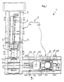
- the machine 1 has a horizontal rigid frame 2 comprising two horizontal modular structures perpendicular to each other 2A and 2B carrying the tire and the rasper respectively, secured together.
- the machine can also include a module making the casing with, for example, a third structure arranged opposite the grater.
- a module making the casing with, for example, a third structure arranged opposite the grater.
- the design of this retreading machine having great stability and great precision which that the size of the tires to be retreaded makes it possible to obtain a fully modular machine from the basic module supporting the pneumatic retread.
- the structure 2A comprises two rails 3 and 4 for guiding a carriage 5 having a vertical upright 6 on which is mounted a mandrel 7 for supporting a pneumatic, mounted on an axis of rotation 11 and having a rim 12 extendable, the mandrel 7 allowing the fitting of tires of dimensions very different, ranging from tourism to heavy goods vehicles (of course it can be useful to change the dimension of the rim 12).
- a motor 8, associated with a screw end 9 allows the carriage to be actuated to cause its translation along the rails 3 and 4, while a second motor 10 actuates the axis of rotation 11 of the mandrel 7 to allow the rotation of the latter.
- a motor allowing very precise positioning precise such as a numerically controlled motor.
- the guide rails 3 and 4 are arranged parallel to the axis of rotation 11 of the mandrel 7 and arranged symmetrically with respect to the vertical plane containing this axis.
- the spacing of the rails 3 and 4 is chosen taking into account the size of the machine and the stability of the structure. We can thus consider having a distance between the two rails which correspond substantially to the diameter of the rim 12.
- the length of the rails can be determined according to the number of modules capable of being arranged perpendicular to this structure.
- this structure 2A for supporting a tire with a translational movement parallel to the axis of the tire makes it possible not to during the translation of risk of deformation or vibration of the mandrel due to the heavy weight of a tire because we keep the barycenter from this last on the same axis.
- the arrangement of these two symmetrical rails allows to ensure a very great stability to this line of barycenter. Note also that the whole weight is directly supported by the structure that is to say by the very slab of the factory or the manufacturing workshop.
- the tire mounted on the mandrel is easily accessible without being placed in a frame or in a frame having vertical uprights which limit the possibilities of access for other tools to the pneumatic.
- the structure 2B also comprises two rails 20, 21 perpendicular to the rails 3 and 4 and which guide a second carriage 22 thus mounted in translation perpendicular to that of the mandrel 7 and also actuated by a motor digital control 23 which drives the carriage 22 using a second screw without late 24.
- grating tools 25 On the second carriage 22 are mounted the grating tools 25 with a motor 28 and a transmission to drive the grating tool, so that these are arranged in the median plane of the tire to be retreaded.
- These grating tools 25 are conventionally constituted by a series of circular blades mounted about an axis of rotation 26, this axis 26 being arranged vertically.
- the rails 20 and 21 are arranged apart and on the other side of the vertical plane containing the axis of rotation 26 and perpendicular to the axis of rotation 11 of the mandrel 7.
- the grater 25 is covered with a cover 27 to limit the scattering of dust generated during grating, a suction is then provided to evacuate this dust.
- the presence of these two spaced rails gives the grater a very good stability.
- the carriage 22 moving only on one axis there is very high stability, precision and a significant reduction in the level of noise.
Landscapes
- Engineering & Computer Science (AREA)
- Mechanical Engineering (AREA)
- Tyre Moulding (AREA)
- Moulds For Moulding Plastics Or The Like (AREA)
- Tires In General (AREA)
- Testing Of Balance (AREA)
- Graft Or Block Polymers (AREA)
- Heating, Cooling, Or Curing Plastics Or The Like In General (AREA)
Abstract
Description
De plus, la présence de ces montants latéraux rend difficile l'accès aux épaules du pneumatique. On fait alors souvent appel pour le déchapage à un robot porteur d'une râpe, mais là encore une augmentation de la taille du pneumatique entraíne une augmentation de la longueur et de la rigidité du bras du robot porteur de la râpe et par conséquent entraíne des problèmes de stabilité et de vibrations nuisant considérablement à la qualité et à la précision du travail réalisé par une telle machine.
Il faut également pour que la machine fonctionne pour un pneumatique très large, avoir prolongé les rails de guidage des outils de râpage suspendus au-dessus dudit pneumatique entraínant alors des vibrations plus importantes lors de la translation et de l'actionnement de ces outils de râpage.
- la figure 1 est une vue en élévation d'une machine conforme à l'invention,
- la figure 2 est une vue de côté de la machine représentée sur la figure 1 selon la flèche F.
Claims (9)
- Machine destinée au rechapage de pneumatiques ayant un bâti (2) comprenant au moins deux structures (2A, 2B) associées dont une première structure (2A) de support d'un pneumatique à rechaper qui comporte un mandrin de support (7) du pneumatique rotatif autour d'un axe de rotation (11), le mandrin (7) étant monté à translation sur ladite structure (2A), et dont une deuxième structure (2B) portant des outils de rechapage (25) du pneumatique montés à translation sur ladite deuxième structure dans une direction sensiblement perpendiculaire à celle de la translation du mandrin (7), caractérisé par le fait que la direction de la translation du mandrin (7) est parallèle à l'axe de rotation (11) dudit mandrin.
- Machine selon la revendication 1, dans laquelle le mandrin (7) est monté en translation sur deux rails de guidage (3, 4) parallèles à l'axe de rotation (11) dudit mandrin, les deux rails (3, 4) étant disposés symétriquement par rapport au plan contenant l'axe de rotation (11) du mandrin (7) et sensiblement perpendiculaire au plan contenant la surface des rails (3, 4).
- Machine selon l'une quelconque des revendications 1 ou 2, dans laquelle les outils de rechapage (25) ont montés à translation sur deux rails (20, 21) disposés symétriquement par rapport au plan contenant le centre des outils de rechapage (25) et sensiblement perpendiculaire au plan contenant la surface des rails (20, 21).
- Machine selon l'une quelconque des revendications 1 à 3, dans laquelle les mouvements de translation des outils de rechapage (25) et du mandrin (7) sont situés dans un même plan horizontal.
- Machine selon l'une quelconque des revendications 1 à 4, dans laquelle la deuxième structure (2B) comprend en plus des outils de rechapage (25), des organes de rouletage d'une nouvelle bande de roulement pour le pneumatique à rechaper après son application sur ce dernier.
- Machine selon l'une quelconque des revendications 1 à 5, dans laquelle les outils de rechapage sont constitués par des outils de râpage (25, 27) du pneumatique à rechaper.
- Machine selon la revendication 6, dans laquelle les outils de râpage (25, 27) comprennent une série de lames circulaires montées à rotation autour d'un axe de rotation (26), ledit axe de rotation étant disposé sensiblement perpendiculairement à la direction de translation desdits outils.
- Machine selon l'une quelconque des revendications 1 à 5, dans laquelle les outils de rechapage sont constitués par des outils d'application d'une bande de roulement.
- Machine selon l'une quelconque des revendications 1 à 8, comprenant une ou plusieurs autres structures portant respectivement des outils de rechapage du pneumatique à rechaper montés respectivement à translation sur la structure correspondante dans une direction sensiblement perpendiculaire à celle de la translation du mandrin.
Applications Claiming Priority (2)
| Application Number | Priority Date | Filing Date | Title |
|---|---|---|---|
| FR0009804 | 2000-07-21 | ||
| FR0009804 | 2000-07-21 |
Publications (3)
| Publication Number | Publication Date |
|---|---|
| EP1174254A2 true EP1174254A2 (fr) | 2002-01-23 |
| EP1174254A3 EP1174254A3 (fr) | 2003-07-23 |
| EP1174254B1 EP1174254B1 (fr) | 2005-10-26 |
Family
ID=8852940
Family Applications (1)
| Application Number | Title | Priority Date | Filing Date |
|---|---|---|---|
| EP01117198A Expired - Lifetime EP1174254B1 (fr) | 2000-07-21 | 2001-07-16 | Machine de rechapage de pneumatique |
Country Status (11)
| Country | Link |
|---|---|
| US (1) | US6911113B2 (fr) |
| EP (1) | EP1174254B1 (fr) |
| JP (1) | JP2002144448A (fr) |
| AT (1) | ATE307698T1 (fr) |
| AU (1) | AU782563B2 (fr) |
| BR (1) | BR0102947B1 (fr) |
| CA (1) | CA2353334C (fr) |
| DE (1) | DE60114312T2 (fr) |
| DK (1) | DK1174254T3 (fr) |
| ES (1) | ES2249364T3 (fr) |
| MX (1) | MXPA01007407A (fr) |
Families Citing this family (1)
| Publication number | Priority date | Publication date | Assignee | Title |
|---|---|---|---|---|
| EP2832495A4 (fr) * | 2012-03-26 | 2016-01-06 | Lucas Möller | Système de rechapage de pneus constitué d'un bras robotisé à mouvements d'interpolation angulaire |
Family Cites Families (16)
| Publication number | Priority date | Publication date | Assignee | Title |
|---|---|---|---|---|
| US2009524A (en) * | 1934-06-19 | 1935-07-30 | George A Schmidt | Used tire, facing, stitching, and retreading machine |
| US2528476A (en) * | 1942-03-20 | 1950-10-31 | Thomas Lipton Inc | Method and apparatus for dehydration |
| US2707851A (en) * | 1953-10-01 | 1955-05-10 | Goodrich Co B F | Tire sidewall finishing machine and method |
| US2945534A (en) * | 1959-02-13 | 1960-07-19 | Hawkinson Paul E Co | Tire buffing machine |
| US2965162A (en) * | 1959-08-26 | 1960-12-20 | Hawkinson Paul E Co | Tire buffing machine |
| US3528476A (en) * | 1968-03-08 | 1970-09-15 | Hawkinson Paul E Co | Tire buffing apparatus |
| AU1528470A (en) | 1969-05-19 | 1971-11-25 | Motorways Guz. ) Limited | Improvements in and relating to profile shaping apparatus |
| US3675706A (en) * | 1971-04-14 | 1972-07-11 | Cahill Mfg Co Inc | Tire buffing machine |
| IT1022033B (it) * | 1974-05-14 | 1978-03-20 | R T S Ring Tread System Intern | Macchina atta a consentire il trattamento di pneumatici usurati e la successiva applicazione sugli stessi di anelli battistrada prestampati |
| JPS5944221B2 (ja) * | 1975-03-20 | 1984-10-27 | オノダニキコウ カブシキガイシヤ | 更生タイヤ製造装置 |
| CA1157103A (fr) * | 1980-09-29 | 1983-11-15 | Bruce J. Renaud | Pneu vulcanise et methode de gravure |
| US4515200A (en) * | 1983-05-24 | 1985-05-07 | Williams Roy L | Apparatus for whitewalling vehicle tires |
| AU667674B2 (en) * | 1991-09-11 | 1996-04-04 | Bandag Licensing Corporation | Tire buffing apparatus |
| JPH05200911A (ja) * | 1992-01-28 | 1993-08-10 | Sumitomo Rubber Ind Ltd | 更生タイヤ用バフ装置 |
| JP2698032B2 (ja) * | 1993-10-21 | 1998-01-19 | 住友ゴム工業株式会社 | 台タイヤの自動投入・取り出し方法及びその装置 |
| EP0955154B1 (fr) * | 1998-05-05 | 2003-03-26 | Recamic S.A. | Machine de rechapage de pneumatiques |
-
2001
- 2001-07-16 EP EP01117198A patent/EP1174254B1/fr not_active Expired - Lifetime
- 2001-07-16 DK DK01117198T patent/DK1174254T3/da active
- 2001-07-16 ES ES01117198T patent/ES2249364T3/es not_active Expired - Lifetime
- 2001-07-16 AT AT01117198T patent/ATE307698T1/de not_active IP Right Cessation
- 2001-07-16 DE DE60114312T patent/DE60114312T2/de not_active Expired - Lifetime
- 2001-07-18 BR BRPI0102947-9A patent/BR0102947B1/pt not_active IP Right Cessation
- 2001-07-19 CA CA2353334A patent/CA2353334C/fr not_active Expired - Fee Related
- 2001-07-19 US US09/909,272 patent/US6911113B2/en not_active Expired - Lifetime
- 2001-07-20 MX MXPA01007407A patent/MXPA01007407A/es active IP Right Grant
- 2001-07-20 AU AU55892/01A patent/AU782563B2/en not_active Ceased
- 2001-07-23 JP JP2001255314A patent/JP2002144448A/ja active Pending
Also Published As
| Publication number | Publication date |
|---|---|
| AU782563B2 (en) | 2005-08-11 |
| EP1174254A3 (fr) | 2003-07-23 |
| US6911113B2 (en) | 2005-06-28 |
| DE60114312D1 (de) | 2005-12-01 |
| MXPA01007407A (es) | 2003-05-19 |
| JP2002144448A (ja) | 2002-05-21 |
| ES2249364T3 (es) | 2006-04-01 |
| CA2353334C (fr) | 2010-09-14 |
| BR0102947B1 (pt) | 2009-08-11 |
| AU5589201A (en) | 2002-01-24 |
| US20020017356A1 (en) | 2002-02-14 |
| DK1174254T3 (da) | 2006-03-20 |
| BR0102947A (pt) | 2002-03-05 |
| DE60114312T2 (de) | 2006-07-06 |
| ATE307698T1 (de) | 2005-11-15 |
| CA2353334A1 (fr) | 2002-01-21 |
| EP1174254B1 (fr) | 2005-10-26 |
Similar Documents
| Publication | Publication Date | Title |
|---|---|---|
| EP0955154B1 (fr) | Machine de rechapage de pneumatiques | |
| EP3363553B1 (fr) | Machine de roulage de tôles, ainsi que procédé de roulage d'une tôle utilisant une telle machine de roulage | |
| WO2004087374A1 (fr) | Machine de meulage de verres optiques | |
| FR2922127A1 (fr) | Machine a cintrer un profile et outillage de cintrage pour une telle machine | |
| FR2743741A1 (fr) | Structure logique d'une machine-outil d'usinage a grande vitesse du type porte-broche | |
| BE543618A (fr) | ||
| EP3685935A1 (fr) | Sertisseuse de boites de forme a came electronique | |
| WO1985001898A1 (fr) | Machine automatique perfectionnee pour cambrer selon une configuration spatiale des elements minces et rectilignes, et notamment des fils metalliques | |
| EP1174254B1 (fr) | Machine de rechapage de pneumatique | |
| EP1392531B1 (fr) | Machine de presentation a axe horizontal de pneumatique | |
| EP0114774B1 (fr) | Chargeur-extracteur de pièces à un seul moteur de commande | |
| WO2002089300A1 (fr) | Dispositif pour le formage des developpantes d'enroulements de machines tournantes electriques | |
| WO2000046096A1 (fr) | Procede de mise en conformation geometrique pour la caisse de vehicules automobiles | |
| WO2003103994A1 (fr) | Procede et unite de montage sur une jante d'un pneu pourvu d'un appui de securite | |
| EP3458253B1 (fr) | Procédé et installation de retroussage d'une ébauche de pneumatique | |
| EP3819050A1 (fr) | Tour en fosse modulaire et portatif | |
| FR2774613A1 (fr) | Dispositif motorise pour la coupe de tubes | |
| EP3156777A1 (fr) | Dispositif de montage/demontage de pneumatique d'une roue de vehicule et d'equilibrage de roue | |
| FR2711335A1 (fr) | Dispositif de manutention de roue de véhicule. | |
| WO2004108490A1 (fr) | Machine de depoussierage pour ateliers de peinture de carrosseries de vehicules automobiles | |
| FR2831842A1 (fr) | Machine automatique pour le formage de barres | |
| FR2685228A1 (fr) | Machine a cintrer un element du type tige, barre, tube, fil ou analogue. | |
| FR2884163A1 (fr) | Machine de meulage de verres optiques munie d'une meule de finition inclinee et verre optique correspondant | |
| FR3028492A1 (fr) | Installation destinee a assurer le deplacement d'une charge | |
| FR2791917A1 (fr) | Procede de realisation d'une machine a rectifier de precision du type comprenant un bati et machine a rectifier de precision correspondante |
Legal Events
| Date | Code | Title | Description |
|---|---|---|---|
| PUAI | Public reference made under article 153(3) epc to a published international application that has entered the european phase |
Free format text: ORIGINAL CODE: 0009012 |
|
| AK | Designated contracting states |
Kind code of ref document: A2 Designated state(s): AT BE CH CY DE DK ES FI FR GB GR IE IT LI LU MC NL PT SE TR |
|
| AX | Request for extension of the european patent |
Free format text: AL;LT;LV;MK;RO;SI |
|
| PUAL | Search report despatched |
Free format text: ORIGINAL CODE: 0009013 |
|
| AK | Designated contracting states |
Designated state(s): AT BE CH CY DE DK ES FI FR GB GR IE IT LI LU MC NL PT SE TR |
|
| AX | Request for extension of the european patent |
Extension state: AL LT LV MK RO SI |
|
| RIC1 | Information provided on ipc code assigned before grant |
Ipc: 7B 24B 5/36 A |
|
| 17P | Request for examination filed |
Effective date: 20040123 |
|
| AKX | Designation fees paid |
Designated state(s): AT BE CH CY DE DK ES FI FR GB GR IE IT LI LU MC NL PT SE TR |
|
| 17Q | First examination report despatched |
Effective date: 20040727 |
|
| GRAP | Despatch of communication of intention to grant a patent |
Free format text: ORIGINAL CODE: EPIDOSNIGR1 |
|
| GRAS | Grant fee paid |
Free format text: ORIGINAL CODE: EPIDOSNIGR3 |
|
| GRAA | (expected) grant |
Free format text: ORIGINAL CODE: 0009210 |
|
| AK | Designated contracting states |
Kind code of ref document: B1 Designated state(s): AT BE CH CY DE DK ES FI FR GB GR IE IT LI LU MC NL PT SE TR |
|
| PG25 | Lapsed in a contracting state [announced via postgrant information from national office to epo] |
Ref country code: NL Free format text: LAPSE BECAUSE OF FAILURE TO SUBMIT A TRANSLATION OF THE DESCRIPTION OR TO PAY THE FEE WITHIN THE PRESCRIBED TIME-LIMIT Effective date: 20051026 Ref country code: IE Free format text: LAPSE BECAUSE OF FAILURE TO SUBMIT A TRANSLATION OF THE DESCRIPTION OR TO PAY THE FEE WITHIN THE PRESCRIBED TIME-LIMIT Effective date: 20051026 Ref country code: AT Free format text: LAPSE BECAUSE OF FAILURE TO SUBMIT A TRANSLATION OF THE DESCRIPTION OR TO PAY THE FEE WITHIN THE PRESCRIBED TIME-LIMIT Effective date: 20051026 Ref country code: FI Free format text: LAPSE BECAUSE OF FAILURE TO SUBMIT A TRANSLATION OF THE DESCRIPTION OR TO PAY THE FEE WITHIN THE PRESCRIBED TIME-LIMIT Effective date: 20051026 |
|
| REG | Reference to a national code |
Ref country code: GB Ref legal event code: FG4D Free format text: NOT ENGLISH |
|
| REG | Reference to a national code |
Ref country code: CH Ref legal event code: EP |
|
| REG | Reference to a national code |
Ref country code: IE Ref legal event code: FG4D Free format text: LANGUAGE OF EP DOCUMENT: FRENCH |
|
| REF | Corresponds to: |
Ref document number: 60114312 Country of ref document: DE Date of ref document: 20051201 Kind code of ref document: P |
|
| REG | Reference to a national code |
Ref country code: SE Ref legal event code: TRGR |
|
| PG25 | Lapsed in a contracting state [announced via postgrant information from national office to epo] |
Ref country code: GR Free format text: LAPSE BECAUSE OF FAILURE TO SUBMIT A TRANSLATION OF THE DESCRIPTION OR TO PAY THE FEE WITHIN THE PRESCRIBED TIME-LIMIT Effective date: 20060126 |
|
| GBT | Gb: translation of ep patent filed (gb section 77(6)(a)/1977) |
Effective date: 20060109 |
|
| REG | Reference to a national code |
Ref country code: DK Ref legal event code: T3 |
|
| PG25 | Lapsed in a contracting state [announced via postgrant information from national office to epo] |
Ref country code: PT Free format text: LAPSE BECAUSE OF FAILURE TO SUBMIT A TRANSLATION OF THE DESCRIPTION OR TO PAY THE FEE WITHIN THE PRESCRIBED TIME-LIMIT Effective date: 20060327 |
|
| REG | Reference to a national code |
Ref country code: ES Ref legal event code: FG2A Ref document number: 2249364 Country of ref document: ES Kind code of ref document: T3 |
|
| NLV1 | Nl: lapsed or annulled due to failure to fulfill the requirements of art. 29p and 29m of the patents act | ||
| REG | Reference to a national code |
Ref country code: IE Ref legal event code: FD4D |
|
| PG25 | Lapsed in a contracting state [announced via postgrant information from national office to epo] |
Ref country code: MC Free format text: LAPSE BECAUSE OF NON-PAYMENT OF DUE FEES Effective date: 20060731 Ref country code: LI Free format text: LAPSE BECAUSE OF NON-PAYMENT OF DUE FEES Effective date: 20060731 Ref country code: CH Free format text: LAPSE BECAUSE OF NON-PAYMENT OF DUE FEES Effective date: 20060731 Ref country code: BE Free format text: LAPSE BECAUSE OF NON-PAYMENT OF DUE FEES Effective date: 20060731 |
|
| PLBE | No opposition filed within time limit |
Free format text: ORIGINAL CODE: 0009261 |
|
| STAA | Information on the status of an ep patent application or granted ep patent |
Free format text: STATUS: NO OPPOSITION FILED WITHIN TIME LIMIT |
|
| 26N | No opposition filed |
Effective date: 20060727 |
|
| REG | Reference to a national code |
Ref country code: CH Ref legal event code: PL |
|
| BERE | Be: lapsed |
Owner name: RECAMIC S.A. Effective date: 20060731 |
|
| PG25 | Lapsed in a contracting state [announced via postgrant information from national office to epo] |
Ref country code: TR Free format text: LAPSE BECAUSE OF FAILURE TO SUBMIT A TRANSLATION OF THE DESCRIPTION OR TO PAY THE FEE WITHIN THE PRESCRIBED TIME-LIMIT Effective date: 20051026 Ref country code: LU Free format text: LAPSE BECAUSE OF NON-PAYMENT OF DUE FEES Effective date: 20060716 |
|
| PG25 | Lapsed in a contracting state [announced via postgrant information from national office to epo] |
Ref country code: CY Free format text: LAPSE BECAUSE OF FAILURE TO SUBMIT A TRANSLATION OF THE DESCRIPTION OR TO PAY THE FEE WITHIN THE PRESCRIBED TIME-LIMIT Effective date: 20051026 |
|
| PGFP | Annual fee paid to national office [announced via postgrant information from national office to epo] |
Ref country code: ES Payment date: 20150728 Year of fee payment: 15 Ref country code: DK Payment date: 20150721 Year of fee payment: 15 Ref country code: GB Payment date: 20150721 Year of fee payment: 15 |
|
| REG | Reference to a national code |
Ref country code: FR Ref legal event code: PLFP Year of fee payment: 16 |
|
| REG | Reference to a national code |
Ref country code: DK Ref legal event code: EBP Effective date: 20170131 |
|
| GBPC | Gb: european patent ceased through non-payment of renewal fee |
Effective date: 20160716 |
|
| PG25 | Lapsed in a contracting state [announced via postgrant information from national office to epo] |
Ref country code: GB Free format text: LAPSE BECAUSE OF NON-PAYMENT OF DUE FEES Effective date: 20160716 |
|
| REG | Reference to a national code |
Ref country code: FR Ref legal event code: PLFP Year of fee payment: 17 |
|
| PG25 | Lapsed in a contracting state [announced via postgrant information from national office to epo] |
Ref country code: DK Free format text: LAPSE BECAUSE OF NON-PAYMENT OF DUE FEES Effective date: 20160731 |
|
| PG25 | Lapsed in a contracting state [announced via postgrant information from national office to epo] |
Ref country code: ES Free format text: LAPSE BECAUSE OF NON-PAYMENT OF DUE FEES Effective date: 20160717 |
|
| REG | Reference to a national code |
Ref country code: FR Ref legal event code: PLFP Year of fee payment: 18 |
|
| PGFP | Annual fee paid to national office [announced via postgrant information from national office to epo] |
Ref country code: IT Payment date: 20180724 Year of fee payment: 18 Ref country code: FR Payment date: 20180725 Year of fee payment: 18 Ref country code: DE Payment date: 20180723 Year of fee payment: 18 |
|
| REG | Reference to a national code |
Ref country code: ES Ref legal event code: FD2A Effective date: 20181128 |
|
| PGFP | Annual fee paid to national office [announced via postgrant information from national office to epo] |
Ref country code: SE Payment date: 20180719 Year of fee payment: 18 |
|
| REG | Reference to a national code |
Ref country code: DE Ref legal event code: R119 Ref document number: 60114312 Country of ref document: DE |
|
| REG | Reference to a national code |
Ref country code: SE Ref legal event code: EUG |
|
| PG25 | Lapsed in a contracting state [announced via postgrant information from national office to epo] |
Ref country code: DE Free format text: LAPSE BECAUSE OF NON-PAYMENT OF DUE FEES Effective date: 20200201 Ref country code: SE Free format text: LAPSE BECAUSE OF NON-PAYMENT OF DUE FEES Effective date: 20190717 |
|
| PG25 | Lapsed in a contracting state [announced via postgrant information from national office to epo] |
Ref country code: FR Free format text: LAPSE BECAUSE OF NON-PAYMENT OF DUE FEES Effective date: 20190731 |
|
| PG25 | Lapsed in a contracting state [announced via postgrant information from national office to epo] |
Ref country code: IT Free format text: LAPSE BECAUSE OF NON-PAYMENT OF DUE FEES Effective date: 20190716 |