EP1174579A2 - Dispositif d'étanchéité pour une porte sans seuil - Google Patents
Dispositif d'étanchéité pour une porte sans seuil Download PDFInfo
- Publication number
- EP1174579A2 EP1174579A2 EP01103830A EP01103830A EP1174579A2 EP 1174579 A2 EP1174579 A2 EP 1174579A2 EP 01103830 A EP01103830 A EP 01103830A EP 01103830 A EP01103830 A EP 01103830A EP 1174579 A2 EP1174579 A2 EP 1174579A2
- Authority
- EP
- European Patent Office
- Prior art keywords
- guide rail
- profile
- sealing
- leg
- sealing body
- Prior art date
- Legal status (The legal status is an assumption and is not a legal conclusion. Google has not performed a legal analysis and makes no representation as to the accuracy of the status listed.)
- Granted
Links
- 238000007789 sealing Methods 0.000 title claims abstract description 114
- 239000000463 material Substances 0.000 claims description 11
- 230000002349 favourable effect Effects 0.000 claims description 5
- 238000006073 displacement reaction Methods 0.000 claims description 4
- 239000004810 polytetrafluoroethylene Substances 0.000 claims description 4
- 229920001343 polytetrafluoroethylene Polymers 0.000 claims description 4
- 239000010410 layer Substances 0.000 description 8
- 238000004873 anchoring Methods 0.000 description 5
- 238000005299 abrasion Methods 0.000 description 3
- 238000009413 insulation Methods 0.000 description 3
- 230000007246 mechanism Effects 0.000 description 3
- 229910052782 aluminium Inorganic materials 0.000 description 2
- XAGFODPZIPBFFR-UHFFFAOYSA-N aluminium Chemical compound [Al] XAGFODPZIPBFFR-UHFFFAOYSA-N 0.000 description 2
- 239000013013 elastic material Substances 0.000 description 2
- 238000000034 method Methods 0.000 description 2
- 230000008569 process Effects 0.000 description 2
- 230000008719 thickening Effects 0.000 description 2
- 210000002105 tongue Anatomy 0.000 description 2
- 238000005452 bending Methods 0.000 description 1
- 230000008901 benefit Effects 0.000 description 1
- 230000008859 change Effects 0.000 description 1
- 230000000694 effects Effects 0.000 description 1
- 239000011888 foil Substances 0.000 description 1
- 238000009434 installation Methods 0.000 description 1
- 238000004519 manufacturing process Methods 0.000 description 1
- 230000013011 mating Effects 0.000 description 1
- 229910052751 metal Inorganic materials 0.000 description 1
- 239000002184 metal Substances 0.000 description 1
- 239000004033 plastic Substances 0.000 description 1
- 230000009467 reduction Effects 0.000 description 1
- 239000002344 surface layer Substances 0.000 description 1
- 229920001169 thermoplastic Polymers 0.000 description 1
- 239000004416 thermosoftening plastic Substances 0.000 description 1
Images

Classifications
-
- E—FIXED CONSTRUCTIONS
- E06—DOORS, WINDOWS, SHUTTERS, OR ROLLER BLINDS IN GENERAL; LADDERS
- E06B—FIXED OR MOVABLE CLOSURES FOR OPENINGS IN BUILDINGS, VEHICLES, FENCES OR LIKE ENCLOSURES IN GENERAL, e.g. DOORS, WINDOWS, BLINDS, GATES
- E06B7/00—Special arrangements or measures in connection with doors or windows
- E06B7/16—Sealing arrangements on wings or parts co-operating with the wings
- E06B7/18—Sealing arrangements on wings or parts co-operating with the wings by means of movable edgings, e.g. draught sealings additionally used for bolting, e.g. by spring force or with operating lever
- E06B7/20—Sealing arrangements on wings or parts co-operating with the wings by means of movable edgings, e.g. draught sealings additionally used for bolting, e.g. by spring force or with operating lever automatically withdrawn when the wing is opened, e.g. by means of magnetic attraction, a pin or an inclined surface, especially for sills
- E06B7/215—Sealing arrangements on wings or parts co-operating with the wings by means of movable edgings, e.g. draught sealings additionally used for bolting, e.g. by spring force or with operating lever automatically withdrawn when the wing is opened, e.g. by means of magnetic attraction, a pin or an inclined surface, especially for sills with sealing strip being moved to a retracted position by elastic means, e.g. springs
Definitions
- the invention relates to a sealing arrangement for a threshold-free door, with a a receiving groove in the lower edge of a door wing insertable guide rail and with a on a retaining profile in this attached sealing body, which is between one in the Guide rail retracted, upper and one protruding from this, extended, lower position is displaceable and one in the latter against a floor or a door frame Pressable, lying below the holding profile sealing section, which is on both sides of the Holding profile each with this laterally comprehensive, protruding into the interior of the guide rails
- Side legs is provided, each of which is on the associated side wall of the Slidably supports the guide rail and also next to one also inside the Guide rail extending lateral profile leg of the holding profile lies.
- a U-shaped plastic profile bar attached, which is also used for floor to be sealed open and with its central web on top of the central web of the holding profile is attached so that its side legs between the side legs of the holding profile and the Side walls of the guide rail extend and are so spread outwards that they are in Area of their free ends on the facing inside of the guide rail slide.
- This known sealing arrangement is relatively expensive to assemble and is also with regard to Noise reduction not very effective.
- a sealing arrangement of the type mentioned at the outset is described in EP 0 338 974 B1.
- the holding profile has a U-shaped inside the U-shaped guide rail Section, but the opening against the orientation of the U
- the guide rail is open into the interior of the guide rail.
- the well-known Sealing arrangement consists essentially of one to be sealed in the direction Elastic sealing strip protruding towards the opposite surface, each on one of its two sides side legs extending into the interior of the guide rail.
- the sealing strip Projections are held in a form-fitting manner in correspondingly provided holding recesses, wherein the side legs from this attachment point at an angle towards the assigned Side wall of the guide rail run out and sliding with its free end on this issue.
- the structure of this known seal arrangement is simpler than in the next Prior art cited above.
- the side legs of the sealing body have a relatively large contact area at its free end against the side wall of the guide rail apply, there are comparatively large frictional forces with a relative displacement, what in the course of time to a noticeable abrasion and thus to a decrease in Sealing effect against the outside of the sealing arrangement leads and at the expense of it Lifetime goes.
- this known sealing arrangement is also in terms of its Noise insulation properties (in the sealing state) are not particularly favorable.
- the invention has for its object a sealing arrangement type mentioned at the outset so that in the sealing position (extended state of the sealing body) the sound insulation is improved.
- each side leg of the elastic sealing body with its free end region against the end face of the free end of the profile leg of the holding profile arranged next to it is present under pressure, this end surface at least partially covered laterally and on its side facing the corresponding side wall of the guide rail several in Direction of displacement of the sealing body offset parallel to each other, essentially over its entire length extending elastic projections are provided to the sliding system serve the side wall of the guide rail, being in the extended position of the Sealing body still at least two of these projections of each side leg in contact stand with the side wall of the guide rail.
- the multiple arrangement of the lateral Sliding projections achieved that even at least in the extended state of the seal two, but preferably even more of these projections are still in contact with the system facing side surface of the guide rail. Because the projections in the direction of displacement are arranged offset to each other and each over the entire length of the relevant Side legs of the seal body will run between them, also in this one extended state of the sealing body, over the entire length of the guide rail away from each other by the projections, each self-contained spaces created, which creates effective sound insulation from the outside of the door through the Interior of the guide rail is reached through.
- the shape as well as the number of protrusions on the side legs of the elastic Seal body can be set in a suitable manner, including for a specific Design case special configurations can be made. However, it has proven to be proven particularly advantageous if the projections in cross section in the form of curved knobs, in particular are semicircularly curved.
- each side leg of the elastic sealing body attached Four projections are preferred on each side leg of the elastic sealing body attached, which leads to a fully satisfactory function in most applications. If however, longer distances are required to reach the extended position of the sealing body should be, it is also easily possible to have a larger number of protrusions on both Attach side legs of the elastic sealing body.
- each side leg on its the inner wall of the guide rail facing side is provided with a support layer on which the projections (in one piece) are formed and which consists of a material with particularly favorable friction properties, with, particularly preferably, this material of the support layer and the projections being a larger one Has hardness than that of the elastic sealing body. So it is possible that by appropriate Choice of the material for the overlay and the protrusions specifically those that occur Friction can be taken into account, while regardless of the material of the Sealing body whose sealing function can be optimally adapted in the extended state can.
- each profile leg of the holding profile assigned side leg of the sealing body facing side of the position of the projections correspondingly arranged depressions are formed.
- the sealing section of the Sealing body formed in the form of a hollow cross section, which on its the holding profile facing side abuts against this and there is a centrally located, towards the Retaining profile projecting support foot (which is made of the same elastic material as the Sealing body) has, which in an assigned central receiving opening of the Holding profile engages and is positively supported there.
- the sealing section is preferably on its side facing away from the holding profile in the form of an formed essentially circular arc-shaped sealing web which at Press against the counter surface to be sealed (floor or door frame) against it Bulging can easily compress.
- each Side legs of the sealing body designed so that it over the end face of the free end of the profile leg of the holding profile extending next to it also protrudes. It will possible that with a suitable dimensioning of the guide rail and the other elements the sealing arrangement according to the invention with the fully retracted state, the free end of each Side legs between the end face of each profile leg and the central portion of the Guide rail can be slightly squeezed, which in the retracted state of the Sealing body due to the crushing that otherwise occurs in such Seal arrangements existing rattling noises in the interior of the Guide rail can be avoided completely.
- the guide rail can be designed in any suitable shape, but has a very special feature preferably has a U-shaped cross-section which is directed towards the floor to be sealed, Frame or the like is open.
- the holding profile also preferably forms on its upper part which surrounds the profile leg Section of a U-shaped cross section, which, opposite to the opening direction of the U cross section the guide rail is open into the interior of the guide rail.
- a particularly preferred embodiment of the sealing body according to the invention also exists in that the end face of each profile leg of the holding profile of which the side wall of the assigned guide rail facing the outside obliquely in the direction of the other profile leg, that is, into the interior of the space spanned by the guide rail there, runs.
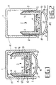
- FIG. 1 a sealing arrangement for a threshold-free door is shown (in cross section), 1 shows the retracted state and FIG. 2 the extended sealing state.
- the sealing arrangement consists of a cross-sectionally U-shaped guide rail 1 in shape of an aluminum extruded profile, but it is also readily as a corresponding bent sheet metal part or can be made in any other suitable form.
- a support profile 2 also in the form of an aluminum extruded profile, arranged, which in its upper, d. H. the opening of the U-profile Section facing away from the guide rail 1, however, into the interior of the guide rail 1 has open U-shaped training.
- This consists of two side profile legs 3 and 4, which their feet are connected to each other via a transverse connecting web 5.
- the lateral profile legs 3, 4 run in their Extension still beyond the junction of the connecting web 5 and form below the same (i.e. on its side facing away from the interior of the guide rail 1), that is to say in 1 and 2 lower side, a profile section, which for receiving and anchoring Holding foot 6 is used, which in turn on a sealing body 7 made of elastic, for.
- the holding foot 6 can be made in one piece with the Seal body, so be made with the same material as this. In which Embodiment in the figures, however, it consists of a different material than that Sealing body 7, which is used for good anchoring within the holding section of the support profile 2 is particularly suitable.
- the sealing body 7 has on both sides in cross section side legs 8 and 9, the one of Hollow profile formed sealing section 10 in the formed by the guide rail 1 Protrude inside.
- Each side leg 8, 9 is on its associated side wall 11 of the guide rail 1 facing side with a support layer 12, which is made of a harder elastic Material as the sealing body 7 and with the side wall 11 of the guide rail 1 out bulging projections or knobs 13 is provided.
- a support layer 12 which is made of a harder elastic Material as the sealing body 7 and with the side wall 11 of the guide rail 1 out bulging projections or knobs 13 is provided.
- Sealing arrangements are attached to each side leg 8 or 9 four projections 13, which over the entire longitudinal extent of the side legs 8 and 9 (perpendicular to Drawing plane of Figures 1 and 2) run and are arranged parallel to each other, wherein they in Direction of movement of the sealing body 7 in and out relative to the profile rail 1 are attached offset to each other.
- the distances between two neighboring ones Projections 13 on each leg 8 or 9 can each be the same size or different be selected, but the distances and the number of projections 13 are provided such that in the extended position of sealing body 7 and holding profile 3 shown in cross section in FIG. 2 at least two (in the embodiment shown: even three) projections 13 on each Side legs 8, 9 still remain in contact with the side wall 11 of the guide rail 1 (see illustration of FIG. 2).
- the design of the cross-sectional shape of the sliding knobs 13 is preferably chosen to be semicircular, as is the case with the exemplary embodiment shown. However, it could be another Cross-sectional shape for the projections 13 are used, in particular in cross-section recommend rounded protrusions.
- the lateral profile legs 3 and 4 of the holding profile 2 are inclined at their free ends extending end surfaces 14 and 15 provided obliquely in the illustration of FIGS. 1 and 2 at the top (in the direction of the opposite profile leg 4 or 3, ie rise from the assigned side wall 11 of the guide rail 1).
- the side legs 8 and 9 of the elastic sealing body 7 are with their end regions 15 and 16 in the direction of the associated inclined end face 14 or 15 of the adjacent profile leg 3 or 4 angled towards each and rest against this under elastic compressive prestress. there These end regions 15, 16 completely cover the relevant end surface 14, 15, as shown in FIG. 1 and 2 is shown.
- the support layer 12 also extends on each Side legs 8, 9 up to its free end, so that they also the angled end portion 14th or 15 covered on the outside.
- this sealing web 20 are two on its two side areas in the direction of the on the corresponding side projecting short sealing tongues 21, 22 attached.
- the sealing web 20 with the two sealing tongues 21 and 22 lies on the counter surface 23 to be sealed, for example on a floor or around the door in question frames running around, sealing under pressure.
- the holding foot 6 is attached to this, which in a corresponding central opening protrudes on the facing side of the holding profile 2 and with two anchoring sections 24 projecting laterally at its projecting end, 25, which are only shown schematically in FIGS. 1 and 2, a suitable form-fitting Anchoring, possibly with elastic bending of the holding sections 24 and 25, in the Recording space of the holding profile 2 ensures.
- FIG. 1 and 4 show cross sections through two further embodiments of such Sealing arrangement, in each case in a position corresponding to the illustration in FIG. 1.
- the configuration of the arrangement from FIG. 3 differs from that according to FIGS. 1 and 2 in essentially in that there the free end regions 15, 16 clearly above the assigned End faces 14 and 14 ', that is, the profile legs 3, 4 protrude upwards.
- the end position of the retracted Location of the overall arrangement a little more in the direction of the upper end surface 26 of the Guide rail 1 out, as shown in Fig. 3, is so that the free ends of the End sections 15, 16 against the upper inner surface 26 of the guide rail 1 under lighter Compressive bias come to the system.
- This can result in such a fully retracted Seal arrangement can be ensured that there is no rattling noises at a Swiveling of the door wing (not shown) comes.
- This is a very important point of view since such sealing arrangements for thresholdless doors in connection with the (not in all figures Actuating mechanism for the holding profile 2 tend to rattle.
- each recess 27 runs, like the associated projections 13, each over the entire Length of the relevant side leg 8 or 9 away.
- knob-shaped projections 13 z. B. made of PTFE are trained, optimally low frictional forces when retracting and extending the Sealing arrangement and at the same time achieve a particularly low abrasion during the rubbing process. Therefore one can z. B. the support layer 12 with the knobs 13 made of PTFE overall or, if another material is to be used, you can use a thin one Manufacture the top surface layer from PTFE (e.g. in the form of applied foils or similar) so that the advantage mentioned can be achieved in any case.
Landscapes
- Engineering & Computer Science (AREA)
- Civil Engineering (AREA)
- Structural Engineering (AREA)
- Specific Sealing Or Ventilating Devices For Doors And Windows (AREA)
- Support Devices For Sliding Doors (AREA)
- Sealing Material Composition (AREA)
Applications Claiming Priority (2)
| Application Number | Priority Date | Filing Date | Title |
|---|---|---|---|
| DE10035378 | 2000-07-20 | ||
| DE10035378A DE10035378B4 (de) | 2000-07-20 | 2000-07-20 | Dichtungsanordnung für eine schwellenlose Türe |
Publications (3)
| Publication Number | Publication Date |
|---|---|
| EP1174579A2 true EP1174579A2 (fr) | 2002-01-23 |
| EP1174579A3 EP1174579A3 (fr) | 2003-07-16 |
| EP1174579B1 EP1174579B1 (fr) | 2004-05-19 |
Family
ID=7649628
Family Applications (1)
| Application Number | Title | Priority Date | Filing Date |
|---|---|---|---|
| EP01103830A Expired - Lifetime EP1174579B1 (fr) | 2000-07-20 | 2001-02-15 | Dispositif d'étanchéité pour une porte sans seuil |
Country Status (3)
| Country | Link |
|---|---|
| EP (1) | EP1174579B1 (fr) |
| AT (1) | ATE267333T1 (fr) |
| DE (2) | DE10035378B4 (fr) |
Cited By (3)
| Publication number | Priority date | Publication date | Assignee | Title |
|---|---|---|---|---|
| WO2004053274A1 (fr) * | 2002-12-12 | 2004-06-24 | C.C.E. Srl | Bourrelet, notamment pour portes et analogue |
| DE102014116747A1 (de) | 2014-11-17 | 2016-05-19 | Athmer Ohg | Türspaltdichtung |
| CN108758185A (zh) * | 2018-08-03 | 2018-11-06 | 合肥联宝信息技术有限公司 | 一种减震脚垫及电子设备 |
Families Citing this family (1)
| Publication number | Priority date | Publication date | Assignee | Title |
|---|---|---|---|---|
| DE20208182U1 (de) * | 2002-05-25 | 2003-10-16 | Fa. F. Athmer, 59757 Arnsberg | Dichtungsprofil für eine Türdichtungsvorrichtung sowie Türdichtungsvorrichtung |
Citations (2)
| Publication number | Priority date | Publication date | Assignee | Title |
|---|---|---|---|---|
| DE3237524A1 (de) | 1982-10-09 | 1984-04-12 | Fa. F. Athmer, 5760 Arnsberg | Fussbodenseitige tuerdichtungsvorrichtung |
| EP0338974A2 (fr) | 1988-04-19 | 1989-10-25 | " Planet" Matthias Jaggi | Dispositif d'étanchéité pour portes sans seuil |
Family Cites Families (6)
| Publication number | Priority date | Publication date | Assignee | Title |
|---|---|---|---|---|
| DE1095500B (de) * | 1959-02-17 | 1960-12-22 | Athmer Fa F | Tuerabdichtung |
| US3453780A (en) * | 1968-02-05 | 1969-07-08 | Thompson Canfield Inc | Weather sealing insert for doors |
| DE3124106A1 (de) * | 1981-06-19 | 1982-12-30 | Fa. F. Athmer, 5760 Arnsberg | "abdichtungsvorrichtung fuer tueren" |
| DE29717673U1 (de) * | 1997-10-02 | 1997-11-20 | Fa. F. Athmer, 59757 Arnsberg | Gummiprofildichtung für eine Türdichtungsvorrichtung |
| DE29720659U1 (de) * | 1997-11-21 | 1998-01-08 | Fa. F. Athmer, 59757 Arnsberg | Vorrichtung zum Abdichten des unteren Spaltes einer Tür |
| DE20002108U1 (de) * | 2000-02-07 | 2000-04-20 | PLANET GDZ AG, Nürensdorf | Türflügel für eine schwellenlose Türe |
-
2000
- 2000-07-20 DE DE10035378A patent/DE10035378B4/de not_active Expired - Fee Related
-
2001
- 2001-02-15 DE DE50102312T patent/DE50102312D1/de not_active Expired - Fee Related
- 2001-02-15 AT AT01103830T patent/ATE267333T1/de not_active IP Right Cessation
- 2001-02-15 EP EP01103830A patent/EP1174579B1/fr not_active Expired - Lifetime
Patent Citations (2)
| Publication number | Priority date | Publication date | Assignee | Title |
|---|---|---|---|---|
| DE3237524A1 (de) | 1982-10-09 | 1984-04-12 | Fa. F. Athmer, 5760 Arnsberg | Fussbodenseitige tuerdichtungsvorrichtung |
| EP0338974A2 (fr) | 1988-04-19 | 1989-10-25 | " Planet" Matthias Jaggi | Dispositif d'étanchéité pour portes sans seuil |
Cited By (5)
| Publication number | Priority date | Publication date | Assignee | Title |
|---|---|---|---|---|
| WO2004053274A1 (fr) * | 2002-12-12 | 2004-06-24 | C.C.E. Srl | Bourrelet, notamment pour portes et analogue |
| DE102014116747A1 (de) | 2014-11-17 | 2016-05-19 | Athmer Ohg | Türspaltdichtung |
| DE102014116747B4 (de) | 2014-11-17 | 2023-10-05 | Athmer Ohg | Türspaltdichtung |
| CN108758185A (zh) * | 2018-08-03 | 2018-11-06 | 合肥联宝信息技术有限公司 | 一种减震脚垫及电子设备 |
| CN108758185B (zh) * | 2018-08-03 | 2024-02-23 | 合肥联宝信息技术有限公司 | 一种减震脚垫及电子设备 |
Also Published As
| Publication number | Publication date |
|---|---|
| DE50102312D1 (de) | 2004-06-24 |
| DE10035378B4 (de) | 2004-07-22 |
| ATE267333T1 (de) | 2004-06-15 |
| DE10035378A1 (de) | 2002-02-07 |
| EP1174579A3 (fr) | 2003-07-16 |
| EP1174579B1 (fr) | 2004-05-19 |
Similar Documents
| Publication | Publication Date | Title |
|---|---|---|
| AT402838B (de) | Dichtungsvorrichtung, insbesondere für türflügel | |
| EP3165703B1 (fr) | Dispositif d'étanchéité abaissable | |
| EP2088275B1 (fr) | Profilé d'étanchéité de côtés, notamment pour profilés de cadre et installations de portes coulissantes en étant équipées | |
| WO2012025593A1 (fr) | Colonne pour meuble réglable en hauteur | |
| EP2754805B1 (fr) | Tringle de verrouillage pour une crémone | |
| EP1460232B1 (fr) | Dispositif d'étanchéité de sol dans une porte | |
| CH676376A5 (en) | Strip-type door-leaf seal | |
| DE102008046753A1 (de) | Elastische Strangdichtung für Fenster, Türen oder dgl. | |
| EP1174579B1 (fr) | Dispositif d'étanchéité pour une porte sans seuil | |
| EP2182159B1 (fr) | Dispositif d'étanchiété à déplacement vers le bas pour une porte | |
| EP3112577A1 (fr) | Joint abaissable | |
| DE102006005610B4 (de) | Insektenschutzrahmen | |
| DE3232084A1 (de) | Profilschiene | |
| EP0784144A1 (fr) | Joint magnétique pour porte et profilés annexes pour sa fabrication | |
| AT390123B (de) | Profil-strangdichtung aus elastischem material fuer fenster, tueren oder dgl. | |
| AT500181A2 (de) | Tür- oder fensterbeschlag | |
| DE20012607U1 (de) | Dichtungsanordnung für eine schwellenlose Türe | |
| DE20306960U1 (de) | Beschlageinheit für Fenster oder Türen | |
| DE202004007565U1 (de) | Bodendichtung mit Federband | |
| DE202004005162U1 (de) | Bodendichtung mit Federband | |
| EP4212694B1 (fr) | Dispositif d'étanchéité | |
| DE8612008U1 (de) | Verglasungsabdichtung für Flügel von Fenstern, Türen od. dgl. aus Holz | |
| EP1596031A2 (fr) | Garniture d'étanchéité élastique extrudée | |
| DE3528388A1 (de) | Elastische profildichtung fuer isolierverglasungen | |
| EP0623730A2 (fr) | Garniture d'étanchéité élastique extrudée |
Legal Events
| Date | Code | Title | Description |
|---|---|---|---|
| PUAI | Public reference made under article 153(3) epc to a published international application that has entered the european phase |
Free format text: ORIGINAL CODE: 0009012 |
|
| AK | Designated contracting states |
Kind code of ref document: A2 Designated state(s): AT BE CH CY DE DK ES FI FR GB GR IE IT LI LU MC NL PT SE TR |
|
| AX | Request for extension of the european patent |
Free format text: AL;LT;LV;MK;RO;SI |
|
| PUAL | Search report despatched |
Free format text: ORIGINAL CODE: 0009013 |
|
| AK | Designated contracting states |
Designated state(s): AT BE CH CY DE DK ES FI FR GB GR IE IT LI LU MC NL PT SE TR |
|
| AX | Request for extension of the european patent |
Extension state: AL LT LV MK RO SI |
|
| 17P | Request for examination filed |
Effective date: 20030905 |
|
| GRAP | Despatch of communication of intention to grant a patent |
Free format text: ORIGINAL CODE: EPIDOSNIGR1 |
|
| GRAS | Grant fee paid |
Free format text: ORIGINAL CODE: EPIDOSNIGR3 |
|
| GRAA | (expected) grant |
Free format text: ORIGINAL CODE: 0009210 |
|
| AKX | Designation fees paid |
Designated state(s): AT CH DE IT LI NL |
|
| AK | Designated contracting states |
Kind code of ref document: B1 Designated state(s): AT CH DE IT LI NL |
|
| REG | Reference to a national code |
Ref country code: CH Ref legal event code: EP |
|
| REG | Reference to a national code |
Ref country code: IE Ref legal event code: FG4D Free format text: GERMAN |
|
| REF | Corresponds to: |
Ref document number: 50102312 Country of ref document: DE Date of ref document: 20040624 Kind code of ref document: P |
|
| REG | Reference to a national code |
Ref country code: CH Ref legal event code: NV Representative=s name: KELLER & PARTNER PATENTANWAELTE AG |
|
| REG | Reference to a national code |
Ref country code: IE Ref legal event code: FD4D |
|
| PG25 | Lapsed in a contracting state [announced via postgrant information from national office to epo] |
Ref country code: AT Free format text: LAPSE BECAUSE OF NON-PAYMENT OF DUE FEES Effective date: 20050215 |
|
| PLBE | No opposition filed within time limit |
Free format text: ORIGINAL CODE: 0009261 |
|
| STAA | Information on the status of an ep patent application or granted ep patent |
Free format text: STATUS: NO OPPOSITION FILED WITHIN TIME LIMIT |
|
| 26N | No opposition filed |
Effective date: 20050222 |
|
| PGFP | Annual fee paid to national office [announced via postgrant information from national office to epo] |
Ref country code: CH Payment date: 20061214 Year of fee payment: 7 |
|
| PGFP | Annual fee paid to national office [announced via postgrant information from national office to epo] |
Ref country code: NL Payment date: 20061215 Year of fee payment: 7 |
|
| PGFP | Annual fee paid to national office [announced via postgrant information from national office to epo] |
Ref country code: DE Payment date: 20061218 Year of fee payment: 7 |
|
| PGFP | Annual fee paid to national office [announced via postgrant information from national office to epo] |
Ref country code: IT Payment date: 20070615 Year of fee payment: 7 |
|
| REG | Reference to a national code |
Ref country code: CH Ref legal event code: PL |
|
| PG25 | Lapsed in a contracting state [announced via postgrant information from national office to epo] |
Ref country code: CH Free format text: LAPSE BECAUSE OF NON-PAYMENT OF DUE FEES Effective date: 20080229 Ref country code: LI Free format text: LAPSE BECAUSE OF NON-PAYMENT OF DUE FEES Effective date: 20080229 |
|
| NLV4 | Nl: lapsed or anulled due to non-payment of the annual fee |
Effective date: 20080901 |
|
| PG25 | Lapsed in a contracting state [announced via postgrant information from national office to epo] |
Ref country code: NL Free format text: LAPSE BECAUSE OF NON-PAYMENT OF DUE FEES Effective date: 20080901 |
|
| PG25 | Lapsed in a contracting state [announced via postgrant information from national office to epo] |
Ref country code: DE Free format text: LAPSE BECAUSE OF NON-PAYMENT OF DUE FEES Effective date: 20080902 |
|
| PG25 | Lapsed in a contracting state [announced via postgrant information from national office to epo] |
Ref country code: IT Free format text: LAPSE BECAUSE OF NON-PAYMENT OF DUE FEES Effective date: 20080215 |