EP1175862A2 - Suceur et procédé pour augmenter la hauteur de transport de liquide pour un aspirateur de poussières a voie humide ou sèche - Google Patents
Suceur et procédé pour augmenter la hauteur de transport de liquide pour un aspirateur de poussières a voie humide ou sèche Download PDFInfo
- Publication number
- EP1175862A2 EP1175862A2 EP00403430A EP00403430A EP1175862A2 EP 1175862 A2 EP1175862 A2 EP 1175862A2 EP 00403430 A EP00403430 A EP 00403430A EP 00403430 A EP00403430 A EP 00403430A EP 1175862 A2 EP1175862 A2 EP 1175862A2
- Authority
- EP
- European Patent Office
- Prior art keywords
- vacuum
- hose
- nozzle section
- air intake
- vacuum hose
- Prior art date
- Legal status (The legal status is an assumption and is not a legal conclusion. Google has not performed a legal analysis and makes no representation as to the accuracy of the status listed.)
- Granted
Links
- 239000007788 liquid Substances 0.000 title claims abstract description 60
- 238000000034 method Methods 0.000 title claims description 13
- 230000007246 mechanism Effects 0.000 claims description 20
- 230000008878 coupling Effects 0.000 claims description 18
- 238000010168 coupling process Methods 0.000 claims description 18
- 238000005859 coupling reaction Methods 0.000 claims description 18
- 238000004891 communication Methods 0.000 claims description 14
- 239000012530 fluid Substances 0.000 claims description 14
- 238000007789 sealing Methods 0.000 claims 1
- XLYOFNOQVPJJNP-UHFFFAOYSA-N water Substances O XLYOFNOQVPJJNP-UHFFFAOYSA-N 0.000 description 11
- 239000010802 sludge Substances 0.000 description 10
- 239000000203 mixture Substances 0.000 description 3
- 238000012986 modification Methods 0.000 description 3
- 230000004048 modification Effects 0.000 description 3
- 239000007787 solid Substances 0.000 description 3
- 238000010276 construction Methods 0.000 description 1
- 238000007599 discharging Methods 0.000 description 1
- 239000000428 dust Substances 0.000 description 1
- 238000004519 manufacturing process Methods 0.000 description 1
- 239000000463 material Substances 0.000 description 1
- 238000005086 pumping Methods 0.000 description 1
Images




Classifications
-
- A—HUMAN NECESSITIES
- A47—FURNITURE; DOMESTIC ARTICLES OR APPLIANCES; COFFEE MILLS; SPICE MILLS; SUCTION CLEANERS IN GENERAL
- A47L—DOMESTIC WASHING OR CLEANING; SUCTION CLEANERS IN GENERAL
- A47L7/00—Suction cleaners adapted for additional purposes; Tables with suction openings for cleaning purposes; Containers for cleaning articles by suction; Suction cleaners adapted to cleaning of brushes; Suction cleaners adapted to taking-up liquids
- A47L7/0004—Suction cleaners adapted to take up liquids, e.g. wet or dry vacuum cleaners
- A47L7/0009—Suction cleaners adapted to take up liquids, e.g. wet or dry vacuum cleaners with means mounted on the nozzle; nozzles specially adapted for the recovery of liquid
-
- A—HUMAN NECESSITIES
- A47—FURNITURE; DOMESTIC ARTICLES OR APPLIANCES; COFFEE MILLS; SPICE MILLS; SUCTION CLEANERS IN GENERAL
- A47L—DOMESTIC WASHING OR CLEANING; SUCTION CLEANERS IN GENERAL
- A47L7/00—Suction cleaners adapted for additional purposes; Tables with suction openings for cleaning purposes; Containers for cleaning articles by suction; Suction cleaners adapted to cleaning of brushes; Suction cleaners adapted to taking-up liquids
- A47L7/0004—Suction cleaners adapted to take up liquids, e.g. wet or dry vacuum cleaners
- A47L7/0023—Recovery tanks
- A47L7/0038—Recovery tanks with means for emptying the tanks
-
- A—HUMAN NECESSITIES
- A47—FURNITURE; DOMESTIC ARTICLES OR APPLIANCES; COFFEE MILLS; SPICE MILLS; SUCTION CLEANERS IN GENERAL
- A47L—DOMESTIC WASHING OR CLEANING; SUCTION CLEANERS IN GENERAL
- A47L7/00—Suction cleaners adapted for additional purposes; Tables with suction openings for cleaning purposes; Containers for cleaning articles by suction; Suction cleaners adapted to cleaning of brushes; Suction cleaners adapted to taking-up liquids
- A47L7/0004—Suction cleaners adapted to take up liquids, e.g. wet or dry vacuum cleaners
- A47L7/0042—Gaskets; Sealing means
-
- A—HUMAN NECESSITIES
- A47—FURNITURE; DOMESTIC ARTICLES OR APPLIANCES; COFFEE MILLS; SPICE MILLS; SUCTION CLEANERS IN GENERAL
- A47L—DOMESTIC WASHING OR CLEANING; SUCTION CLEANERS IN GENERAL
- A47L9/00—Details or accessories of suction cleaners, e.g. mechanical means for controlling the suction or for effecting pulsating action; Storing devices specially adapted to suction cleaners or parts thereof; Carrying-vehicles specially adapted for suction cleaners
- A47L9/02—Nozzles
Definitions
- the present invention relates generally to vacuum cleaners capable of collecting a wet or a dry media, and more particularly to a vacuum cleaner having a nozzle adapted to increase the liquid lift height capability of a vacuum cleaner when collecting a wet media.
- Wet/dry vacuum cleaners are designed to collect both a dry media such as dirt, dust and the like and a wet media or liquid such as water.
- the distal end or inlet end of the vacuum hose is simply immersed in the liquid to be collected.
- the liquid is drawn into the vacuum hose and most often is collected in a tank of the vacuum cleaner.
- a wet/dry vacuum cleaner is often used to vacuum up small spills or puddles which typically require very little sealed suction capability of the vacuum cleaner. Under these circumstances, the water or other liquid is lifted easily by the vacuum because the total volume of liquid is relatively low under these circumstances.
- the suction capacity of the vacuum cleaner motor and/or impeller limits the vertical lift height of a solid column of liquid. However, under these circumstances, the column of liquid would be relatively small or absent altogether.
- a maximum suction capacity of a vacuum cleaner is limited by the type and number of air impellers disposed in the vacuum cleaner housing.
- a vacuum cleaner capable of producing a vacuum of 50 inches of water (in. H 2 O) would be capable of lifting a solid column of water in the vacuum hose about 50 inches vertically.
- a wet/dry vacuum cleaner is sometimes used to clean out or pick up liquid spills in relatively large areas. For example, during storms basements can flood leaving several inches or more of water behind.
- the vacuum tank is placed above the basement floor surface such as at the top of a set of stairs.
- the vacuum hose is extended down the stairs with the inlet or media collecting end immersed in the water. If the stairs rise vertically about eight feet above the basement floor and the vacuum cleaner capacity is only 50 in. H 2 O, the vacuum cleaner will not be able to lift and collect the water from the basement to the tank.
- U.S. Patent Nos. 2,433,408 to Tollefsen and 2,449.596 to Ericson each disclose a sludge pumping system for lifting sludge form a low elevation to a high elevation collector.
- Each system has a hose with a nozzle immersed in the sludge.
- the nozzle has an opening near the end for admitting air into the sludge in order to improve the lift height capability.
- the nozzle disclosed in each of these patents is not for a wet/dry vacuum and must be carefully placed and monitored so as not to immerse the air inlet opening in the sludge.
- U.S. Patent No. 5,252,025 to Kida et al. discloses a drainage pump that has a liquid inlet in an impeller housing.
- the housing also has one or more first air inlets positioned a short distance above the inlet.
- the housing further has one or more tubes affixed to the housing that define one or more second air inlets positioned higher than the first air inlets. The housing is held in a fixed position and the air inlets admit air into the housing under various liquid level conditions relative to the housing.
- a motor is supported by a portion of the vacuum cleaner for applying a vacuum to the outlet end of the vacuum hose.
- the vacuum cleaner also has a media inlet for directing a media to be collected into the vacuum hose near the inlet end of the vacuum hose.
- the vacuum cleaner also has an air intake for admitting air into the vacuum hose near the media inlet.
- a nozzle section is carried on the inlet end of the hose and defines the media inlet and also defines the air intake spaced a distance away from the media inlet.
- the nozzle section is selectively detachable and connectable to the inlet end of the vacuum hose.
- the nozzle section also has an elongate tube extending from a portion of the section.
- the tube has a passage in fluid communication with the vacuum hose and also has a distal end that defines the air intake.
- the elongate tube and the nozzle section are integrally formed as a one-piece unitary structure.
- the elongate tube is selectively removable from and insertable into an opening in the nozzle section.
- the vacuum cleaner has a nozzle section carried on the inlet end of the vacuum hose.
- the nozzle section has a distal end that defines the media inlet and has an air intake carried on the nozzle section spaced a distance from the media inlet.
- the nozzle section and the vacuum hose are formed as an integral one-piece unitary structure.
- the nozzle section can be selectively removed from or attached to the inlet end of the vacuum hose.
- the air intake of the nozzle section has an opening through a wall of the nozzle section and a coupling mechanism that cooperates with the opening for selectively attaching, removing and/or replacing a separate device to the air intake.
- the separate device attachable to the air intake can include a closure seal to close off the air intake.
- the separate device can include a removable secondary elongate hose to provide a remote air intake in fluid communication with the opening of the air intake.
- the coupling mechanism cooperating with the opening of the air intake includes a plurality of first mechanical threads provided adjacent the opening of the nozzle section.
- a plurality of second mechanical threads are provided on the separate device wherein the second mechanical threads cooperate with the first mechanical threads for attaching and removing the separate device from the nozzle section.
- the vacuum cleaner also includes an air flow controller coupled to the air intake for controlling the amount of air entering the vacuum hose through the air intake near the media inlet.
- a nozzle section for an inlet end of a vacuum hose of a wet/dry vacuum cleaner includes a first end that communicates with the inlet end of the vacuum hose.
- the nozzle section also has a distal end opposite the first end that defines the media inlet for directing the media to be collected into the vacuum hose.
- the nozzle section further has an air intake carried on the section and spaced a distance from the media inlet.
- a coupling mechanism is provided that cooperates with the air intake for selectively attaching, removing and replacing a separate device relative to the air intake.
- the nozzle section and the vacuum hose are formed as discrete separate components so that the nozzle section can be removed if desired from the vacuum hose.
- the coupling mechanism of the nozzle section includes a plurality of first mechanical threads carried on a portion of the air intake.
- the separate device also includes a plurality of second mechanical threads that cooperate with the first mechanical threads so that the separate device can be attached or removed from the vacuum hose as desired.
- the separate device can include a closure seal to close off the air intake.
- the separate device can also include a removable secondary elongate hose to provide a remote air intake in fluid communication with the air intake of the nozzle section.
- a nozzle section for an inlet end of a vacuum hose of a wet/dry vacuum cleaner includes a first end that communicates with the inlet end of the vacuum hose.
- the nozzle section has a distal end opposite the first end that defines a media inlet for directing media to be collected into the vacuum hose.
- the nozzle section also has an elongate tube that has one end connected to the housing wherein the elongate tube extends from the nozzle section.
- the nozzle section also includes a distal end opposite and spaced from the one end.
- the section further has an air intake formed in the distal end that is in fluid communication with the vacuum hose via the elongate tube and the nozzle section.
- the nozzle section is molded as a one-piece integral structure and is selectively detachable and connectable to the inlet end of the vacuum hose.
- a method of collecting a liquid with a wet/dry vacuum cleaner has an elongate vacuum hose extending from the vacuum cleaner, a media inlet on a distal end of the vacuum hose, and a motor supported by a portion of the vacuum cleaner for applying a vacuum to the vacuum hose.
- An air intake is provided for admitting air into the vacuum hose near the media inlet.
- the distal end of the vacuum hose is then immersed in the liquid to be collected so that the media inlet is received in the liquid and so that the air intake is exposed to atmospheric air.
- a vacuum is then applied to the vacuum hose to collect the liquid through the media inlet while drawing air via the air intake into the vacuum hose so that the air mixes with the collected liquid.
- FIG. 1 illustrates a perspective view of a wet/dry vacuum cleaner in accordance with the teachings of the present invention and utilized in an exemplary manner suitable for the present invention.
- a vacuum cleaner 10 typically includes a canister or tank 12 for storing a media collected by the vacuum cleaner.
- the tank is typically mounted on wheels or casters 14 so that the vacuum cleaner can be easily maneuvered.
- a motor assembly 16 is typically carried on a top portion of the tank 12.
- the motor assembly 16 though not an important feature of the present invention, typically includes a housing and one or more impellers for creating a vacuum or suction within the vacuum hose, as is known in the art.
- the motor assembly 16 includes a motor 18 that is typically protected by a filter 20 surrounding an intake side of the motor for protecting the motor from the contents or media collected.
- the vacuum cleaner 10 also includes a vacuum hose 22 extending from a portion of the vacuum cleaner.
- the vacuum hose 22 has an outlet end 24 that is positioned near the vacuum cleaner 10 for discharging the media collected to the tank.
- the vacuum hose 22 also has an inlet end 26 at a distal end of the hose.
- An alternative inlet end 27 can be defined by adding one or more extension sections 28 to the inlet end 26 of the hose itself.
- most vacuum cleaners come equipped with a plurality of different detachable and interchangeable nozzle 29 attachable either to the inlet end of the hose 26 or to the inlet 27 of one of the extensions 28. These interchangeable extensions 28 and various nozzles 29 render most vacuum cleaners relatively versatile.
- the vacuum cleaner 10 may also have an internal pump (not shown) for removing liquid matter from the tank 12.
- an internal pump not shown
- Such a vacuum cleaner is disclosed in co-owned U.S. co-pending patent application Serial No. 09/383.351, filed August 26,1999, which is incorporated herein by reference.
- the vacuum cleaner 10 illustrated in Fig. 1 is shown being utilized in a manner appropriate for the teachings of the present invention.
- a floor surface 30 is illustrated covered by a relatively large amount of a liquid 32 having a liquid top surface 34 that defines the depth of the liquid.
- the vacuum cleaner 10 is supported on a surface 36 that is elevated relative to the floor surface 30.
- the hose 22 extends downward from the vacuum cleaner to near the floor surface in order to collect the liquid 32.
- a number of examples of an apparatus and a method are disclosed herein for lifting the liquid 32 to the vacuum cleaner 10 beyond the normal lifting capability of the motor assembly 16.
- the motor assembly 16 may be capable of lifting a solid column of liquid such as water over a vertical distance of 50 inches determined by the maximum vacuum capability of the motor assembly.
- the distance between the floor surface 30 and the elevated surface 36 is often much greater than 50 inches, for example on the order of nine feet or one hundred and eight inches.
- Fig. 1 generally illustrates a nozzle section 40 adapted for attachment to an inlet end 26 of the vacuum hose 22 or an inlet end 27 of an extension section 28 for the hose.
- the nozzle section 40 has a first or proximal end 42 that is removably attached to the inlet end 26 or 27 of the vacuum hose 22 or the extension 28, respectively, in a suitable known manner.
- the nozzle section 40 also has a second or distal end 44 opposite the proximal end 42 and an annular wall 46 extending between the two ends defining a passage 48 within the nozzle section.
- the distal end 44 defines a media inlet 50 through which a media such as the liquid 32 is collected and directed to the vacuum hose 22.
- the nozzle section 40 includes an opening 52 in the annular wall 46 that also communicates with the passage 48 in the section.
- a coupling mechanism 54 extends perpendicularly from the annular wall 46 for connecting a separate device to the air intake opening 52.
- the coupling mechanism 54 includes an annular flange or tube extending generally perpendicular from the annular wall 46 and surrounding the opening 52.
- a plurality of external mechanical threads or first threads 58 are formed on an exterior surface of the tube 56 of the coupling mechanism 54.
- the passage 60 extends through the tube 56 communicating with the opening 52 and hence the interior passage 48 of the nozzle section 40.
- Fig. 2B illustrates an alternative nozzle section 70 formed as an integral portion of the inlet end of the vacuum hose 22.
- the nozzle section 70 is essentially identical to the section 40 described above except that it is not a separate detachable component, but instead is formed integral with the end of the hose 22 or extension 28. It is typical for a wet/dry vacuum cleaner for the entire vacuum hose 22 to be removable from the vacuum cleaner. A separate vacuum hose 22 including the nozzle section 70 of the invention can therefore be provided in order to replace the entire hose of the vacuum cleaner including another different type of nozzle or inlet end.
- Fig. 3 illustrates the nozzle section 40 including a closure or cap 72 received over the coupling mechanism 54 of the air intake opening 52.
- the cap 72 has a plurality of internal mechanical second threads 74 that correspond with the external threads 58 of the tube 56 of the mechanism 54.
- the cap 72 is threaded onto the mechanism 54 to close off the opening 52 preventing air from entering the air intake. In this manner, the air intake can be closed off when not needed in order to collect smaller volumes of a liquid or when collecting other media.
- the cap 72 is just one example of various separate devices that can be attachable to the coupling mechanism 54.
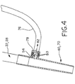
- Fig. 4 shows another example of a separate device in the form of a secondary hose 76.
- the secondary hose 76 can include a connector 78 with internal second threads 80 for attachment to the coupling mechanism 54 as described above.
- the connector 78 and the hose 76 define a passage 82 in fluid communication with the passage 60 of the coupling mechanism 54.
- Fig. 5 illustrates a perspective view of the secondary hose 76 in use.
- the secondary hose 76 provides a remote air intake 84 that can be positioned where necessary in order to draw atmospheric air into the secondary hose and deliver air to the nozzle section.
- the disclosed example illustrated in Figs. 4 and 5 is particularly useful when the liquid level 34 is particularly high.
- the air opening 52, the coupling mechanism 54, and/or the separate attachment can also be provided with an adjustable orifice or air flow controller 90, shown only schematically in the drawings.
- the flow controller can be manipulated to permit full air flow, no air flow or an adjustable air flow through the opening 52.
- the flow controller 90 permits adjustment of the air quantity or volume admitted into the hose, depending on the amount required for a particular collection job to adjust the air/liquid mixture ratio.
- the flow controller can be an adjustable valve, a slidable closure or any other type of suitable device that can be manipulated to open or to partially or completely close off the air flow.
- the controller 90 can also be provided on the distal end of the secondary hose 76, if desired, to remotely control the intake air flow.
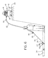
- Fig. 6 is a perspective view of another possible wet/dry vacuum cleaner constructed in accordance with the teachings of the present invention.
- the vacuum cleaner 10 is essentially identical to the vacuum described above with reference to Fig. 1 except for the nozzle section.
- Fig. 6 illustrates a nozzle section 100 that functions similar to a snorkel for providing intake air to the vacuum hose near the media inlet.
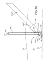
- Fig. 7A illustrates one possible example of the nozzle section 100.
- the nozzle section 100 is removable from the inlet end 26 of the vacuum hose 22 or an inlet end 27 of a hose extension 28.
- the nozzle section 100 generally includes a housing or shell 102 having an exterior wall 104 with an open shell bottom 106 and at least a vertical portion 107 in the wall 104 adjacent the open bottom.
- the vertical portion 107 in the wall permits the media to be collected to enter the shell 102 even when the bottom opening of the section 100 is rested on a surface.
- the open bottom 106 and the vertical portion 107 together define the media inlet of the nozzle section 100 for directing a collected media into the hose 22 or extension 28.
- the nozzle section 100 also has an upstanding elongate tube 108 that, in one disclosed example, extends generally vertically when the nozzle section is properly positioned on or near a surface.
- the tube 108 defines an air passage 110 and has an air intake 112 at a distal end of the tube.
- a proximal end of the tube 108 is attached to the shell 102 and communicates with an opening 114 in the shell. Air enters the intake 112 and travels along the passage 110, exiting the tube at the opening 114 where it enters the nozzle section shell 102.
- the shell 102 defines an interior chamber 116 that is in fluid communication with a connector section 118 of the shell.
- the connector section 118 removably connects the nozzle section 100 to the inlet end 26 of the hose 22 or to the inlet end 27 of a hose extension 28.
- the elongate tube 108 can be formed as an integral part of the shell 102 such as in a one-piece molded construction.
- the elongate tube can be formed as a separate and discrete element that is removably attached to the shell 102.
- the disclosed elongate tube can be provided in several lengths so that a user may attach a tube having an appropriate length for a particular job.
- the elongate tube 108 could also be replaced by a secondary hose such as the hose 76 shown in the prior disclosed example.
- Fig. 7B illustrates an alternative example of a nozzle section 130. All of the components of the section are essentially the same as those shown in the example of Fig. 7A except that the section 130 is integrally formed as part of a hose extension 28 or as part of a vacuum hose 22. An entire vacuum hose and nozzle section can be replaced on the vacuum cleaner 10 when needed for a particular liquid collection job and can be stored when not needed.
- the opening 114 in the shell 102 of either section 100 or 130 can also be provided with a coupling mechanism for receiving a cap to close off the opening or to attach a secondary hose to create a remote air intake as described for the prior example of the nozzle sections 40 and 70.
- a flow controller can be provided on the nozzle sections 100 or 130 for selectively controlling the amount of air admitted into the vacuum hose, also as described above as the flow controller 90. The controller can be added at the shell intake or the distal end of the tube, for example.
- Fig. 8 illustrates an exemplary front view of a nozzle section 100 or 130 illustrating one of many possible configurations of the section including the shell 102.
- the nozzle section can vary considerably in size, shape and configuration.
- the nozzle sections 40 and 70 described previously can also vary considerably in shape, size and configuration as well.
- the materials and manufacturing methods utilized to create the nozzle sections of the invention can also vary considerably and yet fall within the scope of the invention.
- the apparatus and method according to the teachings of the present invention provide a number of significant advantages over a conventional wet/dry vacuum cleaner and also over prior art air mixing apparatuses.
- a conventional wet/dry vacuum cleaner is used to collect liquids by simply immersing the vacuum hose inlet in a liquid and collecting a liquid.
- the liquid lift height of a conventional vacuum cleaner is limited by the applied vacuum provided by the motor and impellers of the machine.
- the vacuum cleaner nozzle sections of the present invention provide a significant increase in the liquid lift height capability without changing any of the major components of the machine.
- a prior art air mixing apparatus such as for the sludge collecting machines described above, includes an air opening disposed above but near the sludge inlet permitting air to enter the hose to somewhat aerate sludge collected in the hose.
- a user must carefully place the inlet end of the hose in the sludge and yet avoid immersing the air opening in the media such as the sludge.
- the nozzle sections described herein permit a user to immerse the nozzle section in the liquid to be collected without paying careful attention to how deep the nozzle is immersed.
- the nozzle sections 40 and 70 that have an attached secondary hose 76 can simply be immersed in the liquid at virtually any depth and even rested on the surface 30.
- the remote air intake will admit air into the hose 76 and hence into the nozzle section regardless of how deep the nozzle section is immersed.
- the nozzle sections 100 and 130 can be rested on a surface 30 as long as the length of the elongate tube 108 extends upward above the top surface 34 of the collected liquid 32.
- the nozzle sections 40 and 70 can also be utilized without a cap or a secondary hose if desired.
- the opening 52 of the air intake will admit air as long as the opening is not immersed in the liquid.
- the nozzle sections 40 and 70 can be adapted to incorporate the separate devices if so desired.
- the nozzle sections 100 and 130 can be utilized without the attached tube or an attached secondary hose as long as the opening 114 in the housing 102 is not immersed in the liquid.
- the air intake in each disclosed example is constructed and arranged to admit air into the vacuum hose when the media inlet is submerged in a liquid.
- the air intake that initially collects air is positioned somewhat remote from the media inlet so that the air intake is exposed to air when the media inlet is immersed to various and possibly substantial liquid depths.
- the air is delivered from the remote intake to the vacuum hose and enters the hose spaced from, but somewhat or relatively adjacent the media inlet so that the air can mix with liquid collected within the vacuum hose at a location that does not prevent the collected liquid within the vacuum hose from being lifted to the tank by the vacuum motor assembly.
- the air delivery point may or may not be the same as the location of the actual remote air intake.
- the air delivery point to the vacuum hose can therefore, for example, essentially be almost directly adjacent or next to the media inlet.
- the air delivery point into the hose can be spaced quite a distance from the media inlet.
- the air delivery point must be at a distance from the media inlet that is less than the maximum pump capacity of the motor assembly.
- the air delivery point into the hose should be less than 50 inches from the media inlet for collecting water. If the air delivery point were 60 inches above the media inlet and the hose orientated vertically, water would only be lifted 50 inches, or 10 inches short of the introduced air. The air would not mix with the collected liquid and the vacuum would fail to lift any liquid to the tank. Therefore, as used herein, the terms “near”, “somewhat adjacent”, “relatively adjacent” or the like can be any value up to the vacuum motor pump capacity.
Landscapes
- Engineering & Computer Science (AREA)
- Mechanical Engineering (AREA)
- Drying Of Solid Materials (AREA)
- Jet Pumps And Other Pumps (AREA)
- Nozzles For Electric Vacuum Cleaners (AREA)
- Cleaning In General (AREA)
- Spinning Methods And Devices For Manufacturing Artificial Fibers (AREA)
Applications Claiming Priority (2)
| Application Number | Priority Date | Filing Date | Title |
|---|---|---|---|
| US09/627,840 US6440227B1 (en) | 2000-07-28 | 2000-07-28 | Nozzle and method providing increased liquid lift height for a wet/dry vacuum cleaner |
| US627840 | 2000-07-28 |
Publications (3)
| Publication Number | Publication Date |
|---|---|
| EP1175862A2 true EP1175862A2 (fr) | 2002-01-30 |
| EP1175862A3 EP1175862A3 (fr) | 2005-05-18 |
| EP1175862B1 EP1175862B1 (fr) | 2009-10-28 |
Family
ID=24516355
Family Applications (1)
| Application Number | Title | Priority Date | Filing Date |
|---|---|---|---|
| EP00403430A Expired - Lifetime EP1175862B1 (fr) | 2000-07-28 | 2000-12-07 | Suceur et procédé pour augmenter la hauteur de transport de liquide pour un aspirateur de poussières a voie humide ou sèche |
Country Status (5)
| Country | Link |
|---|---|
| US (1) | US6440227B1 (fr) |
| EP (1) | EP1175862B1 (fr) |
| AT (1) | ATE446704T1 (fr) |
| CA (1) | CA2330401C (fr) |
| DE (1) | DE60043221D1 (fr) |
Cited By (1)
| Publication number | Priority date | Publication date | Assignee | Title |
|---|---|---|---|---|
| EP3485989A1 (fr) * | 2017-11-20 | 2019-05-22 | PSA Automobiles SA | Dispositif d'aspiration pour produit visqueux |
Families Citing this family (1)
| Publication number | Priority date | Publication date | Assignee | Title |
|---|---|---|---|---|
| US10869586B2 (en) | 2016-11-17 | 2020-12-22 | Karcher North America, Inc. | Portable vacuum and related accessories |
Family Cites Families (14)
| Publication number | Priority date | Publication date | Assignee | Title |
|---|---|---|---|---|
| US683874A (en) | 1900-05-07 | 1901-10-01 | Warren Webster | Means for elevating liquids. |
| AT42445B (de) * | 1909-06-04 | 1910-05-25 | Richard Herz | Mundstück für Apparate zum Absaugen von Staub und Asche. |
| US1106231A (en) * | 1913-06-27 | 1914-08-04 | American Radiator Co | Vacuum-cleaner. |
| US2096595A (en) * | 1936-08-10 | 1937-10-19 | Jack C Sanford | Automatic relief valve for suction pipes |
| US2476425A (en) * | 1945-05-28 | 1949-07-19 | Edward J Mcleary | Fish egg selector |
| US2449596A (en) | 1946-08-20 | 1948-09-21 | Sigge H Ericson | Sludge pumping apparatus |
| US2433408A (en) | 1946-08-30 | 1947-12-30 | George R Tollefsen | Sludge pumping apparatus |
| US3946458A (en) * | 1969-08-22 | 1976-03-30 | Marven Creamer | Apparatus for collecting surface liquids |
| US4023233A (en) | 1975-08-12 | 1977-05-17 | Warwick Pump And Engineering Company Limited | Surface cleaning device |
| US4864681A (en) | 1988-06-20 | 1989-09-12 | Emerson Electric Co. | Multi-purpose floor cleaning tool |
| US5080560A (en) | 1990-02-20 | 1992-01-14 | Leroy Jack W | Dryrite borehole dewatering system |
| EP0501012B1 (fr) | 1991-02-25 | 1997-03-05 | Mitsubishi Jukogyo Kabushiki Kaisha | Pompe de drainage |
| WO1993000852A1 (fr) | 1991-07-03 | 1993-01-21 | Steven Chayer | Procedes et appareil destines a contenir et a evacuer des liquides |
| US5797161A (en) * | 1994-07-12 | 1998-08-25 | Production Metal Forming, Inc. | Nozzle for a fluid vacuum cleaning system |
-
2000
- 2000-07-28 US US09/627,840 patent/US6440227B1/en not_active Expired - Lifetime
- 2000-12-07 DE DE60043221T patent/DE60043221D1/de not_active Expired - Lifetime
- 2000-12-07 AT AT00403430T patent/ATE446704T1/de not_active IP Right Cessation
- 2000-12-07 EP EP00403430A patent/EP1175862B1/fr not_active Expired - Lifetime
-
2001
- 2001-01-08 CA CA002330401A patent/CA2330401C/fr not_active Expired - Fee Related
Cited By (2)
| Publication number | Priority date | Publication date | Assignee | Title |
|---|---|---|---|---|
| EP3485989A1 (fr) * | 2017-11-20 | 2019-05-22 | PSA Automobiles SA | Dispositif d'aspiration pour produit visqueux |
| FR3073757A1 (fr) * | 2017-11-20 | 2019-05-24 | Psa Automobiles Sa | Dispositif d’aspiration pour produit visqueux. |
Also Published As
| Publication number | Publication date |
|---|---|
| HK1045246A1 (en) | 2002-11-22 |
| CA2330401A1 (fr) | 2002-01-28 |
| EP1175862B1 (fr) | 2009-10-28 |
| DE60043221D1 (de) | 2009-12-10 |
| US6440227B1 (en) | 2002-08-27 |
| CA2330401C (fr) | 2008-09-09 |
| EP1175862A3 (fr) | 2005-05-18 |
| ATE446704T1 (de) | 2009-11-15 |
Similar Documents
| Publication | Publication Date | Title |
|---|---|---|
| US4801376A (en) | Cleaner for swimming pools and the like | |
| US4246676A (en) | Liquid collecting vacuum container | |
| US5430910A (en) | Carpet cleaning apparatus | |
| US20070163944A1 (en) | Cleaning apparatus and method | |
| US6119304A (en) | Self-evacuating vacuum cleaner | |
| US20050108836A1 (en) | Portable vacuum cleaning device | |
| US7300576B1 (en) | Pool cleaning system and safety skimmer | |
| EP1143842B1 (fr) | Aspirateur a evacuation automatique et systeme d'amorcage a partir de la sortie de la pompe | |
| US6912757B2 (en) | Vacuum cleaner with continuous liquid pick-up | |
| EP1530664A1 (fr) | Dispositif de nettoyage immerge | |
| US4675936A (en) | Liquid aspirator vacuum attachment | |
| US6440227B1 (en) | Nozzle and method providing increased liquid lift height for a wet/dry vacuum cleaner | |
| HK1045246B (en) | Nozzle and method providing increased liquid lift height for a wet/dry vacuum cleaner | |
| US6637068B2 (en) | Float rod seal for vacuum cleaner | |
| US6513189B1 (en) | Wet attachment apparatus for vacuum cleaners | |
| EP1466551B1 (fr) | Aspirateur à évacuation automatique pour le nettoyage de bassins ou piscines | |
| MXPA01000724A (es) | Boquilla y metodo para proporcionar una elevacion en la altura del liquido para un limpiador de succion en seco/en humedo | |
| US6533833B1 (en) | Method of apparatus for air and liquid vacuuming | |
| DE4447195C1 (de) | Bodenreinigungsmaschine | |
| EP0894467B1 (fr) | Aspirateur comportant une pompe de vidange de liquides | |
| CN2308252Y (zh) | 充气增氧的水族箱过滤器 | |
| CN118892562A (zh) | 一种能同时洗消和排液的洗消设备 | |
| JP3789835B2 (ja) | 水中攪拌装置 | |
| JPS6030822B2 (ja) | 導溝および坑道の清浄装置 | |
| ITMI20000272U1 (it) | Dispositivo aspirapolvere multiuso |
Legal Events
| Date | Code | Title | Description |
|---|---|---|---|
| PUAI | Public reference made under article 153(3) epc to a published international application that has entered the european phase |
Free format text: ORIGINAL CODE: 0009012 |
|
| AK | Designated contracting states |
Kind code of ref document: A2 Designated state(s): AT BE CH CY DE DK ES FI FR GB GR IE IT LI LU MC NL PT SE TR |
|
| AX | Request for extension of the european patent |
Free format text: AL;LT;LV;MK;RO;SI |
|
| PUAL | Search report despatched |
Free format text: ORIGINAL CODE: 0009013 |
|
| AK | Designated contracting states |
Kind code of ref document: A3 Designated state(s): AT BE CH CY DE DK ES FI FR GB GR IE IT LI LU MC NL PT SE TR |
|
| AX | Request for extension of the european patent |
Extension state: AL LT LV MK RO SI |
|
| 17P | Request for examination filed |
Effective date: 20050921 |
|
| AKX | Designation fees paid |
Designated state(s): AT BE CH CY DE DK ES FI FR GB GR IE IT LI LU MC NL PT SE TR |
|
| 17Q | First examination report despatched |
Effective date: 20061018 |
|
| GRAP | Despatch of communication of intention to grant a patent |
Free format text: ORIGINAL CODE: EPIDOSNIGR1 |
|
| GRAS | Grant fee paid |
Free format text: ORIGINAL CODE: EPIDOSNIGR3 |
|
| GRAA | (expected) grant |
Free format text: ORIGINAL CODE: 0009210 |
|
| AK | Designated contracting states |
Kind code of ref document: B1 Designated state(s): AT BE CH CY DE DK ES FI FR GB GR IE IT LI LU MC NL PT SE TR |
|
| REG | Reference to a national code |
Ref country code: GB Ref legal event code: FG4D |
|
| REG | Reference to a national code |
Ref country code: CH Ref legal event code: EP |
|
| REG | Reference to a national code |
Ref country code: IE Ref legal event code: FG4D |
|
| REF | Corresponds to: |
Ref document number: 60043221 Country of ref document: DE Date of ref document: 20091210 Kind code of ref document: P |
|
| REG | Reference to a national code |
Ref country code: CH Ref legal event code: NV Representative=s name: KELLER & PARTNER PATENTANWAELTE AG |
|
| NLV1 | Nl: lapsed or annulled due to failure to fulfill the requirements of art. 29p and 29m of the patents act | ||
| PG25 | Lapsed in a contracting state [announced via postgrant information from national office to epo] |
Ref country code: FI Free format text: LAPSE BECAUSE OF FAILURE TO SUBMIT A TRANSLATION OF THE DESCRIPTION OR TO PAY THE FEE WITHIN THE PRESCRIBED TIME-LIMIT Effective date: 20091028 Ref country code: PT Free format text: LAPSE BECAUSE OF FAILURE TO SUBMIT A TRANSLATION OF THE DESCRIPTION OR TO PAY THE FEE WITHIN THE PRESCRIBED TIME-LIMIT Effective date: 20100301 Ref country code: ES Free format text: LAPSE BECAUSE OF FAILURE TO SUBMIT A TRANSLATION OF THE DESCRIPTION OR TO PAY THE FEE WITHIN THE PRESCRIBED TIME-LIMIT Effective date: 20100208 Ref country code: SE Free format text: LAPSE BECAUSE OF FAILURE TO SUBMIT A TRANSLATION OF THE DESCRIPTION OR TO PAY THE FEE WITHIN THE PRESCRIBED TIME-LIMIT Effective date: 20091028 |
|
| PG25 | Lapsed in a contracting state [announced via postgrant information from national office to epo] |
Ref country code: CY Free format text: LAPSE BECAUSE OF FAILURE TO SUBMIT A TRANSLATION OF THE DESCRIPTION OR TO PAY THE FEE WITHIN THE PRESCRIBED TIME-LIMIT Effective date: 20091028 |
|
| PG25 | Lapsed in a contracting state [announced via postgrant information from national office to epo] |
Ref country code: BE Free format text: LAPSE BECAUSE OF FAILURE TO SUBMIT A TRANSLATION OF THE DESCRIPTION OR TO PAY THE FEE WITHIN THE PRESCRIBED TIME-LIMIT Effective date: 20091028 Ref country code: AT Free format text: LAPSE BECAUSE OF FAILURE TO SUBMIT A TRANSLATION OF THE DESCRIPTION OR TO PAY THE FEE WITHIN THE PRESCRIBED TIME-LIMIT Effective date: 20091028 |
|
| PG25 | Lapsed in a contracting state [announced via postgrant information from national office to epo] |
Ref country code: DK Free format text: LAPSE BECAUSE OF FAILURE TO SUBMIT A TRANSLATION OF THE DESCRIPTION OR TO PAY THE FEE WITHIN THE PRESCRIBED TIME-LIMIT Effective date: 20091028 Ref country code: MC Free format text: LAPSE BECAUSE OF NON-PAYMENT OF DUE FEES Effective date: 20100701 |
|
| REG | Reference to a national code |
Ref country code: HK Ref legal event code: GR Ref document number: 1045246 Country of ref document: HK |
|
| PLBE | No opposition filed within time limit |
Free format text: ORIGINAL CODE: 0009261 |
|
| STAA | Information on the status of an ep patent application or granted ep patent |
Free format text: STATUS: NO OPPOSITION FILED WITHIN TIME LIMIT |
|
| 26N | No opposition filed |
Effective date: 20100729 |
|
| PG25 | Lapsed in a contracting state [announced via postgrant information from national office to epo] |
Ref country code: GR Free format text: LAPSE BECAUSE OF FAILURE TO SUBMIT A TRANSLATION OF THE DESCRIPTION OR TO PAY THE FEE WITHIN THE PRESCRIBED TIME-LIMIT Effective date: 20100129 |
|
| PGFP | Annual fee paid to national office [announced via postgrant information from national office to epo] |
Ref country code: IE Payment date: 20101214 Year of fee payment: 11 |
|
| PGFP | Annual fee paid to national office [announced via postgrant information from national office to epo] |
Ref country code: CH Payment date: 20101215 Year of fee payment: 11 |
|
| PGFP | Annual fee paid to national office [announced via postgrant information from national office to epo] |
Ref country code: IT Payment date: 20101218 Year of fee payment: 11 Ref country code: GB Payment date: 20101201 Year of fee payment: 11 |
|
| PG25 | Lapsed in a contracting state [announced via postgrant information from national office to epo] |
Ref country code: LU Free format text: LAPSE BECAUSE OF NON-PAYMENT OF DUE FEES Effective date: 20091207 |
|
| PG25 | Lapsed in a contracting state [announced via postgrant information from national office to epo] |
Ref country code: TR Free format text: LAPSE BECAUSE OF FAILURE TO SUBMIT A TRANSLATION OF THE DESCRIPTION OR TO PAY THE FEE WITHIN THE PRESCRIBED TIME-LIMIT Effective date: 20091028 |
|
| REG | Reference to a national code |
Ref country code: CH Ref legal event code: PL |
|
| GBPC | Gb: european patent ceased through non-payment of renewal fee |
Effective date: 20111207 |
|
| REG | Reference to a national code |
Ref country code: IE Ref legal event code: MM4A |
|
| PG25 | Lapsed in a contracting state [announced via postgrant information from national office to epo] |
Ref country code: NL Free format text: LAPSE BECAUSE OF FAILURE TO SUBMIT A TRANSLATION OF THE DESCRIPTION OR TO PAY THE FEE WITHIN THE PRESCRIBED TIME-LIMIT Effective date: 20091028 |
|
| PG25 | Lapsed in a contracting state [announced via postgrant information from national office to epo] |
Ref country code: CH Free format text: LAPSE BECAUSE OF NON-PAYMENT OF DUE FEES Effective date: 20111231 Ref country code: GB Free format text: LAPSE BECAUSE OF NON-PAYMENT OF DUE FEES Effective date: 20111207 Ref country code: IE Free format text: LAPSE BECAUSE OF NON-PAYMENT OF DUE FEES Effective date: 20111207 Ref country code: LI Free format text: LAPSE BECAUSE OF NON-PAYMENT OF DUE FEES Effective date: 20111231 |
|
| PG25 | Lapsed in a contracting state [announced via postgrant information from national office to epo] |
Ref country code: IT Free format text: LAPSE BECAUSE OF NON-PAYMENT OF DUE FEES Effective date: 20111207 |
|
| REG | Reference to a national code |
Ref country code: FR Ref legal event code: PLFP Year of fee payment: 16 |
|
| REG | Reference to a national code |
Ref country code: FR Ref legal event code: PLFP Year of fee payment: 17 |
|
| REG | Reference to a national code |
Ref country code: FR Ref legal event code: PLFP Year of fee payment: 18 |
|
| PGFP | Annual fee paid to national office [announced via postgrant information from national office to epo] |
Ref country code: DE Payment date: 20171129 Year of fee payment: 18 Ref country code: FR Payment date: 20171113 Year of fee payment: 18 |
|
| REG | Reference to a national code |
Ref country code: DE Ref legal event code: R119 Ref document number: 60043221 Country of ref document: DE |
|
| PG25 | Lapsed in a contracting state [announced via postgrant information from national office to epo] |
Ref country code: FR Free format text: LAPSE BECAUSE OF NON-PAYMENT OF DUE FEES Effective date: 20181231 Ref country code: DE Free format text: LAPSE BECAUSE OF NON-PAYMENT OF DUE FEES Effective date: 20190702 |