EP1175961A2 - Procédé et dispositif pour usiner les surfaces de pièces - Google Patents
Procédé et dispositif pour usiner les surfaces de pièces Download PDFInfo
- Publication number
- EP1175961A2 EP1175961A2 EP01117029A EP01117029A EP1175961A2 EP 1175961 A2 EP1175961 A2 EP 1175961A2 EP 01117029 A EP01117029 A EP 01117029A EP 01117029 A EP01117029 A EP 01117029A EP 1175961 A2 EP1175961 A2 EP 1175961A2
- Authority
- EP
- European Patent Office
- Prior art keywords
- tools
- tool
- machining
- tool unit
- frame
- Prior art date
- Legal status (The legal status is an assumption and is not a legal conclusion. Google has not performed a legal analysis and makes no representation as to the accuracy of the status listed.)
- Withdrawn
Links
Images

Classifications
-
- B—PERFORMING OPERATIONS; TRANSPORTING
- B24—GRINDING; POLISHING
- B24B—MACHINES, DEVICES, OR PROCESSES FOR GRINDING OR POLISHING; DRESSING OR CONDITIONING OF ABRADING SURFACES; FEEDING OF GRINDING, POLISHING, OR LAPPING AGENTS
- B24B29/00—Machines or devices for polishing surfaces on work by means of tools made of soft or flexible material with or without the application of solid or liquid polishing agents
- B24B29/005—Machines or devices for polishing surfaces on work by means of tools made of soft or flexible material with or without the application of solid or liquid polishing agents using brushes
-
- B—PERFORMING OPERATIONS; TRANSPORTING
- B24—GRINDING; POLISHING
- B24B—MACHINES, DEVICES, OR PROCESSES FOR GRINDING OR POLISHING; DRESSING OR CONDITIONING OF ABRADING SURFACES; FEEDING OF GRINDING, POLISHING, OR LAPPING AGENTS
- B24B41/00—Component parts such as frames, beds, carriages, headstocks
- B24B41/04—Headstocks; Working-spindles; Features relating thereto
- B24B41/047—Grinding heads for working on plane surfaces
-
- B—PERFORMING OPERATIONS; TRANSPORTING
- B24—GRINDING; POLISHING
- B24B—MACHINES, DEVICES, OR PROCESSES FOR GRINDING OR POLISHING; DRESSING OR CONDITIONING OF ABRADING SURFACES; FEEDING OF GRINDING, POLISHING, OR LAPPING AGENTS
- B24B7/00—Machines or devices designed for grinding plane surfaces on work, including polishing plane glass surfaces; Accessories therefor
- B24B7/06—Machines or devices designed for grinding plane surfaces on work, including polishing plane glass surfaces; Accessories therefor involving conveyor belts, a sequence of travelling work-tables or the like
-
- B—PERFORMING OPERATIONS; TRANSPORTING
- B24—GRINDING; POLISHING
- B24D—TOOLS FOR GRINDING, BUFFING OR SHARPENING
- B24D13/00—Wheels having flexibly-acting working parts, e.g. buffing wheels; Mountings therefor
- B24D13/02—Wheels having flexibly-acting working parts, e.g. buffing wheels; Mountings therefor acting by their periphery
- B24D13/10—Wheels having flexibly-acting working parts, e.g. buffing wheels; Mountings therefor acting by their periphery comprising assemblies of brushes
Definitions
- the invention relates to a method and an apparatus for processing surfaces of essentially flat workpieces, according to the generic term of claim 1 or according to the preamble of Claim 12.
- Such methods and devices are used both for relatively large as well as for relatively small workpiece surfaces, for example for cleaning, grinding and Polishing the surfaces themselves as well as deburring from outside and inside edges of in any Cut out or punched out flat Workpieces used, for example made of sheet metal, Wood-based materials, plastics and the like manufactured could be.
- the invention has for its object a method according to the preamble of claim 1 and a device according to the preamble of claim 12 so that the processing device at relative low device effort and with optimal Machining result extremely reliable for very diverse Surface processing types can be used can.
- a basic idea of the method according to the invention becomes seen in that the workpiece surfaces in at least a processing zone of the same processing device optionally by means of at least one processing roller containing first tool unit or one a group of plate-shaped processing tools containing second tool unit processed be, the processing roller approximately in its radial Direction and the plate-shaped editing tools approximately in their axial direction against the Workpiece surfaces.
- the inventive method are in the first tool unit a brush roller and in the second tool unit as plate-shaped processing tools adjustable against the workpiece surface Disc brushes used.
- Brush-shaped editing tools have proven themselves in practical use proven to be particularly versatile, with additional it should be noted that on the one hand the brush rollers and the plate brushes each for quite different ones Editing interventions are suitable and that to the other in addition there is the possibility of both specific for brush rollers as well as for plate brushes to use adapted bristle material (bristle trim), for more or less intensive editing to be able to generate.
- the device designed according to the invention draws is characterized in that for at least one processing zone this device has at least one processing roller containing first tool unit and one at least one group of plate-shaped processing tools containing second tool unit provided and these tool units optionally for processing the workpiece surfaces are operable, whereby the processing roller with its outer peripheral surface in about radial direction and the plate-shaped processing tools with their outer faces roughly adjustable in the axial direction against the workpiece surfaces are.
- Each tool unit has its own device Tool storage frame for arrangement and mounting of the editing tools on and it's one Quick change device for optional mutual Exchange of the various tool units provided each tool storage frame in its Shape and similar in its outer dimensions is designed so that it fits exactly in the same Sub-frame of the main device frame fixed but interchangeable.
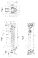
- FIGS. 1 to 3 The overall structure of the processing device according to the invention 1 is first explained with reference to FIGS. 1 to 3, adding that there essentially - in a partially simplified form - only the device parts are illustrated to illustrate the invention be considered necessary.
- This processing device 1 is used for processing of surfaces 2a of any, essentially flat Workpieces 2 (e.g. made of sheet metal, wood materials, Plastics and the like), which during their processing on a suitable transport device, for example a conveyor belt only indicated in Fig.1 3 for example in the direction of arrow 4 (Fig.2) below one or more processing tools each installed tool unit transported along become.
- a suitable transport device for example a conveyor belt only indicated in Fig.1 3 for example in the direction of arrow 4 (Fig.2) below one or more processing tools each installed tool unit transported along become.
- a first tool unit 5 in which a brush roller 6 as a processing roller or roller-shaped processing tool is arranged to be driven in rotation.
- the brush roller can be explained in more detail 6 - as known in principle - with your Outer peripheral surface in approximately the radial direction against the Workpiece surface 2a set or lifted off become, i.e. the brush roller 6 is with the entire first tool unit 5 in the direction of the double arrow 7, that is, in the vertical direction, to a sufficient extent and precisely adjustable.
- the processing device 1 includes a main device frame 8, in which a main frame 9 with the help of two adjustment gears (e.g. worm gears) 10 and associated adjusting spindles 11 in the vertical direction and is therefore adjustable in height to ensure vertical adjustability or starting the respective tools (e.g. brush roller 6) according to double arrow 7 to guarantee against the workpiece surfaces 2a can.
- the adjusting spindles 11 can approximately in Hollow shafts of the adjustment gear 10 axially adjustable his. This axial adjustment (and thus the Height adjustment of the main frame 9 with it arranged device parts) can by any suitable Drive device happen; in this embodiment Air cylinders 12 are provided for this purpose.
- the axial adjustment path can also by suitable and preferably adjustable stops 13 (Fig.2) can be limited.
- the axial adjustment explained above can be used to a certain extent as a double axial adjustment and thus as double height adjustment in the direction of the double arrow be carried out in such a way that in each case in the main device frame 8 built-in editing tools (Brush roller 6 or those to be explained later Disc brushes 25) on at least two adjustment paths vertically adjusted relative to the tool surfaces 2a can be, of which the first adjustment is the general Adjustability and adjustability and the second Adjustment path forms a predeterminable stroke size by which the machining tools from the workpiece surfaces 2a raised to an inactive disengaged position become.
- the first adjustment is the general Adjustability and adjustability
- the second Adjustment path forms a predeterminable stroke size by which the machining tools from the workpiece surfaces 2a raised to an inactive disengaged position become.
- the machining tools can be preset with the stroke size with the help of the adjustment gear 10 and the associated Adjustment spindles 11 via the first adjustment path with sufficiently large adjustment dimensions any general be employed or adjusted if necessary (e.g. with different workpiece thicknesses, after wear of the bristle trimmings of the processing tools etc.).
- a swing frame 14 is also arranged in the main frame 9, the one at the ends by longitudinal guide pins 15 or the like in fixed guide bushings 16 in Direction of dashed double arrow 17 for one approximately across the workpiece 2 or its direction of transport stored back and forth movement according to arrow 4 is, i.e. this swing frame 14 can be a corresponding one transverse reciprocating relative movement between the workpieces 2 and the tools (e.g. roller 6).
- Swing frame 14 on the main frame 9 a suitable Assigned oscillation drive 18, which u.a. a drive motor 18a, an angular gear 18b and a crank mechanism 18c can contain.
- a suitable oscillation drive 18 which u.a. a drive motor 18a, an angular gear 18b and a crank mechanism 18c can contain.
- you could other suitable oscillation drives are also provided be such as a pneumatic cylinder or an electric cylinder.
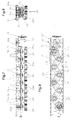
- FIG. 4 referred to 6, in which only the first tool unit 5 illustrated in different views is.
- this first tool unit 5 like any tool unit of the machining device 1 - its own tool storage frame 19 for arrangement, mounting and pivoting of the associated processing tool, i.e. in in this case the brush roller 6.
- the brush roller 6 is over their shaft ends 6a, 6b in two on this face Storage frame 19 hanging bearings attached down 20 rotatably mounted. That beyond the camp 20 extended a shaft end 6b of the brush roller 6 carries a non-rotatably attached drive wheel, which preferably in the form of a pulley or V-belt pulley 21 is formed.
- a non-rotatably attached drive wheel which preferably in the form of a pulley or V-belt pulley 21 is formed.
- this processing device 1 as an important feature a quick change device for optional mutual exchange which contains various tool units.
- the tool storage frame each tool unit of the machining device 1 the tool storage frame of all tool units in their shape and in their external dimensions are of the same design and belong to the other also a sub-frame of the main device frame 8, this receiving subframe like this is executed that every tool storage frame fits exactly in it of the different tool units the processing device 1 fixed, but replaceable can be installed.
- This tool storage frame 19 itself has essentially the shape of an elongated regular Rectangle of sufficient length.
- the first tool unit 5 (as well any other tool unit that can be installed there) during of the machining company, on the one hand, directly or permanently with the swing frame 14 and the other - about this Swing frame 14 - also firmly connected to the main frame 9, so this tool unit 5 - and any other firmly connected tool unit - both the Oscillating movements (double arrow 17) of the swing frame 14 as well as the vertical adjustment or adjustment movements (Double arrow 7) of the main frame 9.
- the lower ones are Ends of the swing frame 14 in the form of bends 14a - pointing inwards - bent inwards, see above that they the side members 19a of the tool storage frame 19 reach under, these bends at 14a their upward-facing sides in the form of slide rails (if necessary or appropriate with sliding material pads) are trained. If now the screws 22 out the tool storage frame 19 are unscrewed and the latter or the associated tool unit 5 is in the released state, then supports this tool storage frame 19 via its side members 19a accordingly on the bends or slide rails 14a.
- this first Tool unit 5 is the V-belt pulley 21 of the brush roller 6 in the area of one end the processing device 1. Accordingly, in suitably in or on the main device frame 8 for the rotary drive of this brush roller 6 one Drive device 23 fixedly attached by a drive connection, preferably a belt drive or V-belt drive 24 with the drive wheel or V-belt pulley 21 installed in the swing frame 14 first tool unit 5 (or any other built-in tool unit) in drive connection stands.
- a drive connection preferably a belt drive or V-belt drive 24 with the drive wheel or V-belt pulley 21 installed in the swing frame 14 first tool unit 5 (or any other built-in tool unit) in drive connection stands.
- the drive device 23 or a corresponding one Drive motor can generally be customized for an overall Drive speed of the brush roller 6 designed his; however, it can be particularly useful if this drive device 23 with a speed control is equipped so that the different Machining tools with those considered to be optimal Rotation speeds (also in adaptation to different materials) can be driven. there it can also be particularly advantageous if the drive device 23 is designed so that the each processing tool used (be it a Brush roller 6 or more, be it plate-shaped Machining tools / disc brushes, as explained in more detail if necessary, with reversible direction of rotation can be driven.
- a special feature of this processing device according to the invention 1 can generally be seen in the fact that one or each (if there are several of the same type and series-connected) processing zone this device 1 has at least one processing roller or brush roller 6 containing the first tool unit 5 and at least one group of plate-shaped Second machining tools Tool unit provided and these tool units optional, i.e. interchangeable for processing the workpiece surfaces 2a in the device 1 can be operated.
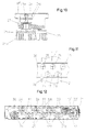
- this tool storage frame 19 ' the second tool unit 30 in the form of an elongated one regular rectangle, not only its shape, but also its external dimensions are the same or the same size as those of the tool storage frame 19 of the first tool unit 5.
- This tool storage frame 19 '- how 8 and 10 in particular clarify - pronounced and longitudinal members 19'a which can be freely gripped from the outside on, so that this tool storage frame 19 'in turn fits exactly into the same mounting subframe, So the swing frame 14 of the main device frame 8 fixed but interchangeable, in exactly the same way as above in Connection with the tool storage frame 19 of the first tool unit 5 (in particular with reference to FIG. 2) in the individual has been explained, what to avoid be referred from repetitions.
- Embodiment of the second tool unit 30 is provided that the plate brushes 25 on their as brush shafts 26 trained rotating shafts individually in the tool storage frame 19 'for example with the help of Rolling bearings 27 in the manner illustrated in Fig.10 are rotatably mounted.
- Two adjacent to each other Brush shafts 26 are on their plate brushes 25 opposite shaft ends 26a by a drive connection connected to each other with the drive first embodiment of the second tool unit 30 by a belt drive, preferably one Toothed belt drive 31 is formed.
- These are - as in particular 7 and 10 show - on the upper shaft ends 26a of the brush shafts 26 generally each two corresponding toothed belt pulleys 31a axially directly one above the other or a corresponding double disc non-rotatably attached.
- This angular gear 32 is thus - as shown in Figure 7 in particular - between the associated V-belt pulley 21 and the corresponding first tool-drive connection, i.e. the neighboring one Toothed belt drive 31 arranged, on this connection a further toothed belt drive 32a is provided (Fig. 7 and 9).
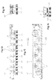
- Disc brushes 25 - viewed in plan - about are staggered to each other and that they are at least in relation to the workpiece transport direction (Arrow 4), but preferably also, as shown, overlap each other in the transverse direction.
- This evenly overlapping arrangement the plate brushes 25 can do this among them workpiece 2 transported through on its surface 2a of the plate brushes 25 or their brush trimmings 25a can be optimally processed.
- This brush plate assembly basically also applies to the following further described embodiments the second tool unit.
- each plate brush 25 assigned a separate drive motor 34 is, it is preferred, each drive motor 34 to be equipped with a separate speed control.
- the individual plate brushes 25 can on the downwardly projecting ends of the motor drive shafts 34a be attached so that the plate brushes 25 then again driven to rotate about vertical axes of rotation can be.
- the disc brushes 25 with their single drive motors 34 in its own tool carrier frame 19 'recorded and supported the shape and External dimensions to those of the above based on approximately the Fig. 7-10 described tool support frame 19 'correspond.
- the plate brushes 25 can all with of the same kind or individually or in groups with different ones Rotational speeds are driven.
- these plate brushes 25 are then infinitely adjustable Rotational speeds are driven, it also can also be an advantage if these plate brushes 25 optionally in one or the other direction of rotation can be driven, namely all plate brushes 25 each in one or the other direction of rotation or directed against each other individually or in groups.
- Disc brushes 25 individually, in groups or together against the workpiece surface 2a. This is for example, advantageous if the bristle trim 25a of the plate brushes worn to a certain extent is, i.e. there is the possibility of the plate brushes 25 according to their respective wear by an adjusted Readjustment.
- the surfaces according to this embodiment of the invention 2a of workpieces 2 in one and the same processing device 1 optionally by means of at least one Processing roller, preferably a brush roller 6 containing first tool unit 5 or - in exchange to do this - by means of a group of plate-shaped Processing tools, preferably disc brushes 25 containing second tool unit 30 machined become. It is then in each case corresponding Way, the brush roller 6 approximately in its radial Direction against the workpiece surfaces 2a, while the plate brushes 25 approximately in their axial Direction against the workpiece surfaces 2a are, in each case according to the double arrow 7 1 and 2.
- the workpieces 2 are then during processing their surfaces 2a with the help of Transport device 3 in the longitudinal direction under the processing tools, So the brush roller 6 or under transported along the plate brushes 25. Are there then the workpieces 2 are sufficiently firm or stationary deposited on the transport device 3, with it With the help of this transport device 3 continuously as required, batchwise or reversible relative to the processing tools are transported.
Landscapes
- Engineering & Computer Science (AREA)
- Mechanical Engineering (AREA)
- Finish Polishing, Edge Sharpening, And Grinding By Specific Grinding Devices (AREA)
- Turning (AREA)
Priority Applications (1)
| Application Number | Priority Date | Filing Date | Title |
|---|---|---|---|
| DE20122200U DE20122200U1 (de) | 2000-07-24 | 2001-07-12 | Vorrichtung zur Bearbeitung von Werkstückoberflächen |
Applications Claiming Priority (2)
| Application Number | Priority Date | Filing Date | Title |
|---|---|---|---|
| DE10035977 | 2000-07-24 | ||
| DE10035977A DE10035977A1 (de) | 2000-07-24 | 2000-07-24 | Verfahren und Vorrichtung zur Bearbeitung von Werkstück-Oberflächen |
Publications (2)
| Publication Number | Publication Date |
|---|---|
| EP1175961A2 true EP1175961A2 (fr) | 2002-01-30 |
| EP1175961A3 EP1175961A3 (fr) | 2003-12-17 |
Family
ID=7650013
Family Applications (1)
| Application Number | Title | Priority Date | Filing Date |
|---|---|---|---|
| EP01117029A Withdrawn EP1175961A3 (fr) | 2000-07-24 | 2001-07-12 | Procédé et dispositif pour usiner les surfaces de pièces |
Country Status (3)
| Country | Link |
|---|---|
| US (1) | US20020068515A1 (fr) |
| EP (1) | EP1175961A3 (fr) |
| DE (1) | DE10035977A1 (fr) |
Cited By (10)
| Publication number | Priority date | Publication date | Assignee | Title |
|---|---|---|---|---|
| EP1384552A1 (fr) * | 2002-07-26 | 2004-01-28 | DuBois Equipment Company, Inc. | Machine de ponçage pour la finition de produits en bois |
| EP1477275A1 (fr) * | 2003-05-12 | 2004-11-17 | Slipcon Holding International ApS | Machine d'usinage par abrasion à meules susceptibles de se déplacer à mouvement de va-et-vient de manière transversale vers l'article |
| WO2004098831A1 (fr) * | 2003-05-12 | 2004-11-18 | Slipcon Holding International Aps | Machine abrasive presentant des disques abrasifs qui sont deplaces par un mouvement reciproque transversal par rapport a l'article a abraser |
| WO2007095947A1 (fr) * | 2006-02-22 | 2007-08-30 | Amanda Patent & Licensing Sia | Module brosse |
| EP2796242A3 (fr) * | 2013-04-22 | 2014-11-26 | Arku Maschinenbau GmbH | Machine d'ébavurage et son procédé de réglage |
| ITRM20130453A1 (it) * | 2013-08-01 | 2015-02-02 | Scm Group Spa | Apparecchiatura di lavorazione a dischi rotativi perfezionata e relativo modulo di lavorazione. |
| DK178121B1 (da) * | 2014-06-20 | 2015-06-01 | Flex Trim As | Slibemaskine med slibehoveder på mindst to bevægelige slæder |
| WO2016000819A1 (fr) * | 2014-07-01 | 2016-01-07 | Karl Heesemann Maschinenfabrik Gmbh & Co. Kg | Machine de rectification d'une surface d'une pièce |
| CN113167346A (zh) * | 2019-01-11 | 2021-07-23 | 大陆-特韦斯贸易合伙股份公司及两合公司 | 用于机动车辆的罐状的复合制动盘 |
| EP3928923A1 (fr) * | 2020-06-16 | 2021-12-29 | Schindler GmbH | Dispositif et procédé de traitement de la surface d'une surface en roche ou en béton |
Families Citing this family (13)
| Publication number | Priority date | Publication date | Assignee | Title |
|---|---|---|---|---|
| DK200301826A (da) * | 2003-12-10 | 2005-06-11 | Flex Trim As | Slibeapparat til behandling af en flade |
| DE202005006412U1 (de) * | 2004-05-27 | 2005-06-30 | Battenfeld Extrusionstechnik Gmbh | Kühlvorrichtung |
| DE102007031656A1 (de) * | 2007-07-06 | 2009-01-08 | Heesemann, Jürgen, Dipl.-Ing. | Schleifmaschine |
| DE102010026903A1 (de) | 2010-07-12 | 2012-01-12 | Amw Gmbh | Transdermales therapeutisches System mit Avocadoöl oder Palmöl als Hilfsstoff |
| CN102179762B (zh) * | 2011-04-06 | 2013-03-27 | 浙江金圣竹木有限公司 | 菜板润色抛光机 |
| CN102581714B (zh) * | 2012-03-06 | 2014-01-15 | 珠海镇东有限公司 | 一种磨板机的自动整刷装置 |
| ES2600755B1 (es) * | 2015-08-10 | 2018-03-02 | Calvet Brothers, S.L. | Filamento de acero, cepillo pulidor que comprende el mismo y dispositivo pulidor que comprende una plurlidad de cepillos pulidores y uso de los mismos |
| DE102015010612A1 (de) * | 2015-08-18 | 2017-02-23 | Wöhler Brush Tech GmbH | Vorrichtung und Verfahren der Oberflächenbearbeitung von Werkstücken |
| IT201900024631A1 (it) * | 2019-12-19 | 2021-06-19 | Biesse Spa | Macchina sbavatrice per la finitura di elementi di legno, metallo, materiale plastico o simili |
| CN112775756B (zh) * | 2021-01-28 | 2022-07-29 | 中国核动力研究设计院 | 稳压器电加热元件套管孔内打磨装置 |
| CN113275962B (zh) * | 2021-06-16 | 2022-10-25 | 江西和美陶瓷有限公司 | 陶瓷砖吸水率检测样品的预处理装置及其控制方法 |
| CN117226442B (zh) * | 2023-11-01 | 2024-05-07 | 东莞市彼联机械科技有限公司 | 一种用于工件矫形的数控设备 |
| CN120516512B (zh) * | 2025-06-12 | 2026-03-20 | 兴化市佳谕不锈钢有限公司 | 一种不锈钢加工用轧辊打磨抛光装置 |
Family Cites Families (6)
| Publication number | Priority date | Publication date | Assignee | Title |
|---|---|---|---|---|
| US2635653A (en) * | 1950-07-27 | 1953-04-21 | Charles H Hennell | Apparatus for embossing graining of wood |
| US2989823A (en) * | 1959-03-09 | 1961-06-27 | Merit Products Inc | Finishing machine with reciprocative rotary finishing roll |
| DE2304439A1 (de) * | 1973-01-30 | 1974-08-01 | Rosner Ohg L | Vorrichtung zum profilbuersten einer holzflaeche |
| US4078905A (en) * | 1976-12-03 | 1978-03-14 | Mitsubishi Jukogyo Kabushiki Kaisha | Edge-rounding method and apparatus therefor |
| NL7904403A (nl) * | 1979-06-05 | 1980-12-09 | Linden Bv Machine | Inrichting voor oppervlak-bewerking van voorwerpen. |
| US5105583A (en) * | 1990-08-29 | 1992-04-21 | Hammond Machinery Inc. | Workpiece deburring method and apparatus |
-
2000
- 2000-07-24 DE DE10035977A patent/DE10035977A1/de not_active Withdrawn
-
2001
- 2001-07-12 EP EP01117029A patent/EP1175961A3/fr not_active Withdrawn
- 2001-07-21 US US09/909,749 patent/US20020068515A1/en not_active Abandoned
Cited By (14)
| Publication number | Priority date | Publication date | Assignee | Title |
|---|---|---|---|---|
| EP1384552A1 (fr) * | 2002-07-26 | 2004-01-28 | DuBois Equipment Company, Inc. | Machine de ponçage pour la finition de produits en bois |
| DK178219B1 (da) * | 2003-05-12 | 2015-08-31 | Slipcon Holding Internat Aps | Slibemaskine med roterende slibeskiver, der bevæges i en frem- og tilbagegående bevægelse på tværs af emnet |
| EP1477275A1 (fr) * | 2003-05-12 | 2004-11-17 | Slipcon Holding International ApS | Machine d'usinage par abrasion à meules susceptibles de se déplacer à mouvement de va-et-vient de manière transversale vers l'article |
| WO2004098831A1 (fr) * | 2003-05-12 | 2004-11-18 | Slipcon Holding International Aps | Machine abrasive presentant des disques abrasifs qui sont deplaces par un mouvement reciproque transversal par rapport a l'article a abraser |
| WO2007095947A1 (fr) * | 2006-02-22 | 2007-08-30 | Amanda Patent & Licensing Sia | Module brosse |
| EP2796242A3 (fr) * | 2013-04-22 | 2014-11-26 | Arku Maschinenbau GmbH | Machine d'ébavurage et son procédé de réglage |
| ITRM20130453A1 (it) * | 2013-08-01 | 2015-02-02 | Scm Group Spa | Apparecchiatura di lavorazione a dischi rotativi perfezionata e relativo modulo di lavorazione. |
| DK178121B1 (da) * | 2014-06-20 | 2015-06-01 | Flex Trim As | Slibemaskine med slibehoveder på mindst to bevægelige slæder |
| WO2016000819A1 (fr) * | 2014-07-01 | 2016-01-07 | Karl Heesemann Maschinenfabrik Gmbh & Co. Kg | Machine de rectification d'une surface d'une pièce |
| DE102014009582A1 (de) | 2014-07-01 | 2016-01-07 | Karl Heesemann Maschinenfabrik Gmbh & Co Kg | Schleifmaschine zum Schleifen einer Oberfläche eines Werkstückes |
| CN113167346A (zh) * | 2019-01-11 | 2021-07-23 | 大陆-特韦斯贸易合伙股份公司及两合公司 | 用于机动车辆的罐状的复合制动盘 |
| US11885384B2 (en) | 2019-01-11 | 2024-01-30 | Continental Teves Ag & Co. Ohg | Pot-shaped composite brake rotor for motor vehicles |
| CN113167346B (zh) * | 2019-01-11 | 2024-03-08 | 大陆汽车科技有限公司 | 用于机动车辆的罐状的复合制动盘 |
| EP3928923A1 (fr) * | 2020-06-16 | 2021-12-29 | Schindler GmbH | Dispositif et procédé de traitement de la surface d'une surface en roche ou en béton |
Also Published As
| Publication number | Publication date |
|---|---|
| DE10035977A1 (de) | 2002-02-07 |
| EP1175961A3 (fr) | 2003-12-17 |
| US20020068515A1 (en) | 2002-06-06 |
Similar Documents
| Publication | Publication Date | Title |
|---|---|---|
| DE10035977A1 (de) | Verfahren und Vorrichtung zur Bearbeitung von Werkstück-Oberflächen | |
| DE3416664C2 (de) | Einrichtung zum Steuern der Schneidgeschwindigkeit des Sägeblattes einer Bandsägemaschine | |
| DE9414501U1 (de) | Bearbeitungsmaschine mit relativverschiebbaren Drehvorrichtungen | |
| DE2311011A1 (de) | Kopierschleifmaschine fuer werkstuecke aus holz oder kunststoff mit unregelmaessiger koerperform | |
| DE202009019024U1 (de) | Bearbeitungsstation und Vorrichtung zum Bearbeiten eines Werkstücks | |
| EP1068917A2 (fr) | Dispositif et methode d' usinage de manetons de vilebrequins | |
| DE19723306C2 (de) | Verfahren und Vorrichtung zum Schleifen oder Polieren von Stirnflächen plattenförmiger Körper | |
| EP1314513A2 (fr) | Procédé pour l'ébavurage de plaques de verre | |
| DE60304179T2 (de) | Schleifmaschine | |
| DE69803238T2 (de) | Abrichtmaschine | |
| DE8806552U1 (de) | Maschine zum Entgraten von Werkstücken | |
| DE102021105394A1 (de) | Aggregat zum Entgraten und Verrunden von Kanten in einer Flächenschleifmaschine | |
| DE3335430A1 (de) | Schneidapparat | |
| DE69316776T2 (de) | Schneidmaschine ausgerüstet mit einem rotierenden rundschneidmesser zum schneiden eines biegsamen materials in form eines einzelnen blattes oder eines kleinen blattstapels, sowie verfahren zur einstellung einer solchen maschine | |
| DE19808804C2 (de) | Maschine zur Oberflächenbearbeitung mindestens einer textilen Warenbahn, insbesondere zum Rauhen und/oder Schmirgeln od. dgl. | |
| DE19821982C2 (de) | Profil-Bandschleifmaschine | |
| EP1043087B1 (fr) | Machine de rectification et de durcissement pour arbres | |
| DE2151218A1 (de) | Verfahren und Vorrichtung zum Stanzen von Fenstern in Rohlinge aus blattfoermigem Material | |
| DE102004043157A1 (de) | Verfahren und Vorrichtung zur Schleifbearbeitung eines Schneidwerkzeuges, insbesondere eines Messers | |
| DE20122200U1 (de) | Vorrichtung zur Bearbeitung von Werkstückoberflächen | |
| DE69802237T2 (de) | Vorrichtung zum Schleifen von gekerbten Schneidkanten auf Messerbändern | |
| DE2551804C3 (de) | Vorrichtung zum Anfasen oder Anspitzen .von jeweils aus einem zylindrischen Schaft mit einem Kopf bestehenden Werkstücken | |
| DE3430065C2 (de) | Entgratmaschine zur Endenbearbeitung von Zylindrischen Werkstücken wie Rohre, Stangen oder dergleichen | |
| DE4000251A1 (de) | Rotor an einer vorrichtung zum bearbeiten der oberflaeche von draehten und staeben durch schleifen | |
| EP3369685A1 (fr) | Dispositif de transport de pièces allongées à un point de réception et de dépôt des dites pièces allongées audit point de réception |
Legal Events
| Date | Code | Title | Description |
|---|---|---|---|
| PUAI | Public reference made under article 153(3) epc to a published international application that has entered the european phase |
Free format text: ORIGINAL CODE: 0009012 |
|
| AK | Designated contracting states |
Kind code of ref document: A2 Designated state(s): AT BE CH CY DE DK ES FI FR GB GR IE IT LI LU MC NL PT SE TR |
|
| AX | Request for extension of the european patent |
Free format text: AL;LT;LV;MK;RO;SI |
|
| PUAL | Search report despatched |
Free format text: ORIGINAL CODE: 0009013 |
|
| AK | Designated contracting states |
Kind code of ref document: A3 Designated state(s): AT BE CH CY DE DK ES FI FR GB GR IE IT LI LU MC NL PT SE TR |
|
| AX | Request for extension of the european patent |
Extension state: AL LT LV MK RO SI |
|
| AKX | Designation fees paid | ||
| REG | Reference to a national code |
Ref country code: DE Ref legal event code: 8566 |
|
| STAA | Information on the status of an ep patent application or granted ep patent |
Free format text: STATUS: THE APPLICATION IS DEEMED TO BE WITHDRAWN |
|
| 18D | Application deemed to be withdrawn |
Effective date: 20040618 |