EP1176109A1 - Vorrichtung zum Falzen eines Bogens mittels eines Falzschwerts - Google Patents
Vorrichtung zum Falzen eines Bogens mittels eines Falzschwerts Download PDFInfo
- Publication number
- EP1176109A1 EP1176109A1 EP00116400A EP00116400A EP1176109A1 EP 1176109 A1 EP1176109 A1 EP 1176109A1 EP 00116400 A EP00116400 A EP 00116400A EP 00116400 A EP00116400 A EP 00116400A EP 1176109 A1 EP1176109 A1 EP 1176109A1
- Authority
- EP
- European Patent Office
- Prior art keywords
- sheet
- conveyor belts
- folding
- roller
- working area
- Prior art date
- Legal status (The legal status is an assumption and is not a legal conclusion. Google has not performed a legal analysis and makes no representation as to the accuracy of the status listed.)
- Granted
Links
- 238000011144 upstream manufacturing Methods 0.000 claims abstract description 8
- 230000001360 synchronised effect Effects 0.000 claims description 2
- 230000003213 activating effect Effects 0.000 claims 1
- 210000003041 ligament Anatomy 0.000 description 3
- 230000008878 coupling Effects 0.000 description 2
- 238000010168 coupling process Methods 0.000 description 2
- 238000005859 coupling reaction Methods 0.000 description 2
- 239000002184 metal Substances 0.000 description 2
- 230000001133 acceleration Effects 0.000 description 1
- 239000004020 conductor Substances 0.000 description 1
- 238000006073 displacement reaction Methods 0.000 description 1
- 230000014759 maintenance of location Effects 0.000 description 1
- 239000000463 material Substances 0.000 description 1
- 238000000034 method Methods 0.000 description 1
Images


Classifications
-
- B—PERFORMING OPERATIONS; TRANSPORTING
- B65—CONVEYING; PACKING; STORING; HANDLING THIN OR FILAMENTARY MATERIAL
- B65H—HANDLING THIN OR FILAMENTARY MATERIAL, e.g. SHEETS, WEBS, CABLES
- B65H45/00—Folding thin material
- B65H45/12—Folding articles or webs with application of pressure to define or form crease lines
- B65H45/18—Oscillating or reciprocating blade folders
-
- B—PERFORMING OPERATIONS; TRANSPORTING
- B65—CONVEYING; PACKING; STORING; HANDLING THIN OR FILAMENTARY MATERIAL
- B65H—HANDLING THIN OR FILAMENTARY MATERIAL, e.g. SHEETS, WEBS, CABLES
- B65H29/00—Delivering or advancing articles from machines; Advancing articles to or into piles
- B65H29/68—Reducing the speed of articles as they advance
-
- B—PERFORMING OPERATIONS; TRANSPORTING
- B65—CONVEYING; PACKING; STORING; HANDLING THIN OR FILAMENTARY MATERIAL
- B65H—HANDLING THIN OR FILAMENTARY MATERIAL, e.g. SHEETS, WEBS, CABLES
- B65H2404/00—Parts for transporting or guiding the handled material
- B65H2404/50—Surface of the elements in contact with the forwarded or guided material
- B65H2404/56—Flexible surface
- B65H2404/561—Bristles, brushes
-
- B—PERFORMING OPERATIONS; TRANSPORTING
- B65—CONVEYING; PACKING; STORING; HANDLING THIN OR FILAMENTARY MATERIAL
- B65H—HANDLING THIN OR FILAMENTARY MATERIAL, e.g. SHEETS, WEBS, CABLES
- B65H2511/00—Dimensions; Position; Numbers; Identification; Occurrences
- B65H2511/50—Occurence
- B65H2511/51—Presence
Definitions
- the invention relates to a device for folding a Bow by means of a folding sword, with a conveyor belt and conveyor belt shafts feeding device for Transporting the sheet into the working area of the folding sword, the one between the conveyor belts located, an opening for the folding sword Inlet plate is formed under which the gap of a transport and folding roller pair is arranged with above the Feeding device arranged devices for holding down of the sheet and with at least one transverse to the sheet transport direction arranged stop for positioning the sheet in the Working area of the folding sword.
- the object underlying the invention is therefore in designing the device of the type mentioned at the outset in such a way that the sheet even at high transport speeds cannot jump back and crunch.
- the sheet is in front of the Stop, ideally just before the stop, slowed down, which precise positioning with regard to the folding blade is guaranteed.
- the device for Slow down the transport speed of the bow brushes which can be brought into frictional engagement with the surface of the bow are. It has been shown that the folding speed with 80g paper with the same folding quality of about Can increase from 110 m / min to 130 m / min.
- the brushes can be in their frictional engagement position with the Bow pre-tensioned.
- the brushes are expediently on the means for holding down the bow.
- the stop in the sheet transport direction is at least one Upstream sensor for detecting the feeding of a sheet, the device to slow down the transport speed of the bow activated.
- the device for slowing down the transport speed the sheet can be at least one over the transport plane the conveyor belts that can be raised for the sheet have, the means for holding down the sheet to maintain their engagement with the bow together can be raised with the guide device.
- the device for slowing down the transport speed the sheet can also be a device for lowering the conveyor belts have below the level of the inlet plate.
- the device for lowering the conveyor belts has an eccentric ligament tension shaft on that with the stop Conveyor belt shaft downstream in the sheet transport direction connected by a tensioning lever and between one of the Corresponding sheet transport position of the conveyor belts Position and one of the lowered position of the conveyor belts corresponding position is adjustable. That’s why Arch in contact with the inlet sheet and with the outside provided Guardrails, making it sufficient before the attack is braked.
- the above-described device for lowering the Conveyor belts can also be used with the arrangement mentioned Combine brushes for further braking of the bow.
- An alternative embodiment of the device according to the invention is that in the sheet transport direction before the Feeder for transporting the sheet into the work area of the folding sword another conveyor belt waves and sheet feeder having conveyor belts is arranged.
- the driving conveyor belt waves of the two A coupling is assigned to sheet feeding devices, which coupled the two sheet feeders for a synchronous operation connects and disengages the drive of the Conveyor belt shaft of the feed device for transport of the sheet in the work area of the folding sword.
- the sheet becomes even at high folding speed Gently brought up to the stop and can be so safe be aligned.
- the conveyor belts of the upstream Feeder must always run with it, so that a new bow can follow.
- the feed device extends for transport the sheet in the sheet transport direction in front of the work area of the folding sword.
- the conveyor belts are in front the working area of the folding sword laterally from Inlet sheet through a first roll from its sheet transport level to her lower run and through a second role run parallel to the lower run and above it and over a third role and a fourth role back in the plane of the upper run.
- the conveyor belts are then after moving around the work area of the folding sword Conveyor belt shaft downstream in the sheet transport direction are guided by a fifth role from the level of their lower run to her upper run and through a sixth Roll parallel to the upper run and below it and over a seventh role and an eighth role back into the Level of the lower run returned.
- the third role and the seventh roller is essentially parallel for movement for sheet transport direction with a common actuator connected.
- the actuator is so from the sensor controlled that the connected when detecting a sheet feeder Rolls are moved in the sheet transport direction, whereby through the third roll of tape length is drawn in without it the section of the conveyor belts in the working area of the folding sword pass.
- the seventh role gives the same Ratio of tape length drawn earlier back so that the sections of the conveyor belts before Working area of the folding blade with the transport speed of the arch continue to run while the work area sections of the conveyor belts associated with the folding blade stop briefly and brake the bow.
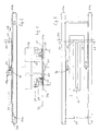
- the embodiment of the device shown in FIGS. 1 to 3 has two parallel conveyor belts 23a, which are for an endless Orbiting around two spaced conveyor belt shafts 20a and 20b are arranged. There is a between the conveyor belts 23a Inlet plate 25 and a 28 in the sheet transport direction (Arrow) extending opening 24 for the passage of the shown folding sword provided.
- the inlet plate 25 forms the working area of the folding sword.
- the end of the work area is limited by stops 29 by a cross member 54 are held and in the transport level 33 of a sheet 21 to be folded.
- the stops 29 are the end opposite the inlet side for the sheet 21 assigned to the opening 24.
- the embodiment of the device as shown in FIGS. 4 to 6 has a sensor 34 which is in the sheet transport direction 28 (arrow) at a distance of a few centimeters is arranged in front of the stops 29.
- Sensor 34 is ordinary a photocell that the leading edge of the tapered Sheet 21 detected and emits a corresponding signal.
- This Signal serves to activate a device 30 for slowing down of the bow 21 in front of the stops 29, which is in the design 4 to 6 by two lifting devices 39 for the bow 21 is reached, each of which has a long side is assigned to the opening 24 for the folding sword.
- the sheet 21 runs on two Inlet plate 25 associated inner conveyor belts 23a and on outer conveyor belts 20b, between which conductor devices 35 are arranged in the form of U-profiles.
- To Both sides of the opening 24 for the folding sword are in the Inlet plate 25 slots underneath the strips 32 recessed.
- Each lifting device 39 has a magnet 39c with an in its longitudinally reciprocable core rod on which an intermediate rod is articulated, which is fixed to a crossbar 39b is connected, which is transverse to the transport plane 33 of the Arch 21 extends and through openings in the vertical Flanges of the inlet plate 25 passes.
- a crossbar 39b On the crossbar 39b are levers 39a attached to a longitudinal displacement of the core rod of the magnet 39c and change their vertical position so that the Guide devices 35 and the strips 32 over the transport plane 33 of the arch 21, as shown in FIG. 5 is shown.
- the hold-down rollers 27a are thereby a magnet 27b also controlled by the sensor 34, however, the hold down engagement with the arch 21 preserved.
- the clutch 42 consists of a clutch roller 42a on the one leg of an angle lever articulated on the machine side 42c attacks, the other end with the core rod one Magnet 42e is hinged, the clutch roller 42a biased into its coupling position by a spring 42b is.
- the sensor 34 in the form of a photocell the leading edge of the incoming sheet 21 detected, it gives a signal to the Magnet 42e, which thereby runs its core rod in its longitudinal direction adjusted so that the frictional engagement of a clutch belt 24d that around the conveyor belt shaft 40e and Conveyor belt shaft 20a runs, is relaxed, causing the Conveyor belts 23a and 23b which run around in their longitudinal direction conveyor belt shaft 20a divided in the middle run to a standstill come.
- the bow 21 before the attacks 29 braked so that an impact on the stops 29 is prevented will while the working area of the folding sword 22 upstream feeder continues and then the next sheet can transport. With this configuration can the sheet 21 even at high folding speed gently brought up to the stops 29 and safely aligned become.
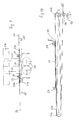
- FIGS. 9 and 10 has a work area the feed device, not shown, associated with the folding blade with two conveyor belt shafts 20a and 20b, around which two conveyor belts 23a circulate endlessly, and also outer conveyor belts, not shown, can be provided.
- the inlet plate 25 are assigned Strips 33 and, to the side thereof, guide devices 35 intended.
- Below the opening 24 in Fig. 9 is the pair of folding rollers 26, in the gap of which is not shown Folding sword folded by him through the opening 24 in the Inlet plate 25 introduces so that the arc between the rollers are folded and transported downwards.
- the working area of the folding sword in the direction of sheet travel 28 downstream conveyor belt shaft 20b is via a belt tensioning lever 5 connected to a belt tension shaft 4 so that based on a signal from the sensor 34 for the sheet feed the eccentrically formed band tension shaft 34 from one Motor is rotated by 180 °, whereby the ligament tensioning lever 38 with the conveyor belts 23a under the transport plane 33 be lowered.
- the sheet 21 thereby bumps gently against the Stops 29 and lies on the U-shaped guide devices 35 and on the strip 32 on the inlet plate 25.
- the ligament tensioning shaft 37 is turned through 180 ° rotated further so that the conveyor belts 23a again in the Transport level 33 lie.
- FIGS. 9 and 10 can be used for further braking Brush 31 against the strip 32, as in the Embodiment of FIGS. 1 to 3 and hold-down 24 in the form provided by retention brushes.
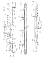
- the conveyor belt shaft 20a lies on the Feeder for the sheet far in front of the work area of the folding sword 22.
- the transbands 23a are in front of the work area the folding sword 22 deflected with the aid of rollers, in pairs, one on each side of the inlet plate 25 are provided so that the tape guide only is described using the one set of roles.
- the conveyor belt 23a After deflecting the conveyor belt 23a around the conveyor belt shaft 20b, the conveyor belt 23a becomes a fifth roller 47 deflected from the level of the lower run to the upper run and by a distance in the sheet transport direction 28 sixth roller 48 guided so that it is parallel to the upper run of the conveyor belt 23a below it opposite to the belt running direction 28 of the upper run to a seventh roll 49 is guided, which is arranged at a distance from the third roller 45 and the conveyor belt 23a to an eighth roller 50 deflects the conveyor belt 23a back into the plane of lower runs.
- the third roll 45 and the seventh roll 49 are by one Actuator 51 in the form of a rod rigidly together connected.
- the actuator 51 is at its free end in front of the conveyor belt shaft 20b with a linkage mechanism 51a connected to the one by a magnet 51b back and forth movable core hears.
- the sensor 34 When the sheet 21 reaches the sensor 34 with its front edge, the sensor 34 gives a signal to the magnet 51b which thereby actuating the linkage 50a so that the actuator 51 the third roller 45 and the rigidly connected seventh Roll 49 pulls in the sheet running direction 28.
- the third moves Roll 45 tape length without it to the working area of the Section 53 of the conveyor belts assigned to the folding sword 22 To pass on 23a.
- the seventh roller 49 gives the same ratio tape length previously drawn back again, see above that the section 52 of the conveyor belts 23a in front of the work area of the folding blade 52 at the same speed can continue to run.
- the section 53 of the conveyor belts 23a in The working area of the folding sword 22 comes to a brief standstill.
- Hold-down rollers 27a press via a sensor-controlled one Magnets 27b at the beginning of the work area of the folding sword 22 on the conveyor belts 23a, whereby the sheet 21st is also slowed down. In this way, the sheet 21 gently against the stops 29 even at high folding speed introduced and aligned safely.
Landscapes
- Engineering & Computer Science (AREA)
- Mechanical Engineering (AREA)
- Folding Of Thin Sheet-Like Materials, Special Discharging Devices, And Others (AREA)
Abstract
Description
- Fig. 1
- einen Querschnitt durch eine erste Ausführungsform der Vorrichtung,
- Fig. 2
- die Vorrichtung von Fig. 1 im Längsschnitt,
- Fig. 3
- die Vorrichtung von Fig. 1 in der Draufsicht,
- Fig. 4
- eine zweite Ausführungsform der Vorrichtung im Querschnitt,
- Fig. 5
- die Ausführungsform von Fig. 4 im Längsschnitt,
- Fig. 6
- in einer Ansicht wie Fig. 5 eine Einzelheit der Vorrichtung,
- Fig. 7
- eine dritte Ausführungsform der Vorrichtung im Längsschnitt,
- Fig. 8
- die Vorrichtung von Fig. 7 in der Draufsicht,
- Fig. 9
- eine vierte Ausführungsform der Vorrichtung im Querschnitt,
- Fig. 10
- die Vorrichtung von Fig. 9 im Längsschnitt,
- Fig. 11
- eine fünfte Ausführungsform der Vorrichtung im Querschnitt,
- Fig. 12
- die Vorrichtung von Fig. 11 im Längsschnitt und
- Fig. 13
- die Vorrichtung von Fig. 12 in der Draufsicht.
Claims (13)
- Vorrichtung zum Falzen eines Bogens (21) mittels eines Falzschwerts (22)gekennzeichnetmit einer Transportbänder (23a, 23b) und Transportrollen (20a, 20b) aufweisenden Zuführeinrichtung zum Transportieren des Bogens (21) in den Arbeitsbereich des Falzschwerts (22), der von einem sich zwischen den Transportbändern (23a) befindlichen, eine Öffnung (24) für das Falzschwert (22) aufweisenden Einlaufblech (25) gebildet wird, unter der der Spalt eines Transport- und Falzwalzenpaares (26) angeordnet istmit oberhalb der Zuführeinrichtung angeordneten Einrichtungen (27) zum Niederhalten des Bogens (21) undmit wenigstens einem quer zur Bogentransportrichtung (28) angeordneten Anschlag (29) zum Positionieren des Bogens (21) im Arbeitsbereich des Falzschwertes (22)durch wenigstens eine dem Anschlag (29) in Bogentransportrichtung (28) vorgeordnete Einrichtung (30) zum Verlangsamen der Transportgeschwindigkeit des Bogens (21).
- Vorrichtung nach Anspruch 1, dadurch gekennzeichnet, daß die Einrichtung (30) zum Verlangsamen der Transportgeschwindigkeit des Bogens (21) Bürsten (31) aufweist, die mit der Bogenoberfläche in Reibungseingriff bringbar sind.
- Vorrichtung nach Anspruch 2, dadurch gekennzeichnet, daß die Bürsten (31) in ihre Reibungseingriffsstellung mit dem Bogen (21) vorgespannt sind.
- Vorrichtung nach Anspruch 2 oder 3, dadurch gekennzeichnet, daß die Bürsten (31) an den Einrichtungen (27) zum Niederhalten des Bogens (21) angeordnet sind.
- Vorrichtung nach einem der Ansprüche 2 bis 4,' dadurch gekennzeichnet, daß auf das Einlaufblech (25) sich in Bogentransportrichtung (28) unterhalb der Bürsten (31) erstreckende Streifen (32) aufgelegt sind, deren Dicke so bemessen ist, daß ihre dem Bogen (21) zugewandte Seite in der Transportebene (33) der Transportbänder (23a, 23b) liegt.
- Vorrichtung nach Anspruch 1, gekennzeichnet durch wenigstens einen dem Anschlag (29) in Bogentransportrichtung (28) vorgeordneten Sensor (34) zum Erfassen der Zuführung eines Bogens (21) und zum Aktivieren der Einrichtung (30) zum Verlangsamen der Transportgeschwindigkeit des Bogens (21).
- Vorrichtung nach Anspruch 6, dadurch gekennzeichnet, daß die Einrichtung (30) zum Verlangsamen der Transportgeschwindigkeit des Bogens (21) wenigstens eine über die Transportebenen (33) der Transportbänder (23a, 23b) anhebbare Leiteinrichtung (35) für den Bogen (21) aufweist und daß die Einrichtungen (27) zum Niederhalten des Bogens (21) zur Aufrechterhaltung ihres Eingriffs mit dem Bogen (21) gemeinsam mit der Leiteinrichtung (35) anhebbar sind.
- Vorrichtung nach Anspruch 6, dadurch gekennzeichnet, daß die Einrichtung (30) zum Verlangsamen der Transportgeschwindigkeit des Bogens (21) eine Einrichtung (36) zum Absenken der Transportbänder (23a, 23b) unter die Ebene des Einlaufblechs (25) aufweist.
- Vorrichtung nach Anspruch 8, dadurch gekennzeichnet, daß die Einrichtung (26) zum Absenken der Transportbänder (23a, 23b) eine exzentrische Bänderspannwelle (37) aufweist, die mit der dem Anschlag (29) in Bogentransportrichtung (28) nachgeordneten Transportbandwelle (20b) über Bänderspannhebel (38) verbunden und zwischen einer der Bogentransportstellung der Transportbänder (23a, 23b) entsprechenden Position und einer der abgesenkten Stellung der Transportbänder (27a, 23b) entsprechenden Position verstellbar ist.
- Vorrichtung nach Anspruch 8 oder 9 in Verbindung mit Bürstenanordnungen nach einem der Ansprüche 2 bis 5.
- Vorrichtung nach Anspruch 6, dadurch gekennzeichnet, daß in Bogentransportrichtung (28) von der Zuführeinrichtung zum Transportieren des Bogens (21) in den Arbeitsbereich des Falzschwertes (22) eine weitere Transportbandwellen (40a, 40b) und Transportbänder (41a, 41b) aufweisende Bogenzuführeinrichtung angeordnet ist, und daß den treibenden Transportbandwellen (40b, 20a) der beiden Bogenzuführeinrichtungen eine Kupplung (42) zugeordnet ist, die eingekuppelt die beiden Bogenzuführeinrichtungen für einen Synchronlauf verbindet und ausgekuppelt den Antrieb der Transportbandwelle (20a) der Zuführeinrichtung zum Transportieren des Bogens (21) in den Arbeitsbereich des Falzschwerts (22) unterbricht.
- Vorrichtung nach Anspruch 6, dadurch gekennzeichnetdaß sich die Zuführeinrichtungen zum Transportieren des Bogens (21) in Bogentransportrichtung (28) vor den Arbeitsbereich des Falzschwerts (22) erstreckt,daß die Transportbänder (23a) vor dem Arbeitsbereich des Falzschwerts (22) jeweils seitlich vom Einlaufblech (25) durch eine erste Rolle (43) aus ihrer Bogentransportebene zu ihrem unteren Trum hin und durch eine zweite Rolle (44) parallel zum unteren Trum und oberhalb davon geführt und über eine dritte Rolle (45) und eine vierte Rolle (46) wieder in die Ebene des oberen Trums zurückgeführt werden,daß die Transportbänder (23a), nachdem sie um die dem Arbeitsbereich des Falzschwerts (22) nachgeordnete Transportbandwelle (20b) geführt sind durch eine fünfte Rolle (47) aus der Ebene ihres unteren Trums zu ihrem oberen Trum hin und durch eine sechste Rolle (48) parallel zum oberen Trum und unterhalb davon geführt und über eine siebente Rolle (49) und eine achte Rolle (50) wieder in die Ebene des unteren Trums zurückgeführt werden,daß die dritte Rolle (45) und die siebte Rolle (49) mit einem gemeinsamen Betätigungsglied (51) für eine Bewegung im wesentlichen parallel zur Bogentransportrichtung (28) verbunden sind unddaß das Betätigungsglied (51) vom Sensor (34) so gesteuert wird,daß bei Erfassen einer Bogenzuführung die verbundenen Rollen (45, 49) in Bogentransportrichtung (28) bewegt werden, wodurch durch die dritte Rolle (45) Bandlänge eingezogen wird, ohne sie an den Abschnitt (53) der Transportbänder (23a) im Arbeitsbereich des Falzschwerts (22) weiterzugeben,während die siebte Rolle (49) im gleichen Verhältnis bereits früher eingezogene Bandlänge wieder zurückgibt, so daß der Abschnitt (52) der Transportbänder (23a) vor dem Arbeitsbereich des Falzschwerts (22) mit der Transportgeschwindigkeit des Bogens (21) weiterläuft,während der dem Arbeitsbereich des Falzschwerts (22) zugeordneten Abschnitt (53) der Transportbänder (23a) kurz zum Stehen kommen und der Bogen (21) abbremsen,wonach die verbundenen Rollen (45, 49) in ihre Ausgangsstellung unter Beschleunigung des dem Arbeitsbereich des Falzschwerts (22) zugeordneten Abschnitts (53) der Transportbänder (23a) zurückbewegt werden.
- Vorrichtung mit zwei inneren Transportbändern (23a), die nach Anspruch 11 geführt sind, und mit wenigstens zwei äußeren Transportbändern, denen eine Leiteinrichtung nach Anspruch 7 zugeordnet ist.
Priority Applications (2)
| Application Number | Priority Date | Filing Date | Title |
|---|---|---|---|
| EP20000116400 EP1176109B1 (de) | 2000-07-28 | 2000-07-28 | Vorrichtung zum Falzen eines Bogens mittels eines Falzschwerts |
| DE50003905T DE50003905D1 (de) | 2000-07-28 | 2000-07-28 | Vorrichtung zum Falzen eines Bogens mittels eines Falzschwerts |
Applications Claiming Priority (1)
| Application Number | Priority Date | Filing Date | Title |
|---|---|---|---|
| EP20000116400 EP1176109B1 (de) | 2000-07-28 | 2000-07-28 | Vorrichtung zum Falzen eines Bogens mittels eines Falzschwerts |
Publications (2)
| Publication Number | Publication Date |
|---|---|
| EP1176109A1 true EP1176109A1 (de) | 2002-01-30 |
| EP1176109B1 EP1176109B1 (de) | 2003-10-01 |
Family
ID=8169385
Family Applications (1)
| Application Number | Title | Priority Date | Filing Date |
|---|---|---|---|
| EP20000116400 Expired - Lifetime EP1176109B1 (de) | 2000-07-28 | 2000-07-28 | Vorrichtung zum Falzen eines Bogens mittels eines Falzschwerts |
Country Status (2)
| Country | Link |
|---|---|
| EP (1) | EP1176109B1 (de) |
| DE (1) | DE50003905D1 (de) |
Cited By (2)
| Publication number | Priority date | Publication date | Assignee | Title |
|---|---|---|---|---|
| DE20307172U1 (de) | 2003-05-08 | 2003-07-10 | Maschinenbau Oppenweiler Binder GmbH & Co. KG, 71570 Oppenweiler | Schwertfalzwerk |
| EP1900660A3 (de) * | 2006-09-13 | 2008-12-17 | Heidelberger Druckmaschinen AG | Vorrichtung zum Positionieren einer Hinterkante von Bogen |
Citations (3)
| Publication number | Priority date | Publication date | Assignee | Title |
|---|---|---|---|---|
| US4573671A (en) * | 1984-05-07 | 1986-03-04 | Harris-Marinoni S.A. | Automatic setting device for slowing down a signature prior to folding in printing press chopper folders |
| US4746108A (en) * | 1985-12-04 | 1988-05-24 | Komori Printing Machinery Co., Ltd. | Chopper device for use in a folder |
| US5405127A (en) * | 1993-04-14 | 1995-04-11 | Didde Web Press Corporation | Signature folder apparatus for web fed printing press with sheet stop adjustment |
-
2000
- 2000-07-28 EP EP20000116400 patent/EP1176109B1/de not_active Expired - Lifetime
- 2000-07-28 DE DE50003905T patent/DE50003905D1/de not_active Expired - Lifetime
Patent Citations (3)
| Publication number | Priority date | Publication date | Assignee | Title |
|---|---|---|---|---|
| US4573671A (en) * | 1984-05-07 | 1986-03-04 | Harris-Marinoni S.A. | Automatic setting device for slowing down a signature prior to folding in printing press chopper folders |
| US4746108A (en) * | 1985-12-04 | 1988-05-24 | Komori Printing Machinery Co., Ltd. | Chopper device for use in a folder |
| US5405127A (en) * | 1993-04-14 | 1995-04-11 | Didde Web Press Corporation | Signature folder apparatus for web fed printing press with sheet stop adjustment |
Cited By (4)
| Publication number | Priority date | Publication date | Assignee | Title |
|---|---|---|---|---|
| DE20307172U1 (de) | 2003-05-08 | 2003-07-10 | Maschinenbau Oppenweiler Binder GmbH & Co. KG, 71570 Oppenweiler | Schwertfalzwerk |
| EP1475338A1 (de) * | 2003-05-08 | 2004-11-10 | MASCHINENBAU OPPENWEILER BINDER GmbH & Co. KG | Schwertfalzwerk |
| CN100336708C (zh) * | 2003-05-08 | 2007-09-12 | 奥彭魏勒宾德尔机械制造公司 | 刀式折页装置 |
| EP1900660A3 (de) * | 2006-09-13 | 2008-12-17 | Heidelberger Druckmaschinen AG | Vorrichtung zum Positionieren einer Hinterkante von Bogen |
Also Published As
| Publication number | Publication date |
|---|---|
| DE50003905D1 (de) | 2003-11-06 |
| EP1176109B1 (de) | 2003-10-01 |
Similar Documents
| Publication | Publication Date | Title |
|---|---|---|
| DE2518373C2 (de) | Einrichtung zum Vergleichmässigen der gegenseitigen Abstände von in einem Schuppenstrom aufeinanderfolgenden Druckprodukten | |
| EP0073388B1 (de) | Vorrichtung zum Ändern der Bewegungsrichtung von Briefen und ähnlichen rechteckigen Sendungen | |
| DE3700959C2 (de) | Bogensammelvorrichtung | |
| DE19955815A1 (de) | Blattrenner zum Zusammenstellen von Druckbögen und zugehöriges Verfahren | |
| DE4225607A1 (de) | Umsteuerbare kollationiermaschine | |
| DE9108466U1 (de) | Vorrichtung zum Drahtheften von mehrteiligen Druckereierzeugnissen | |
| EP0055405B1 (de) | Bänderstrecke zum Transport und zur Verlangsamung von Falzprodukten | |
| CH634278A5 (de) | Falzapparat. | |
| DE2539799B2 (de) | Lichtpausmaschine mit einer Repetiervorrichtung | |
| DE3212350C2 (de) | Vorrichtung zum Auseinanderziehen von ineinandersteckenden Bogen | |
| EP1196345B1 (de) | Verfahren und vorrichtung zum geschuppten anordnen von zumindest zwei blättern | |
| EP0205116B1 (de) | Falzapparat | |
| EP1176109B1 (de) | Vorrichtung zum Falzen eines Bogens mittels eines Falzschwerts | |
| EP1494946B1 (de) | Vorrichtung zum ausrichten von bogen und ein verfahren zum ausrichten von bogen quer zur bogenlaufrichtung | |
| DE19627490A1 (de) | Fördereinrichtung für Druckereierzeugnisse | |
| EP2316767B1 (de) | Verfahren und Vorrichtung zum Herstellen von Stapeln aus Druckprodukten | |
| EP1944257B1 (de) | Vorrichtung zum seitlichen Ausrichten von Druckereiprodukten | |
| DE102008007965B4 (de) | Falztaschenvorrichtung | |
| DE4012517A1 (de) | Falt- und vorschubeinrichtung | |
| DE3919436C2 (de) | ||
| DE9103137U1 (de) | Vorrichtung zur Bildung einer Folge von sich unterschuppenden Gegenständen | |
| DE10059587A1 (de) | Verfahren und Vorrichtung zum Falzen von Materialbogen | |
| DE4447541C2 (de) | Vorrichtung zum seitlichen Ausrichten von Bogen | |
| DE615323C (de) | Vorrichtung zum selbsttaetigen Zufuehren von Bogen zu Falzmaschinen | |
| DE4035106A1 (de) | Falzmaschine |
Legal Events
| Date | Code | Title | Description |
|---|---|---|---|
| PUAI | Public reference made under article 153(3) epc to a published international application that has entered the european phase |
Free format text: ORIGINAL CODE: 0009012 |
|
| AK | Designated contracting states |
Kind code of ref document: A1 Designated state(s): AT BE CH CY DE DK ES FI FR GB GR IE IT LI LU MC NL PT SE Kind code of ref document: A1 Designated state(s): DE FR GB IT |
|
| AX | Request for extension of the european patent |
Free format text: AL;LT;LV;MK;RO;SI |
|
| 17P | Request for examination filed |
Effective date: 20020315 |
|
| AKX | Designation fees paid |
Free format text: DE FR GB IT |
|
| GRAH | Despatch of communication of intention to grant a patent |
Free format text: ORIGINAL CODE: EPIDOS IGRA |
|
| GRAS | Grant fee paid |
Free format text: ORIGINAL CODE: EPIDOSNIGR3 |
|
| GRAA | (expected) grant |
Free format text: ORIGINAL CODE: 0009210 |
|
| RAP1 | Party data changed (applicant data changed or rights of an application transferred) |
Owner name: MASCHINENBAU OPPENWEILERBINDER GMBH & CO. |
|
| AK | Designated contracting states |
Kind code of ref document: B1 Designated state(s): DE FR GB IT |
|
| REG | Reference to a national code |
Ref country code: GB Ref legal event code: FG4D Free format text: NOT ENGLISH |
|
| REG | Reference to a national code |
Ref country code: IE Ref legal event code: FG4D Free format text: GERMAN |
|
| REF | Corresponds to: |
Ref document number: 50003905 Country of ref document: DE Date of ref document: 20031106 Kind code of ref document: P |
|
| RAP2 | Party data changed (patent owner data changed or rights of a patent transferred) |
Owner name: MASCHINENBAU OPPENWEILERBINDER GMBH & CO. KG |
|
| GBT | Gb: translation of ep patent filed (gb section 77(6)(a)/1977) |
Effective date: 20040216 |
|
| ET | Fr: translation filed | ||
| REG | Reference to a national code |
Ref country code: IE Ref legal event code: FD4D |
|
| PLBE | No opposition filed within time limit |
Free format text: ORIGINAL CODE: 0009261 |
|
| STAA | Information on the status of an ep patent application or granted ep patent |
Free format text: STATUS: NO OPPOSITION FILED WITHIN TIME LIMIT |
|
| 26N | No opposition filed |
Effective date: 20040702 |
|
| PGFP | Annual fee paid to national office [announced via postgrant information from national office to epo] |
Ref country code: FR Payment date: 20090722 Year of fee payment: 10 |
|
| PGFP | Annual fee paid to national office [announced via postgrant information from national office to epo] |
Ref country code: GB Payment date: 20090722 Year of fee payment: 10 |
|
| PGFP | Annual fee paid to national office [announced via postgrant information from national office to epo] |
Ref country code: IT Payment date: 20100723 Year of fee payment: 11 Ref country code: DE Payment date: 20100804 Year of fee payment: 11 |
|
| GBPC | Gb: european patent ceased through non-payment of renewal fee |
Effective date: 20100728 |
|
| REG | Reference to a national code |
Ref country code: FR Ref legal event code: ST Effective date: 20110331 |
|
| PG25 | Lapsed in a contracting state [announced via postgrant information from national office to epo] |
Ref country code: FR Free format text: LAPSE BECAUSE OF NON-PAYMENT OF DUE FEES Effective date: 20100802 |
|
| PG25 | Lapsed in a contracting state [announced via postgrant information from national office to epo] |
Ref country code: GB Free format text: LAPSE BECAUSE OF NON-PAYMENT OF DUE FEES Effective date: 20100728 |
|
| PG25 | Lapsed in a contracting state [announced via postgrant information from national office to epo] |
Ref country code: DE Free format text: LAPSE BECAUSE OF NON-PAYMENT OF DUE FEES Effective date: 20120201 |
|
| REG | Reference to a national code |
Ref country code: DE Ref legal event code: R119 Ref document number: 50003905 Country of ref document: DE Effective date: 20120201 |
|
| PG25 | Lapsed in a contracting state [announced via postgrant information from national office to epo] |
Ref country code: IT Free format text: LAPSE BECAUSE OF NON-PAYMENT OF DUE FEES Effective date: 20110728 |