EP1176253A1 - Seilsystem - Google Patents
Seilsystem Download PDFInfo
- Publication number
- EP1176253A1 EP1176253A1 EP01114305A EP01114305A EP1176253A1 EP 1176253 A1 EP1176253 A1 EP 1176253A1 EP 01114305 A EP01114305 A EP 01114305A EP 01114305 A EP01114305 A EP 01114305A EP 1176253 A1 EP1176253 A1 EP 1176253A1
- Authority
- EP
- European Patent Office
- Prior art keywords
- rope
- cylinder
- pressure
- signal
- measuring device
- Prior art date
- Legal status (The legal status is an assumption and is not a legal conclusion. Google has not performed a legal analysis and makes no representation as to the accuracy of the status listed.)
- Granted
Links
- 239000011111 cardboard Substances 0.000 description 4
- 239000011087 paperboard Substances 0.000 description 4
- 238000001035 drying Methods 0.000 description 2
- 238000004519 manufacturing process Methods 0.000 description 2
- 239000000123 paper Substances 0.000 description 2
- 238000003490 calendering Methods 0.000 description 1
- 239000011248 coating agent Substances 0.000 description 1
- 238000000576 coating method Methods 0.000 description 1
- 238000010276 construction Methods 0.000 description 1
- 238000005516 engineering process Methods 0.000 description 1
- 238000000926 separation method Methods 0.000 description 1
Images

Classifications
-
- D—TEXTILES; PAPER
- D21—PAPER-MAKING; PRODUCTION OF CELLULOSE
- D21G—CALENDERS; ACCESSORIES FOR PAPER-MAKING MACHINES
- D21G9/00—Other accessories for paper-making machines
- D21G9/0063—Devices for threading a web tail through a paper-making machine
- D21G9/0072—Devices for threading a web tail through a paper-making machine using at least one rope
Definitions
- the present invention relates to a rope system with at least one endless rope, which is arranged so that it rotates through a machine, being in its longitudinal direction is excited.
- a desired voltage value is generated during the operation of the machine maintained, for example by means of a rope tensioning device.
- a rope system is often used to make the Threading paper or cardboard web into the machine (especially into the dryer section), when the machine is started or after a web break.
- two (sometimes three) endless ropes used together along the path of the Run web, for example through the drying or calendering or coating section.
- the two ropes form a rope cutter.
- the ropes take the start of an edge strip (e.g. a so-called "ribbon") Paper or cardboard web and lead the edge strip through the section.
- An object of the invention is to provide an improved cable system which the risk of the described damage is avoided or at least reduced.
- the rope system comprises a measuring device for measuring the tension value in the at least one endless rope.
- the voltage value during the Operation of the machine measured continuously.
- Said measuring device is designed such that it is excessive in the rope Tension value detected that is higher than the desired, normally present in the rope Voltage value. Such an excessive voltage value can result if the rope is blocked or if any other fault occurs in the rope system.
- a rope severing device for severing the endless rope, if the rope is suddenly stretched excessively, the rope cutting device becomes active immediately when the excessive voltage level is detected.
- the machine e.g. papermaking machine
- the machine can be cut after of the rope continue to work in the normal way because of any risk of damage the machine has been eliminated.
- cutting through the Rope some loss. However, this loss is much less than the damage that (in In the event of an accident) the mechanical devices would be added if the rope would not cut.
- the cable system according to the invention preferably has a cable tensioning device a cylinder which is suitable around at least one sheave wrapped in the rope shift to tension the rope.
- a selected cylinder is selected Pressure supplied, which corresponds to the desired voltage value.
- the above Measuring device designed such that it the pressure prevailing in the cylinder measures.
- the measuring device is designed as a pressure switch that transmits a signal generated when the pressure in the cylinder exceeds the selected pressure. This The signal is then transmitted to the rope cutting device.
- the cable separating device preferably comprises a cylinder which holds the cable separating device activated.
- a control valve can be provided which - depending on the said signal - controls the cylinder so that it activates the rope cutting device, if the said signal exists.
- the control valve is controlled by a pressure medium (e.g. compressed air) that the control valve is supplied if the said signal exists.
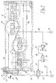
- the rope tensioning device 8 of the rope system comprises two movable Pulleys 11 and 12 that support a rope labeled 9a, 9, 9b.
- 9a is the incoming run
- 9b the outgoing run of the rope 9.
- the arrangement is such that the rope, where it wraps around the two pulleys 11, 12, a single S forms (or an inverted S).
- the two pulleys 11, 12 are in opposite Directions (each e.g. by a distance L) can be shifted from one original position (shown in full lines) in an end position, in dash-dotted lines Lines is shown. After that, the rope was extended a length, which is four times the distance L.
- the rope tensioning device 8 (as shown in FIGS. 1 and 2) comprises a stationary one Frame 10 which carries two rodless pneumatic cylinders 14 and 15. Every cylinder 14, 15 has a movable piston (not shown) which is connected to a pulley carrier 13 is connected. Each pulley carrier 13 serves to support a rotatable Pulley 11, 12 (e.g. by means of a roller bearing).
- the tensioning device is arranged, for example, in a paper manufacturing machine, where the rope is needed.
- the clamping device (according to FIG. 1) arranged horizontally or vertically or upside down or in any other position.
- two or more tensioners can be combined to to tension a two-rope system or a three-rope system.
- each rope forms an endless loop that rotates at the working speed of the machine.
- the rope cutting device 20 comprises a pivotable knife 21 which is suitable for use with a stationary counter knife 22 to work together.
- the knife 21 can be pivoted about a bolt, which has an axis 23.
- the knife 21 on the piston 24 is a double-acting pneumatic cylinder 25 coupled, which in turn coupled to the frame 10 is.
- the valve 30 is switched, for example pneumatically, by supplying pressure to the valve 30 from the pressure source 31 via a Line 33, via an auxiliary control valve 34 and via a line 35.
- the said signal can be sent directly from the measuring device 36 to the control valve via a line 38 30 are supplied to switch this).
- Said measuring device 36 is suitable for increasing the tension value in the rope 9 measure up. Normally, the tension in the rope 9 is at a desired tension value held, e.g. by maintaining a selected pressure from one Pressure source 19 is fed to the cylinder 15 via a line 18.
- the measuring device 36 Only when the tension in the rope 9 rises to an excessive tension value (which is above the desired value mentioned), from which in the cylinder 15 and In line 18, an increased pressure results, the measuring device 36 generates the above Signal which is transmitted through line 37.
- the measuring device 36 as a pressure switching valve (sometimes called “cut-in valve") that line 18 connects to line 37 when the pressure in line 18 exceeds a certain value; this can be adjusted, for example by adjusting the force of a spring 39.
Landscapes
- Paper (AREA)
- Ropes Or Cables (AREA)
- Laying Of Electric Cables Or Lines Outside (AREA)
- Force Measurement Appropriate To Specific Purposes (AREA)
Abstract
Description
Claims (11)
- Seilsystem mit den folgenden Merkmalen:a) vorgesehen ist ein endloses Seil (9), das durch eine Maschine umläuft, wobei es in seiner Längsrichtung gespannt wird und wobei ein gewünschter Spannungswert aufrechterhalten wird;b) eine Meßeinrichtung (36) ist vorgesehen zum Messen des Spannungswertes in dem genannten endlosen Seil (9);c) vorgesehen ist eine Seiltrenneinrichtung (20) zum Durchtrennen des endlosen Seiles (9), wenn die Meßeinrichtung (36) in dem Seil einen übermäßigen Spannungswert feststellt, der größer ist als der genannte gewünschte Spannungswert.
- Seilsystem nach Anspruch 1, das zusätzlich eine Seilspanneinrichtung (8) aufweist.
- Seilsystem nach Anspruch 2, mit den folgenden Merkmalen:a) die Seilspanneinrichtung (8) umfaßt einen Zylinder (15), der geeignet ist zum Verlagern einer vom genannten Seil (9) umschlungenen Seilscheibe (12) zwecks Spannen des Seiles;b) dem genannten Zylinder (15) wird ein ausgewählter Druck zugeführt, der dem gewünschten Spannungswert entspricht.
- Seilsystem nach Anspruch 3, worin die genannte Meßeinrichtung (36) geeignet ist zum Messen des in dem genannten Zylinder (15) herrschenden Druckes.
- Seilsystem nach Anspruch 4, worin die Meßeinrichtung (36) als ein Druckschalter ausgebildet ist, der ein Signal erzeugt, wenn der im Zylinder (15) herrschende Druck den ausgewählten Druck übersteigt.
- Seilsystem nach Anspruch 5, worin der Druckschalter (36) derart ausgebildet ist, daß das genannte Signal (z.B. über Leitung 37) der genannten Seiltrenneinrichtung (20) zugeführt wird.
- Seilsystem nach Anspruch 1, worin die genannte Seiltrenneinrichtung (20) einen Zylinder (24, 25) aufweist zum Aktivieren der Seiltrenneinrichtung.
- Seilsystem nach Anspruch 7, worin ein Steuerventil (30) vorgesehen ist, das - in Abhängigkeit von dem genannten Signal - den genannten Zylinder (24, 25) steuert, so daß der Zylinder die Seiltrenneinrichtung (20) aktiviert, wenn das genannte Signal vorhanden ist.
- Seilsystem nach Anspruch 8, worin das genannte Steuerventil (30) durch ein Druckmittel (z.B. Druckluft) gesteuert wird, wobei das Druckmittel dem Steuerventil zugeführt wird, wenn das genannte Signal vorhanden ist.
- Seilsystem nach Anspruch 2, worin die genannte Seiltrenneinrichtung (20) an der Seilspanneinrichtung (8) angeordnet ist.
- Seilsystem nach Anspruch 10, worin die Seiltrenneinrichtung (20) an das Einlaufende der Seilspanneinrichtung (8) befestigt ist.
Applications Claiming Priority (2)
| Application Number | Priority Date | Filing Date | Title |
|---|---|---|---|
| DE20012301U DE20012301U1 (de) | 2000-07-12 | 2000-07-12 | Seilsystem |
| DE20012301U | 2000-07-12 |
Publications (2)
| Publication Number | Publication Date |
|---|---|
| EP1176253A1 true EP1176253A1 (de) | 2002-01-30 |
| EP1176253B1 EP1176253B1 (de) | 2005-04-27 |
Family
ID=7943995
Family Applications (1)
| Application Number | Title | Priority Date | Filing Date |
|---|---|---|---|
| EP01114305A Expired - Lifetime EP1176253B1 (de) | 2000-07-12 | 2001-06-13 | Seilsystem |
Country Status (5)
| Country | Link |
|---|---|
| US (1) | US6499641B2 (de) |
| EP (1) | EP1176253B1 (de) |
| AT (1) | ATE294280T1 (de) |
| CA (1) | CA2352847A1 (de) |
| DE (2) | DE20012301U1 (de) |
Families Citing this family (4)
| Publication number | Priority date | Publication date | Assignee | Title |
|---|---|---|---|---|
| DE20012301U1 (de) * | 2000-07-12 | 2000-09-21 | Voith Sulzer Papiertechnik Patent GmbH, 89522 Heidenheim | Seilsystem |
| DE102009053342A1 (de) * | 2009-11-17 | 2011-05-26 | Eder Maschinenbau Gmbh | Einrichtung zum Unterbrechen einer Zugkraft in einem Zugsystem |
| CN104210511A (zh) * | 2013-06-02 | 2014-12-17 | 淮北金源工贸有限责任公司 | 一种无极绳绞车气动道岔 |
| CN115285767B (zh) * | 2022-10-08 | 2023-02-03 | 常州精测新能源技术有限公司 | 一种高精度气浮装置及尾卷张力控制方法、电池生产设备 |
Citations (3)
| Publication number | Priority date | Publication date | Assignee | Title |
|---|---|---|---|---|
| US5377892A (en) * | 1993-08-12 | 1995-01-03 | Wespatt, Inc. | Fluid pressure tensioning apparatus for a web threading endless rope |
| DE29808786U1 (de) * | 1997-05-21 | 1998-08-20 | Valmet Corp., Helsinki | Vorrichtungsanordnung zur Kontrolle der Spannung der Seilbahn einer Papier-/Kartonmaschine und zur Überwachung des Zustands von Seil und Seilscheibe |
| DE20012301U1 (de) * | 2000-07-12 | 2000-09-21 | Voith Sulzer Papiertechnik Patent GmbH, 89522 Heidenheim | Seilsystem |
Family Cites Families (9)
| Publication number | Priority date | Publication date | Assignee | Title |
|---|---|---|---|---|
| US3882748A (en) * | 1974-03-25 | 1975-05-13 | Us Navy | Cable cutter assembly |
| US3962943A (en) * | 1974-08-14 | 1976-06-15 | Allen Burl A | Safety apparatus for a cable feed system |
| US4480801A (en) * | 1982-05-13 | 1984-11-06 | Motter Printing Press Co. | Webbing system |
| US5263623A (en) * | 1991-10-28 | 1993-11-23 | Wespatt, Inc. | Tensioning apparatus for a web threading endless rope |
| US5257465A (en) * | 1992-04-14 | 1993-11-02 | Marx Jr Edmund N | Rope stretcher for paper making process |
| US5375753A (en) * | 1993-10-04 | 1994-12-27 | Wespatt, Inc. | Tensioning apparatus for a web threading endless rope |
| US5992721A (en) * | 1997-01-06 | 1999-11-30 | Mec Enterprises, Inc. | Rodless cylinder rope tensioning apparatus |
| US6276519B1 (en) * | 1998-01-02 | 2001-08-21 | Michael E. Craft | Rodless cylinder rope tensioning apparatus |
| US6241138B1 (en) * | 1999-11-02 | 2001-06-05 | C. A. Lawton | Paper web threading apparatus and method for threading a paper web through a papermaking machine |
-
2000
- 2000-07-12 DE DE20012301U patent/DE20012301U1/de not_active Expired - Lifetime
-
2001
- 2001-06-13 AT AT01114305T patent/ATE294280T1/de not_active IP Right Cessation
- 2001-06-13 EP EP01114305A patent/EP1176253B1/de not_active Expired - Lifetime
- 2001-06-13 DE DE50106007T patent/DE50106007D1/de not_active Expired - Fee Related
- 2001-07-10 CA CA002352847A patent/CA2352847A1/en not_active Abandoned
- 2001-07-11 US US09/903,468 patent/US6499641B2/en not_active Expired - Fee Related
Patent Citations (3)
| Publication number | Priority date | Publication date | Assignee | Title |
|---|---|---|---|---|
| US5377892A (en) * | 1993-08-12 | 1995-01-03 | Wespatt, Inc. | Fluid pressure tensioning apparatus for a web threading endless rope |
| DE29808786U1 (de) * | 1997-05-21 | 1998-08-20 | Valmet Corp., Helsinki | Vorrichtungsanordnung zur Kontrolle der Spannung der Seilbahn einer Papier-/Kartonmaschine und zur Überwachung des Zustands von Seil und Seilscheibe |
| DE20012301U1 (de) * | 2000-07-12 | 2000-09-21 | Voith Sulzer Papiertechnik Patent GmbH, 89522 Heidenheim | Seilsystem |
Also Published As
| Publication number | Publication date |
|---|---|
| EP1176253B1 (de) | 2005-04-27 |
| US20020005426A1 (en) | 2002-01-17 |
| ATE294280T1 (de) | 2005-05-15 |
| US6499641B2 (en) | 2002-12-31 |
| CA2352847A1 (en) | 2002-01-12 |
| DE20012301U1 (de) | 2000-09-21 |
| DE50106007D1 (de) | 2005-06-02 |
Similar Documents
| Publication | Publication Date | Title |
|---|---|---|
| DE69409078T2 (de) | Verfahren und Vorrichtung zum Aufwickeln einer Papier- oder Kartonbahn in einem Walzenaufwickler oder äquivalentem Apparat | |
| EP0374536B1 (de) | Aufspulmaschine | |
| EP0496049A1 (de) | Verbesserung an der Einrichtung zum Zubringen eines Kabels in einen Kabel-Verarbeitungsautomaten | |
| DE68909806T2 (de) | Vorrichtung zum Aufwickeln einer Bahn. | |
| EP1000893B1 (de) | Wickelmaschine zum Aufwickeln einer Materialbahn | |
| WO1993025461A1 (de) | Tragwalzen-wickelmaschine | |
| DE69405167T2 (de) | Trommelwickler | |
| EP1176253B1 (de) | Seilsystem | |
| EP1925580A1 (de) | Spülmaschine | |
| EP2674519A2 (de) | Textilmaschine mit einer Vielzahl von Arbeitsstellen | |
| DE4439605C1 (de) | Verfahren und Vorrichtung zum Sägen von Papierrollen | |
| DE4204550A1 (de) | Steuerung der bahnspannung einer bewegten materialbahn | |
| DE4011796C2 (de) | Vorrichtung zum Führen eines endlosen Filzbandes | |
| EP1035052B1 (de) | Linear-Antriebs-Aggregat | |
| DE3005464C2 (de) | Seilzughaspel für Transportanlagen | |
| DE69608226T2 (de) | Maschine zum Auslegen von laminaren Produkten | |
| DE2130020B2 (de) | Bäummaschine | |
| EP1238932B1 (de) | Bahnaufwickelvorrichtung | |
| DE3936045C2 (de) | ||
| CH639348A5 (de) | Trennvorrichtung als schutz gegen zu hohe bahnzugkraefte an einer maschine zum behandeln einer laufenden stoffbahn. | |
| DE3843202A1 (de) | Aufspulmaschine | |
| DE3149984A1 (de) | Baeummaschine | |
| DE2544164C3 (de) | Pneumatische Bandzugregeleinrichtung | |
| DE29705259U1 (de) | Bandaufklebevorrichtung | |
| DE20203489U1 (de) | Horizontalabwickler zum Abwickeln von bandförmigen Material |
Legal Events
| Date | Code | Title | Description |
|---|---|---|---|
| EUG | Se: european patent has lapsed | ||
| PUAI | Public reference made under article 153(3) epc to a published international application that has entered the european phase |
Free format text: ORIGINAL CODE: 0009012 |
|
| AK | Designated contracting states |
Kind code of ref document: A1 Designated state(s): AT BE CH CY DE DK ES FI FR GB GR IE IT LI LU MC NL PT SE TR Kind code of ref document: A1 Designated state(s): AT DE FI SE |
|
| AX | Request for extension of the european patent |
Free format text: AL;LT;LV;MK;RO;SI |
|
| 17P | Request for examination filed |
Effective date: 20020730 |
|
| AKX | Designation fees paid |
Free format text: AT DE FI SE |
|
| GRAP | Despatch of communication of intention to grant a patent |
Free format text: ORIGINAL CODE: EPIDOSNIGR1 |
|
| GRAS | Grant fee paid |
Free format text: ORIGINAL CODE: EPIDOSNIGR3 |
|
| GRAA | (expected) grant |
Free format text: ORIGINAL CODE: 0009210 |
|
| AK | Designated contracting states |
Kind code of ref document: B1 Designated state(s): AT DE FI SE |
|
| REG | Reference to a national code |
Ref country code: SE Ref legal event code: TRGR |
|
| REG | Reference to a national code |
Ref country code: IE Ref legal event code: FG4D Free format text: LANGUAGE OF EP DOCUMENT: GERMAN |
|
| REF | Corresponds to: |
Ref document number: 50106007 Country of ref document: DE Date of ref document: 20050602 Kind code of ref document: P |
|
| PLBE | No opposition filed within time limit |
Free format text: ORIGINAL CODE: 0009261 |
|
| STAA | Information on the status of an ep patent application or granted ep patent |
Free format text: STATUS: NO OPPOSITION FILED WITHIN TIME LIMIT |
|
| 26N | No opposition filed |
Effective date: 20060130 |
|
| PGFP | Annual fee paid to national office [announced via postgrant information from national office to epo] |
Ref country code: SE Payment date: 20060614 Year of fee payment: 6 |
|
| PGFP | Annual fee paid to national office [announced via postgrant information from national office to epo] |
Ref country code: FI Payment date: 20060615 Year of fee payment: 6 |
|
| PGFP | Annual fee paid to national office [announced via postgrant information from national office to epo] |
Ref country code: DE Payment date: 20060616 Year of fee payment: 6 Ref country code: AT Payment date: 20060616 Year of fee payment: 6 |
|
| PG25 | Lapsed in a contracting state [announced via postgrant information from national office to epo] |
Ref country code: FI Free format text: LAPSE BECAUSE OF NON-PAYMENT OF DUE FEES Effective date: 20070613 |
|
| EUG | Se: european patent has lapsed | ||
| PG25 | Lapsed in a contracting state [announced via postgrant information from national office to epo] |
Ref country code: AT Free format text: LAPSE BECAUSE OF NON-PAYMENT OF DUE FEES Effective date: 20070613 |
|
| PG25 | Lapsed in a contracting state [announced via postgrant information from national office to epo] |
Ref country code: DE Free format text: LAPSE BECAUSE OF NON-PAYMENT OF DUE FEES Effective date: 20080101 |
|
| PG25 | Lapsed in a contracting state [announced via postgrant information from national office to epo] |
Ref country code: SE Free format text: LAPSE BECAUSE OF NON-PAYMENT OF DUE FEES Effective date: 20070614 |