EP1176263A2 - Bauelement zur Wärmedämmung - Google Patents
Bauelement zur Wärmedämmung Download PDFInfo
- Publication number
- EP1176263A2 EP1176263A2 EP01115445A EP01115445A EP1176263A2 EP 1176263 A2 EP1176263 A2 EP 1176263A2 EP 01115445 A EP01115445 A EP 01115445A EP 01115445 A EP01115445 A EP 01115445A EP 1176263 A2 EP1176263 A2 EP 1176263A2
- Authority
- EP
- European Patent Office
- Prior art keywords
- component
- thermal insulation
- rail
- recesses
- insulation according
- Prior art date
- Legal status (The legal status is an assumption and is not a legal conclusion. Google has not performed a legal analysis and makes no representation as to the accuracy of the status listed.)
- Granted
Links
- 230000003014 reinforcing effect Effects 0.000 claims abstract description 32
- 238000009413 insulation Methods 0.000 claims abstract description 25
- 230000002787 reinforcement Effects 0.000 claims description 18
- 239000000463 material Substances 0.000 claims description 10
- 239000006260 foam Substances 0.000 claims description 3
- 239000011810 insulating material Substances 0.000 claims description 2
- 239000012858 resilient material Substances 0.000 claims 2
- 239000000853 adhesive Substances 0.000 claims 1
- 230000001070 adhesive effect Effects 0.000 claims 1
- 238000006073 displacement reaction Methods 0.000 abstract 1
- 238000003780 insertion Methods 0.000 description 3
- 230000037431 insertion Effects 0.000 description 3
- 229910000746 Structural steel Inorganic materials 0.000 description 1
- 238000010276 construction Methods 0.000 description 1
- 230000006866 deterioration Effects 0.000 description 1
- 239000003063 flame retardant Substances 0.000 description 1
- 230000001771 impaired effect Effects 0.000 description 1
- 238000009434 installation Methods 0.000 description 1
- 239000012774 insulation material Substances 0.000 description 1
- 239000012212 insulator Substances 0.000 description 1
- 230000002093 peripheral effect Effects 0.000 description 1
- 238000003466 welding Methods 0.000 description 1
Images

Classifications
-
- E—FIXED CONSTRUCTIONS
- E04—BUILDING
- E04B—GENERAL BUILDING CONSTRUCTIONS; WALLS, e.g. PARTITIONS; ROOFS; FLOORS; CEILINGS; INSULATION OR OTHER PROTECTION OF BUILDINGS
- E04B1/00—Constructions in general; Structures which are not restricted either to walls, e.g. partitions, or floors or ceilings or roofs
- E04B1/003—Balconies; Decks
- E04B1/0038—Anchoring devices specially adapted therefor with means for preventing cold bridging
Definitions
- the invention relates to a component for thermal insulation between two components, especially between a building and a projecting outer part, the component being arranged in a joint between the two components Insulating body with integrated reinforcing bars, which extends across extend to the insulating body through this, and from at least one Rail made of harder material than the insulating body that is on or near their two the sides facing the components have recesses for the reinforcing bars, the rail in the area between the two recesses for a rebar a counter bearing for the rebar Has a head start.
- Such a component for thermal insulation is for example from DE-U 298 07 381 known.
- the rail mentioned here serves the reinforcing bars, in particular to fix the tension rods in the relatively soft insulating body material. This makes it possible to ensure that the reinforcing bars are intended for them Have course, so for example the tie rods perpendicular to the longitudinal extent of the insulating body run in the horizontal plane.
- the length of a component for thermal insulation is usually one Meters and accordingly has a variety of reinforcing bars and in particular tension rods set by the bar; now becomes such a component transported to the installation position on the construction site, this is done in the Usually by carrying and attacking two tension rods. This will make the whole Weight of the transported component in the area of the recesses Transfer the strip to the two tension rods. Especially with components with This can result in larger rod diameters and accordingly increased weight Damage to the bar in the area of the recesses, causing the Fixing the position of the tension rods used during transport are impaired can.
- the present invention has the object that Component for thermal insulation described at the beginning further improve that the area of fixing the reinforcement bars by the Rail becomes even more resilient and thus even the transport of Components with an enlarged rod cross section do not damage the Ledge in the recess area.
- the recesses have a closed outer contour that the projection in the initial state without the reinforcing bar extending as far as the alignment of the two recesses, that he partially hides this escape, and that with the reinforcing bar inserted this while displacing the projection from the flight between the edges of the recesses and the projection is clamped and fixed.
- the present invention remedies the deliberately too large recesses can accept, since two recesses for a reinforcing bar together with the projection acting as a counter bearing for an optimal Ensure position fixation.
- the closed peripheral area leads of the recesses so that the entire from the reinforcement bar to the Transmitted edge forces absorbed on both sides of the rail material can be and thus the resilience of this position fixing far is higher than the versions with one-sided opening and a lateral insertion of the reinforcement bars enabling recess edges.
- the rail for a further greatly improved position fixation of the reinforcing bars against the insulating body can even be done on the usual welding spaced from distribution bars and dispensed parallel to the insulating body become.
- the projection consists of a in the longitudinal direction Rail-extending stop bar, which is designed to be resilient, so that the reinforcement bar has a linear and therefore continuous contact area is made available.
- the stop bar the vertical and is oriented perpendicular to the extension of the reinforcing bars their elastic compliance for the necessary bracing and fixing the Reinforcement bars between the edges of the recess and the protrusion.
- the projection can also be made of an elastically and / or plastically deformable one Material, e.g. B. consist of rubber or insulating foam to a suitable To form counter bearings (in the case of insulating foam after curing).
- a suitable To form counter bearings in the case of insulating foam after curing.
- the rail it is recommended if it has a U-shaped cross section if the base and the legs of the insulating body at least in parts and if the recesses in each case in the legs the U-rail are arranged. This gives you a large investment area between rail and insulating body and thus an improved position fixation of the reinforcing bars specified here, because the U-rail due to the fixed connection with the reinforcing bars of the surface of the reinforcing bars is attributed and enlarged accordingly.
- the rail is formed in several parts such that the recesses in separate Retaining strips are provided and that the retaining strips are on a common Rail base are set.
- the rail is designed in several parts with such retaining strips, so that relates the aforementioned extension of the projection into the alignment of the two recesses for a rebar on an assembled state of the retaining strips into the rail without reinforcement bars inserted.
- such a condition serves only to describe the geometric relationships, but without in the Practice to be realized, as this nullifies the advantages of the retaining strips would be made.
- the rail consists of two U-legs and one U-base and one connected to the two U-legs in addition to the U-base Connection strip is there, which carries the projection and thereby for the elastic Flexibility of the lead ensures.
- the connection bar expediently designed arched, the flexibility of the projection is provided by the curvature of the connecting bar; d. H., that the connecting bar is bulged and when the projection is applied elastically pushed back by the reinforcing bars against their curvature until it is approximately parallel to the U-base.
- this consists in particular of two parallel to each other extending stop strips can exist to provide a stable counter bearing To provide attachment for the reinforcing bars.
- the Prestressed projection on the reinforcing bar and sets it due the bias against the edge of the recess is immovable.
- the later position of the projection and the connecting bar in the assembled state is of course to be considered when designing the insulating body, expediently the area between the U-base and the connecting strip be filled with insulating material or with fire-retardant insulation material should.
- the multi-part structure of the rail has the further advantage that the Holding strips on the one hand and the rail on the other with regard to their material the respective requirements can be adapted.
- the holding strips made of different and in particular softer and firmer material than the rail, which are made of stiffer material can be. While the holding strips firstly the insertion of the recesses favor, they must also be stable enough in the recesses surrounding edge area in order to improve the forces occurring there to be able to record. And above all, the rail should be as rigid as possible be in order to thereby optimally fix the reinforcement bars to ensure the insulating body.
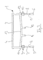
- FIG. 1 shows the part of a component 1 for thermal insulation that is essential to the invention shown, namely a U-shaped rail 2, which is used for fixing and fixing the position of tensile reinforcement bars 3 against an insulating body (not shown) serves, which is crossed by the tension rods.
- the U-rail is there from a U-base 4 and two U-legs 5 and 6, the circular recesses 7, 8 for the tension rods.
- the U-legs 5, 6 each extend on the side surfaces of the insulating body along its longitudinal extent and are oriented vertically, while the U-base is horizontal in the longitudinal direction of the insulator runs.
- the two U-legs 5, 6 are separate from the rest of the rail 2 retaining strips formed, which are provided on the U-base via locking connections 9, 10 Receiving sections 11, 12 are connected. About these rest connections it is possible to first equip the tension rods with the holding strips 5, 6 and then the entirety of tension rods and retaining strips on the U-rail set.
- a connecting bar 13 is provided parallel to the U-base 4, which is arched downward in the unloaded initial state. From this connecting bar 13, two projections extend in the form of Stop bars 14, 15 vertically downwards, where they are later inserted by the Tension bars applied and in the course of mounting the retaining strips in the receptacles be pressed elastically up until the final state shown in Figure 1 is reached in which the connecting bar 13 parallel without curvature extends to the U base 4.
- the reinforcement bar shown in Figure 1 3 from the stop bars 14, 15 down against the lower edges 16, 17 of the recesses 7, 8, which are provided in the holding strips 5, 6 are.
- each reinforcement bar is made of a total of four linear ones Sections acted on and so permanently and securely on the rail 2 and thus set in component 1 for thermal insulation.
- FIG. 2 is an enlarged detail the receptacle 12 for the retaining bar 6 shows and shows how the locking connection 10 is constructed:
- the receptacle 12 is approximately U-shaped with two barb - like, inwardly projecting lower edges, which the of inserted at the bottom and at its upper end, which acts on the receptacle arrow-shaped retaining bar.
- the present invention makes it easy to assemble and yet highly resilient position fixation for reinforcement bars and in particular provided for tension bars, the reinforcement bars between several Parts of the rail used are clamped.
Landscapes
- Engineering & Computer Science (AREA)
- Architecture (AREA)
- Physics & Mathematics (AREA)
- Electromagnetism (AREA)
- Civil Engineering (AREA)
- Structural Engineering (AREA)
- Reinforcement Elements For Buildings (AREA)
- Building Environments (AREA)
- Insulated Conductors (AREA)
- Macromolecular Compounds Obtained By Forming Nitrogen-Containing Linkages In General (AREA)
- Door And Window Frames Mounted To Openings (AREA)
- Wing Frames And Configurations (AREA)
Abstract
Description
- Figur 1
- ein erfindungsgemäßes Bauelement zur Wärmedämmung auszugsweise in Seitenansicht;
- Figur 2
- ein Detail des Bauelementes zur Wärmedämmung aus Figur 1; und
- Figur 3
- das Bauelement aus Figur 1 in der Ausgangsstellung ohne eingesteckte Bewehrungsstäbe.
Claims (17)
- Bauelement zur Wärmedämmung zwischen zwei Bauteilen, insbesondere zwischen einem Gebäude und einem vorkragenden Außenteil, wobei das Bauelement aus einem in der Fuge zwischen den beiden Bauteilen anzuordnenden Isolierkörper mit integrierten Bewehrungsstäben (3) besteht, die sich quer zum Isolierkörper durch diesen hindurch erstrecken, und aus zumindest einer Schiene (2) aus härterem Material als der Isolierkörper, die an oder nahe ihren beiden den Bauteilen zugewandten Seiten Ausnehmungen (7, 8) für die Bewehrungsstäbe aufweist, wobei die Schiene im Bereich zwischen jeweils den beiden Ausnehmungen für einen Bewehrungsstab einen ein Gegenlager für den Bewehrungsstab bildenden Vorsprung (14, 15) aufweist,
dadurch gekennzeichnet, dass die Ausnehmungen (7, 8) eine geschlossene Außenkontur aufweisen, dass sich der Vorsprung (14, 15) im Ausgangszustand ohne Bewehrungsstab (3) so weit in die Flucht der beiden Ausnehmungen erstreckt, dass er diese Flucht teilweise verdeckt, und dass der eingesteckte Bewehrungsstab unter Verdrängung des Vorsprungs (14, 15) aus der Flucht zwischen den Rändern (16, 17) der Ausnehmungen und dem Vorsprung (14, 15) verspannt und festgelegt ist. - Bauelement zur Wärmedämmung nach Anspruch 1
dadurch gekennzeichnet, dass der Vorsprung (14, 15) aus einer sich in Längsrichtung der Schiene (2) erstreckenden Anschlagleiste besteht, und dass die Anschlagleiste elastisch nachgiebig ausgeführt ist. - Bauelement zur Wärmedämmung nach Anspruch 2,
dadurch gekennzeichnet, dass die Anschlagleiste (14, 15) in Vertikalrichtung und senkrecht zur der Erstreckung der Bewehrungsstäbe (3) orientiert ist. - Bauelement zur Wärmedämmung nach einem der vorstehend angeführten Ansprüche,
dadurch gekennzeichnet, dass der Vorsprung aus einem elastisch und/oder plastisch nachgiebigen Material besteht. - Bauelement zur Wärmedämmung nach einem der vorstehend angeführten Ansprüche,
dadurch gekennzeichnet, dass das elastisch und/oder plastisch nachgiebige Material Gummi oder Isolierschaum ist. - Bauelement zur Wärmedämmung nach einem der vorstehend angeführten Ansprüche,
dadurch gekennzeichnet, dass die Schiene (2) einen U-förmigen Querschnitt aufweist, dass die U-Schiene mit ihrer Basis (4) und ihren Schenkeln (5, 6) den Isolierkörper zumindest in Teilen umgibt, und dass die Ausnehmungen (7, 8) jeweils in den Schenkeln der U-Schiene angeordnet sind. - Bauelement zur Wärmedämmung nach einem der vorstehend angeführten Ansprüche,
dadurch gekennzeichnet, dass die Schiene (2) mehrteilig ausgebildet ist derart, dass die Ausnehmungen in separaten Halteleisten (5, 6) vorgesehen sind, und dass die Halteleisten an einer gemeinsamen Schienenbasis (4) festgelegt sind. - Bauelement zur Wärmedämmung nach Anspruch 7,
dadurch gekennzeichnet, dass die Festlegung der Halteleisten (5, 6) an der Schienenbasis (4) über eine Rast-, Schweiß- oder Klebeverbindung (9, 10) erfolgt. - Bauelement zur Wärmedämmung nach einem der vorstehend angeführten Ansprüche,
dadurch gekennzeichnet, dass die Schiene (2) aus zwei U-Schenkeln (5, 6) und einer U-Basis (4) besteht, und dass zusätzlich zur U-Basis eine an die beiden U-Schenkel angeschlossene Verbindungsleiste (13) vorgesehen ist. - Bauelement zur Wärmedämmung nach Anspruch 9,
dadurch gekennzeichnet, dass die Verbindungsleiste (13) den Vorsprung (14, 15) trägt. - Bauelement zur Wärmedämmung nach Anspruch 10 und nach den Ansprüchen 2 und 3,
dadurch gekennzeichnet, dass die Verbindungsleiste (13) zwei parallel zueinander verlaufende Anschlagleisten (14, 15) trägt. - Bauelement zur Wärmedämmung nach zumindest Anspruch 9,
dadurch gekennzeichnet, dass die Verbindungsleiste (13) gewölbt ausgeführt ist und dass die elastische Nachgiebigkeit des Vorsprungs (14, 15) durch die Wölbung der Verbindungsleiste zur Verfügung gestellt wird. - Bauelement zur Wärmedämmung nach einem der vorstehend angeführten Ansprüche,
dadurch gekennzeichnet, dass der Vorsprung (14, 15) unter Vorspannung an dem Bewehrungsstab (3) anliegt, ihn aufgrund der Vorspannung gegen den Rand (16, 17) der Ausnehmungen (7, 8) drückt und so unverschiebbar festlegt. - Bauelement zur Wärmedämmung nach Anspruch 9,
dadurch gekennzeichnet, dass der Bereich zwischen U-Basis (4) und Verbindungsleiste (13) mit Isoliermaterial ausgefüllt ist. - Bauelement zur Wärmedämmung nach Anspruch 9,
dadurch gekennzeichnet, dass sich die Verbindungsleiste (13) in etwa parallel zur U-Basis (4) erstreckt, - Bauelement zur Wärmedämmung nach einem der vorstehend angeführten Ansprüche,
dadurch gekennzeichnet, dass die Ausnehmungen (7, 8) aus dem Querschnitt der Bewehrungsstäbe (3) angepassten und insbesondere runden Bohrungen bestehen. - Bauelement nach Anspruch 3,
dadurch gekennzeichnet, dass die Halteleisten (5, 6) aus anderem und insbesondere weicherem und festerem Material als die Schiene (2) besteht, welche aus demgegenüber steifem Material ausgebildet ist.
Applications Claiming Priority (2)
| Application Number | Priority Date | Filing Date | Title |
|---|---|---|---|
| DE10036525 | 2000-07-27 | ||
| DE10036525A DE10036525A1 (de) | 2000-07-27 | 2000-07-27 | Bauelement zur Wärmedämmung |
Publications (3)
| Publication Number | Publication Date |
|---|---|
| EP1176263A2 true EP1176263A2 (de) | 2002-01-30 |
| EP1176263A3 EP1176263A3 (de) | 2003-01-08 |
| EP1176263B1 EP1176263B1 (de) | 2005-03-16 |
Family
ID=7650358
Family Applications (1)
| Application Number | Title | Priority Date | Filing Date |
|---|---|---|---|
| EP01115445A Expired - Lifetime EP1176263B1 (de) | 2000-07-27 | 2001-06-27 | Bauelement zur Wärmedämmung |
Country Status (3)
| Country | Link |
|---|---|
| EP (1) | EP1176263B1 (de) |
| AT (1) | ATE291132T1 (de) |
| DE (2) | DE10036525A1 (de) |
Citations (1)
| Publication number | Priority date | Publication date | Assignee | Title |
|---|---|---|---|---|
| DE29807381U1 (de) | 1998-04-23 | 1998-08-13 | Schöck Bauteile GmbH, 76534 Baden-Baden | Bauelement zur Wärmedämmung |
Family Cites Families (2)
| Publication number | Priority date | Publication date | Assignee | Title |
|---|---|---|---|---|
| DE4423413A1 (de) * | 1994-07-05 | 1996-01-11 | Schoeck Bauteile Gmbh | Bauelement zur Wärmedämmung bei Gebäuden |
| DE19731093B4 (de) * | 1997-07-19 | 2004-07-15 | Schöck Bauteile GmbH | Bauelement zur Wärmedämmung |
-
2000
- 2000-07-27 DE DE10036525A patent/DE10036525A1/de not_active Withdrawn
-
2001
- 2001-06-27 EP EP01115445A patent/EP1176263B1/de not_active Expired - Lifetime
- 2001-06-27 AT AT01115445T patent/ATE291132T1/de active
- 2001-06-27 DE DE50105594T patent/DE50105594D1/de not_active Expired - Lifetime
Patent Citations (1)
| Publication number | Priority date | Publication date | Assignee | Title |
|---|---|---|---|---|
| DE29807381U1 (de) | 1998-04-23 | 1998-08-13 | Schöck Bauteile GmbH, 76534 Baden-Baden | Bauelement zur Wärmedämmung |
Also Published As
| Publication number | Publication date |
|---|---|
| EP1176263B1 (de) | 2005-03-16 |
| DE50105594D1 (de) | 2005-04-21 |
| DE10036525A1 (de) | 2002-02-07 |
| ATE291132T1 (de) | 2005-04-15 |
| EP1176263A3 (de) | 2003-01-08 |
Similar Documents
| Publication | Publication Date | Title |
|---|---|---|
| CH676615A5 (de) | ||
| EP1832690A2 (de) | Bauelement zur Wärmedämmung | |
| AT4958U1 (de) | Vorrichtung zum abstützen von fenster- oder türrahmen an der begrenzung einer wandöffnung | |
| DE102011122589A1 (de) | Bauelement zur Wärmedämmung | |
| EP0831183B1 (de) | Bauelement zur Wärmedämmung | |
| CH678204A5 (de) | ||
| DE4102332A1 (de) | Balkonanschluss | |
| DE19543768A1 (de) | Balkonanschluß | |
| DE102009003869A1 (de) | Steckverbinder | |
| EP0834622B1 (de) | Wärmegedämmtes Verbindungselement zwischen externen Betonteilen, insbesondere Kragplatten, und Gebäude | |
| EP0778389B1 (de) | Linearverbinder aus Kunstoff für hohle Abstandhalterprofile von Mehrscheibenisoliergläsern | |
| DE102006032444A1 (de) | Bauelement zur Wärmedämmung | |
| EP0599051A1 (de) | Abstützteil für Glasscheiben von Fenstern, Türen od. dgl. | |
| EP1176263B1 (de) | Bauelement zur Wärmedämmung | |
| DE29602634U1 (de) | Isolierscheibe mit zwischen den Glasscheiben eingelegten Hohlsprossen | |
| DE102019118363B4 (de) | Anordnung zum Verbinden eines Bauwerkteils mit einem dem Bauwerkteil vorgelagerten Stahl-Außenteil | |
| DE8129873U1 (de) | Rohrhalterung | |
| DE3525347A1 (de) | Zum halten von heizrohren einer fussbodenheizung bestimmter halteclip | |
| EP1878840B1 (de) | Bauelement zur Wärmedämmung zwischen zwei zu betonierenden Bauteilen | |
| EP1830029A2 (de) | Lamellenanordnung für Fassaden | |
| EP0745733A1 (de) | Kragplatten- und/oder Fugenelement für bewehrte baukonstruktionen | |
| AT408364B (de) | Schalungssystem für ein mantelbeton-mauerwerk | |
| EP1754840B1 (de) | Bauelement zur Wärmedämmung | |
| DE29808988U1 (de) | Glasfalzeinlage | |
| DE202025102353U1 (de) | Anschlagvorrichtung |
Legal Events
| Date | Code | Title | Description |
|---|---|---|---|
| PUAI | Public reference made under article 153(3) epc to a published international application that has entered the european phase |
Free format text: ORIGINAL CODE: 0009012 |
|
| AK | Designated contracting states |
Kind code of ref document: A2 Designated state(s): AT BE CH CY DE DK ES FI FR GB GR IE IT LI LU MC NL PT SE TR |
|
| AX | Request for extension of the european patent |
Free format text: AL;LT;LV;MK;RO;SI |
|
| PUAL | Search report despatched |
Free format text: ORIGINAL CODE: 0009013 |
|
| AK | Designated contracting states |
Kind code of ref document: A3 Designated state(s): AT BE CH CY DE DK ES FI FR GB GR IE IT LI LU MC NL PT SE TR |
|
| AX | Request for extension of the european patent |
Free format text: AL;LT;LV;MK;RO;SI |
|
| 17P | Request for examination filed |
Effective date: 20030212 |
|
| AKX | Designation fees paid |
Designated state(s): AT BE CH CY DE DK ES FI FR GB GR IE IT LI LU MC NL PT SE TR |
|
| 17Q | First examination report despatched |
Effective date: 20031230 |
|
| GRAP | Despatch of communication of intention to grant a patent |
Free format text: ORIGINAL CODE: EPIDOSNIGR1 |
|
| RAP1 | Party data changed (applicant data changed or rights of an application transferred) |
Owner name: SCHOECK BAUTEILE GMBH |
|
| GRAS | Grant fee paid |
Free format text: ORIGINAL CODE: EPIDOSNIGR3 |
|
| GRAA | (expected) grant |
Free format text: ORIGINAL CODE: 0009210 |
|
| AK | Designated contracting states |
Kind code of ref document: B1 Designated state(s): AT BE CH CY DE DK ES FI FR GB GR IE IT LI LU MC NL PT SE TR |
|
| PG25 | Lapsed in a contracting state [announced via postgrant information from national office to epo] |
Ref country code: FI Free format text: LAPSE BECAUSE OF FAILURE TO SUBMIT A TRANSLATION OF THE DESCRIPTION OR TO PAY THE FEE WITHIN THE PRESCRIBED TIME-LIMIT Effective date: 20050316 Ref country code: TR Free format text: LAPSE BECAUSE OF FAILURE TO SUBMIT A TRANSLATION OF THE DESCRIPTION OR TO PAY THE FEE WITHIN THE PRESCRIBED TIME-LIMIT Effective date: 20050316 |
|
| REG | Reference to a national code |
Ref country code: GB Ref legal event code: FG4D Free format text: NOT ENGLISH |
|
| REG | Reference to a national code |
Ref country code: CH Ref legal event code: EP |
|
| REG | Reference to a national code |
Ref country code: IE Ref legal event code: FG4D Free format text: GERMAN |
|
| REF | Corresponds to: |
Ref document number: 50105594 Country of ref document: DE Date of ref document: 20050421 Kind code of ref document: P |
|
| PG25 | Lapsed in a contracting state [announced via postgrant information from national office to epo] |
Ref country code: DK Free format text: LAPSE BECAUSE OF FAILURE TO SUBMIT A TRANSLATION OF THE DESCRIPTION OR TO PAY THE FEE WITHIN THE PRESCRIBED TIME-LIMIT Effective date: 20050616 Ref country code: GR Free format text: LAPSE BECAUSE OF FAILURE TO SUBMIT A TRANSLATION OF THE DESCRIPTION OR TO PAY THE FEE WITHIN THE PRESCRIBED TIME-LIMIT Effective date: 20050616 |
|
| PG25 | Lapsed in a contracting state [announced via postgrant information from national office to epo] |
Ref country code: CY Free format text: LAPSE BECAUSE OF FAILURE TO SUBMIT A TRANSLATION OF THE DESCRIPTION OR TO PAY THE FEE WITHIN THE PRESCRIBED TIME-LIMIT Effective date: 20050627 Ref country code: ES Free format text: LAPSE BECAUSE OF FAILURE TO SUBMIT A TRANSLATION OF THE DESCRIPTION OR TO PAY THE FEE WITHIN THE PRESCRIBED TIME-LIMIT Effective date: 20050627 |
|
| PG25 | Lapsed in a contracting state [announced via postgrant information from national office to epo] |
Ref country code: MC Free format text: LAPSE BECAUSE OF NON-PAYMENT OF DUE FEES Effective date: 20050630 |
|
| GBT | Gb: translation of ep patent filed (gb section 77(6)(a)/1977) |
Effective date: 20050630 |
|
| PG25 | Lapsed in a contracting state [announced via postgrant information from national office to epo] |
Ref country code: PT Free format text: LAPSE BECAUSE OF FAILURE TO SUBMIT A TRANSLATION OF THE DESCRIPTION OR TO PAY THE FEE WITHIN THE PRESCRIBED TIME-LIMIT Effective date: 20050907 |
|
| REG | Reference to a national code |
Ref country code: CH Ref legal event code: NV Representative=s name: R. A. EGLI & CO. PATENTANWAELTE |
|
| PLBE | No opposition filed within time limit |
Free format text: ORIGINAL CODE: 0009261 |
|
| STAA | Information on the status of an ep patent application or granted ep patent |
Free format text: STATUS: NO OPPOSITION FILED WITHIN TIME LIMIT |
|
| 26N | No opposition filed |
Effective date: 20051219 |
|
| EN | Fr: translation not filed | ||
| PG25 | Lapsed in a contracting state [announced via postgrant information from national office to epo] |
Ref country code: SE Free format text: LAPSE BECAUSE OF FAILURE TO SUBMIT A TRANSLATION OF THE DESCRIPTION OR TO PAY THE FEE WITHIN THE PRESCRIBED TIME-LIMIT Effective date: 20050616 |
|
| PG25 | Lapsed in a contracting state [announced via postgrant information from national office to epo] |
Ref country code: FR Free format text: LAPSE BECAUSE OF NON-PAYMENT OF DUE FEES Effective date: 20050630 |
|
| PG25 | Lapsed in a contracting state [announced via postgrant information from national office to epo] |
Ref country code: FR Free format text: LAPSE BECAUSE OF NON-PAYMENT OF DUE FEES Effective date: 20050316 |
|
| PGFP | Annual fee paid to national office [announced via postgrant information from national office to epo] |
Ref country code: LU Payment date: 20110622 Year of fee payment: 11 |
|
| PGFP | Annual fee paid to national office [announced via postgrant information from national office to epo] |
Ref country code: IE Payment date: 20120619 Year of fee payment: 12 |
|
| PGFP | Annual fee paid to national office [announced via postgrant information from national office to epo] |
Ref country code: IT Payment date: 20120623 Year of fee payment: 12 |
|
| REG | Reference to a national code |
Ref country code: IE Ref legal event code: MM4A |
|
| PG25 | Lapsed in a contracting state [announced via postgrant information from national office to epo] |
Ref country code: IE Free format text: LAPSE BECAUSE OF NON-PAYMENT OF DUE FEES Effective date: 20130627 |
|
| PG25 | Lapsed in a contracting state [announced via postgrant information from national office to epo] |
Ref country code: IT Free format text: LAPSE BECAUSE OF NON-PAYMENT OF DUE FEES Effective date: 20130627 |
|
| PG25 | Lapsed in a contracting state [announced via postgrant information from national office to epo] |
Ref country code: LU Free format text: LAPSE BECAUSE OF NON-PAYMENT OF DUE FEES Effective date: 20130627 |
|
| PGFP | Annual fee paid to national office [announced via postgrant information from national office to epo] |
Ref country code: DE Payment date: 20200507 Year of fee payment: 20 |
|
| PGFP | Annual fee paid to national office [announced via postgrant information from national office to epo] |
Ref country code: BE Payment date: 20200622 Year of fee payment: 20 Ref country code: GB Payment date: 20200625 Year of fee payment: 20 Ref country code: NL Payment date: 20200622 Year of fee payment: 20 |
|
| PGFP | Annual fee paid to national office [announced via postgrant information from national office to epo] |
Ref country code: AT Payment date: 20200618 Year of fee payment: 20 |
|
| PGFP | Annual fee paid to national office [announced via postgrant information from national office to epo] |
Ref country code: CH Payment date: 20200630 Year of fee payment: 20 |
|
| REG | Reference to a national code |
Ref country code: DE Ref legal event code: R071 Ref document number: 50105594 Country of ref document: DE |
|
| REG | Reference to a national code |
Ref country code: NL Ref legal event code: MK Effective date: 20210626 Ref country code: CH Ref legal event code: PL |
|
| REG | Reference to a national code |
Ref country code: BE Ref legal event code: MK Effective date: 20210627 |
|
| REG | Reference to a national code |
Ref country code: GB Ref legal event code: PE20 Expiry date: 20210626 |
|
| REG | Reference to a national code |
Ref country code: AT Ref legal event code: MK07 Ref document number: 291132 Country of ref document: AT Kind code of ref document: T Effective date: 20210627 |
|
| PG25 | Lapsed in a contracting state [announced via postgrant information from national office to epo] |
Ref country code: GB Free format text: LAPSE BECAUSE OF EXPIRATION OF PROTECTION Effective date: 20210626 |