EP1176320B1 - Dispositif ainsi que son utilisation pour fixer de manière amovible au moins un élément plat - Google Patents
Dispositif ainsi que son utilisation pour fixer de manière amovible au moins un élément plat Download PDFInfo
- Publication number
- EP1176320B1 EP1176320B1 EP01113289A EP01113289A EP1176320B1 EP 1176320 B1 EP1176320 B1 EP 1176320B1 EP 01113289 A EP01113289 A EP 01113289A EP 01113289 A EP01113289 A EP 01113289A EP 1176320 B1 EP1176320 B1 EP 1176320B1
- Authority
- EP
- European Patent Office
- Prior art keywords
- accordance
- surface element
- holding
- recess
- connecting device
- Prior art date
- Legal status (The legal status is an assumption and is not a legal conclusion. Google has not performed a legal analysis and makes no representation as to the accuracy of the status listed.)
- Expired - Lifetime
Links
- 239000011521 glass Substances 0.000 claims description 31
- 230000007704 transition Effects 0.000 claims description 20
- 239000004033 plastic Substances 0.000 claims description 14
- 239000002184 metal Substances 0.000 claims description 7
- 229910052751 metal Inorganic materials 0.000 claims description 7
- 239000000956 alloy Substances 0.000 claims description 4
- 229910045601 alloy Inorganic materials 0.000 claims description 4
- 238000005192 partition Methods 0.000 claims description 4
- 229910001369 Brass Inorganic materials 0.000 claims description 3
- NIXOWILDQLNWCW-UHFFFAOYSA-N acrylic acid group Chemical group C(C=C)(=O)O NIXOWILDQLNWCW-UHFFFAOYSA-N 0.000 claims description 3
- 229920000122 acrylonitrile butadiene styrene Polymers 0.000 claims description 3
- 239000010951 brass Substances 0.000 claims description 3
- 239000003365 glass fiber Substances 0.000 claims description 3
- 229920000515 polycarbonate Polymers 0.000 claims description 3
- 239000004417 polycarbonate Substances 0.000 claims description 3
- 229920000728 polyester Polymers 0.000 claims description 3
- 229920006324 polyoxymethylene Polymers 0.000 claims description 3
- 230000002787 reinforcement Effects 0.000 claims description 3
- BFKJFAAPBSQJPD-UHFFFAOYSA-N tetrafluoroethene Chemical group FC(F)=C(F)F BFKJFAAPBSQJPD-UHFFFAOYSA-N 0.000 claims description 3
- 229910000831 Steel Inorganic materials 0.000 claims description 2
- HCHKCACWOHOZIP-UHFFFAOYSA-N Zinc Chemical compound [Zn] HCHKCACWOHOZIP-UHFFFAOYSA-N 0.000 claims description 2
- 229910052782 aluminium Inorganic materials 0.000 claims description 2
- XAGFODPZIPBFFR-UHFFFAOYSA-N aluminium Chemical compound [Al] XAGFODPZIPBFFR-UHFFFAOYSA-N 0.000 claims description 2
- 239000010959 steel Substances 0.000 claims description 2
- 229910052725 zinc Inorganic materials 0.000 claims description 2
- 239000011701 zinc Substances 0.000 claims description 2
- 239000011324 bead Substances 0.000 claims 1
- 238000004140 cleaning Methods 0.000 description 9
- 238000004519 manufacturing process Methods 0.000 description 7
- 238000010276 construction Methods 0.000 description 4
- 239000007788 liquid Substances 0.000 description 4
- 240000002853 Nelumbo nucifera Species 0.000 description 2
- 235000006508 Nelumbo nucifera Nutrition 0.000 description 2
- 235000006510 Nelumbo pentapetala Nutrition 0.000 description 2
- 229930040373 Paraformaldehyde Natural products 0.000 description 2
- 230000006978 adaptation Effects 0.000 description 2
- 230000003749 cleanliness Effects 0.000 description 2
- 239000000428 dust Substances 0.000 description 2
- 230000000694 effects Effects 0.000 description 2
- 238000009434 installation Methods 0.000 description 2
- -1 polyoxymethylene Polymers 0.000 description 2
- 238000004873 anchoring Methods 0.000 description 1
- 230000009286 beneficial effect Effects 0.000 description 1
- LYKJEJVAXSGWAJ-UHFFFAOYSA-N compactone Natural products CC1(C)CCCC2(C)C1CC(=O)C3(O)CC(C)(CCC23)C=C LYKJEJVAXSGWAJ-UHFFFAOYSA-N 0.000 description 1
- 239000002131 composite material Substances 0.000 description 1
- 230000001186 cumulative effect Effects 0.000 description 1
- 238000009826 distribution Methods 0.000 description 1
- 230000003670 easy-to-clean Effects 0.000 description 1
- 239000012530 fluid Substances 0.000 description 1
- 230000002209 hydrophobic effect Effects 0.000 description 1
- 238000012423 maintenance Methods 0.000 description 1
- 239000000463 material Substances 0.000 description 1
- 239000000203 mixture Substances 0.000 description 1
- 239000005871 repellent Substances 0.000 description 1
- 230000000717 retained effect Effects 0.000 description 1
- 239000010935 stainless steel Substances 0.000 description 1
- 229910001220 stainless steel Inorganic materials 0.000 description 1
- 238000003860 storage Methods 0.000 description 1
- 239000000126 substance Substances 0.000 description 1
- 239000002023 wood Substances 0.000 description 1
Images







Classifications
-
- E—FIXED CONSTRUCTIONS
- E06—DOORS, WINDOWS, SHUTTERS, OR ROLLER BLINDS IN GENERAL; LADDERS
- E06B—FIXED OR MOVABLE CLOSURES FOR OPENINGS IN BUILDINGS, VEHICLES, FENCES OR LIKE ENCLOSURES IN GENERAL, e.g. DOORS, WINDOWS, BLINDS, GATES
- E06B3/00—Window sashes, door leaves, or like elements for closing wall or like openings; Layout of fixed or moving closures, e.g. windows in wall or like openings; Features of rigidly-mounted outer frames relating to the mounting of wing frames
- E06B3/54—Fixing of glass panes or like plates
- E06B3/5436—Fixing of glass panes or like plates involving holes or indentations in the pane
- E06B3/5445—Support arms engaging the holes or indentations
-
- E—FIXED CONSTRUCTIONS
- E04—BUILDING
- E04B—GENERAL BUILDING CONSTRUCTIONS; WALLS, e.g. PARTITIONS; ROOFS; FLOORS; CEILINGS; INSULATION OR OTHER PROTECTION OF BUILDINGS
- E04B1/00—Constructions in general; Structures which are not restricted either to walls, e.g. partitions, or floors or ceilings or roofs
- E04B1/38—Connections for building structures in general
- E04B1/61—Connections for building structures in general of slab-shaped building elements with each other
- E04B1/6108—Connections for building structures in general of slab-shaped building elements with each other the frontal surfaces of the slabs connected together
- E04B1/6116—Connections for building structures in general of slab-shaped building elements with each other the frontal surfaces of the slabs connected together by locking means on lateral surfaces
-
- E—FIXED CONSTRUCTIONS
- E05—LOCKS; KEYS; WINDOW OR DOOR FITTINGS; SAFES
- E05D—HINGES OR SUSPENSION DEVICES FOR DOORS, WINDOWS OR WINGS
- E05D5/00—Construction of single parts, e.g. the parts for attachment
- E05D5/02—Parts for attachment, e.g. flaps
- E05D5/0246—Parts for attachment, e.g. flaps for attachment to glass panels
-
- E—FIXED CONSTRUCTIONS
- E06—DOORS, WINDOWS, SHUTTERS, OR ROLLER BLINDS IN GENERAL; LADDERS
- E06B—FIXED OR MOVABLE CLOSURES FOR OPENINGS IN BUILDINGS, VEHICLES, FENCES OR LIKE ENCLOSURES IN GENERAL, e.g. DOORS, WINDOWS, BLINDS, GATES
- E06B3/00—Window sashes, door leaves, or like elements for closing wall or like openings; Layout of fixed or moving closures, e.g. windows in wall or like openings; Features of rigidly-mounted outer frames relating to the mounting of wing frames
- E06B3/02—Wings made completely of glass
-
- E—FIXED CONSTRUCTIONS
- E06—DOORS, WINDOWS, SHUTTERS, OR ROLLER BLINDS IN GENERAL; LADDERS
- E06B—FIXED OR MOVABLE CLOSURES FOR OPENINGS IN BUILDINGS, VEHICLES, FENCES OR LIKE ENCLOSURES IN GENERAL, e.g. DOORS, WINDOWS, BLINDS, GATES
- E06B3/00—Window sashes, door leaves, or like elements for closing wall or like openings; Layout of fixed or moving closures, e.g. windows in wall or like openings; Features of rigidly-mounted outer frames relating to the mounting of wing frames
- E06B3/54—Fixing of glass panes or like plates
- E06B3/5436—Fixing of glass panes or like plates involving holes or indentations in the pane
-
- E—FIXED CONSTRUCTIONS
- E04—BUILDING
- E04B—GENERAL BUILDING CONSTRUCTIONS; WALLS, e.g. PARTITIONS; ROOFS; FLOORS; CEILINGS; INSULATION OR OTHER PROTECTION OF BUILDINGS
- E04B1/00—Constructions in general; Structures which are not restricted either to walls, e.g. partitions, or floors or ceilings or roofs
- E04B1/38—Connections for building structures in general
- E04B1/61—Connections for building structures in general of slab-shaped building elements with each other
- E04B1/6108—Connections for building structures in general of slab-shaped building elements with each other the frontal surfaces of the slabs connected together
- E04B2001/6191—Connections for building structures in general of slab-shaped building elements with each other the frontal surfaces of the slabs connected together by means on the corners of the slabs
-
- E—FIXED CONSTRUCTIONS
- E04—BUILDING
- E04B—GENERAL BUILDING CONSTRUCTIONS; WALLS, e.g. PARTITIONS; ROOFS; FLOORS; CEILINGS; INSULATION OR OTHER PROTECTION OF BUILDINGS
- E04B1/00—Constructions in general; Structures which are not restricted either to walls, e.g. partitions, or floors or ceilings or roofs
- E04B1/38—Connections for building structures in general
- E04B1/61—Connections for building structures in general of slab-shaped building elements with each other
- E04B2001/6195—Connections for building structures in general of slab-shaped building elements with each other the slabs being connected at an angle, e.g. forming a corner
-
- E—FIXED CONSTRUCTIONS
- E05—LOCKS; KEYS; WINDOW OR DOOR FITTINGS; SAFES
- E05D—HINGES OR SUSPENSION DEVICES FOR DOORS, WINDOWS OR WINGS
- E05D5/00—Construction of single parts, e.g. the parts for attachment
- E05D5/02—Parts for attachment, e.g. flaps
- E05D5/0246—Parts for attachment, e.g. flaps for attachment to glass panels
- E05D2005/0253—Parts for attachment, e.g. flaps for attachment to glass panels the panels having conical or stepped recesses
-
- E—FIXED CONSTRUCTIONS
- E05—LOCKS; KEYS; WINDOW OR DOOR FITTINGS; SAFES
- E05D—HINGES OR SUSPENSION DEVICES FOR DOORS, WINDOWS OR WINGS
- E05D5/00—Construction of single parts, e.g. the parts for attachment
- E05D5/02—Parts for attachment, e.g. flaps
- E05D5/0246—Parts for attachment, e.g. flaps for attachment to glass panels
- E05D2005/0261—Parts for attachment, e.g. flaps for attachment to glass panels connecting two or more glass panels
- E05D2005/0269—Parts for attachment, e.g. flaps for attachment to glass panels connecting two or more glass panels the panels being coplanar
-
- E—FIXED CONSTRUCTIONS
- E05—LOCKS; KEYS; WINDOW OR DOOR FITTINGS; SAFES
- E05Y—INDEXING SCHEME ASSOCIATED WITH SUBCLASSES E05D AND E05F, RELATING TO CONSTRUCTION ELEMENTS, ELECTRIC CONTROL, POWER SUPPLY, POWER SIGNAL OR TRANSMISSION, USER INTERFACES, MOUNTING OR COUPLING, DETAILS, ACCESSORIES, AUXILIARY OPERATIONS NOT OTHERWISE PROVIDED FOR, APPLICATION THEREOF
- E05Y2800/00—Details, accessories and auxiliary operations not otherwise provided for
- E05Y2800/15—Applicability
- E05Y2800/16—Applicable on combinations of fixed and movable wings
- E05Y2800/162—Applicable on combinations of fixed and movable wings the wings being coplanar when the movable wing is in the closed position
-
- E—FIXED CONSTRUCTIONS
- E05—LOCKS; KEYS; WINDOW OR DOOR FITTINGS; SAFES
- E05Y—INDEXING SCHEME ASSOCIATED WITH SUBCLASSES E05D AND E05F, RELATING TO CONSTRUCTION ELEMENTS, ELECTRIC CONTROL, POWER SUPPLY, POWER SIGNAL OR TRANSMISSION, USER INTERFACES, MOUNTING OR COUPLING, DETAILS, ACCESSORIES, AUXILIARY OPERATIONS NOT OTHERWISE PROVIDED FOR, APPLICATION THEREOF
- E05Y2900/00—Application of doors, windows, wings or fittings thereof
- E05Y2900/10—Application of doors, windows, wings or fittings thereof for buildings or parts thereof
- E05Y2900/13—Type of wing
- E05Y2900/132—Doors
Definitions
- the invention relates to an arrangement with a device for releasable mounting of at least one surface element and its Use.
- Such devices are well known. However, have Such devices are pronounced in practice as proved disadvantageous. Thus, such devices serve among others as a holder or the like, for example as fittings of glass or plastic panes for shower cubicles etc., which mostly on both sides of the plane of the surfaces of the glass protrude.
- the devices thus represent an undesirable Dust and dirt or moisture trap. Also is a cleaning of a glass sheet in the range of these devices not possible, at least considerably more difficult.
- the glass pane can not be consistent with a rubber lip for removal be removed from cleaning fluid. Rather, it is then to drive around these devices with the rubber lip, possibly even with the consequence that actually be removed Cleaning liquid penetrates into the devices themselves. Also, these are all devices, either not sufficiently stable or a very expensive Construction and large height have. In addition, these devices have the disadvantage that their proportions and dimensions are predetermined and thus not changeable. An individual Adaptation to surface elements with tolerance inaccuracies is therefore not possible with these devices.
- the invention is therefore based on the object, a device for releasably supporting at least one surface element to To provide, with which prevent the above disadvantages which, therefore, a particularly simple cleaning all surfaces of the at least one of the device held surface element allows and at the same time constructive particularly simple, compact and stable, and consequently cost-effective can be produced, without further individual manufacturing inaccuracies the surface elements to be joined together compensates and is extremely easy to assemble and disassemble is, as well as an advantageous use of this device provide.
- the device according to the invention has the essential Advantage, without further dimensional inaccuracies and manufacturing tolerances compensate by their shape and dimensions accordingly The given premises are individually changeable. Not the last result is a pronounced one easy handling during assembly or disassembly. After all is also a cost-effective production and storage of the Device according to the invention allows.
- the at least one holding device comprises two substantially plate-shaped holding elements, of two opposite surfaces of at least a surface element ago in the recess of the surface element can be used and in the recess opposite each other are fastened.
- This way is a reliable one Holder of the associated surface element, as a rule a multiple of the weight of that of the holding device has enabled. Also, this is a simple, fast and reliable mounting of the holding device in the associated Surface element or subsequent dismantling thereof to maintenance or repair purposes.
- the holding element is advantageously with a holding portion and a support portion.
- the holding section essentially serves to secure the holding device in the recess.
- the carrier section is essentially for receiving and holding the holding device and optionally at least part of the connecting device provided in the recess.
- two holding elements of Retaining device according to claim 2 releasably connect to each other.
- a screw because the clamping force or biasing force of screws, for example, in the presence of dimensional inaccuracies etc. is individually adjustable.
- the two retaining elements are advantageously according to the claims 3 and 4 formed.
- the constructive measures of claim 5 ensure a Tolerance compensation caused by manufacturing inaccuracies and / or Dimensional deviations resulting from building measures of premises, in which surface elements are to be connected to each other, may occur.
- the Design support element according to claim 7 ensures that the holding device of the invention Device after completion of form fit by inserting in the corresponding recess additionally by a frictional connection can be secured in the recess. It can thus high forces and moments, in particular by the weight gro- ⁇ er Glass plates are produced, easily safe and reliable be recorded and / or transmitted.
- the connecting device form according to claim 10 rotatably.
- the connecting device be angled according to claim 12. So can the For example, angles may be 90 ° or 135 °.
- connection device To design according to claim 13 rotatable.
- the connection device the device according to the invention is so far provided with a hinge or as a hinge or swivel joint formed such that the at least one surface element opposite another surface element, which expediently is rigid or fixed, relatively twisted or pivoted can be.
- the connecting device designed advantageously, wherein the fastener as a cumulative or alternative measure to the serves to support at least one surface element.
- the feature of claim 15 allows pronounced versatile, also individual and flexible adaptation to spatial Conditions and architectural designs.
- the measures of claim 18 results in a uniform and continuous surface of the device according to the invention with the advantage of simplified cleaning and keeping clean, and in particular even if the surface elements made Glass exist and so far a relatively intense Cleanliness require.
- the outer surface of the two opposing holding elements can either by the chemical material composition of the holding elements, which is designed, for example, hydrophobic achieved become. It is also conceivable, a liquid and / or dirt-repellent surface of the holding elements and / or the entire Overall device to achieve that mechanical Surface patterns or profiles provided in the nano range which are a liability of liquid and / or dirt, etc. counteract. In the latter embodiment, for example the so-called lotus flower effect use.
- a device according to the invention for releasable support of at least one surface element Metal, plastic, wood, glass or a combination thereof use or as a fitting or the like for the assembly of Room dividers, partition walls or other partition elements, glass showcases, Glass landscapes in offices, glass and plastic windows as well as glass and plastic doors, in particular of or for shower or toilet cubicles or similar wet cells, and / or for attachment of components, such as brackets, handles or similar fittings, and the like to use.
- the use of the device according to the invention especially as a fitting leads to the decidedly great advantage glass showcases easy to assemble and disassemble are, so that at any time be transported, their cleaning and cleanliness is very simple, their transparency largely preserved and finally dimensional inaccuracies and manufacturing tolerances readily compensate is.
- the inventive device 10 is for releasable support provided by at least one surface element 12.
- the device according to the invention are corresponding to one another, the same components each provided with identical reference numerals.
- the device 10 according to the invention is suitable for releasable Mounting of at least one surface element 12 made of metal, Plastic, wood, glass and composites thereof.
- At the surface element 12 may be, for example, a sound-absorbing Wall panels made of wood, glass pane, plastic pane etc. and / or a wall of a room, for example a bathroom wall, act.
- the Device 10 according to the invention serves the Device 10 according to the invention as a fitting or the like for the installation of room dividers, glass showcases, glass landscapes in Office space, glass and plastic windows and glass and plastic doors, in particular of or for shower and toilet cabins or the like wet cells, and / or for attachment of Components such as brackets, handles or the like, fittings and the like objects.
- the device 10 according to the invention is also suitable for releasable Mounting of partitions between each two adjacent ones sanitary facilities, such as wash basins, Urinals, toilets, showers etc.
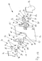
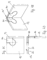
- the surface element 12 of the embodiment of the device 10 For example, as shown in Figs. 1A to 1G, as Glass pane formed a shower or toilet cabin.
- the However, surface element 12 is for simplicity in all Embodiments only shown schematically.
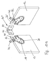
- FIGS. 1A to 2B show a first embodiment of a first embodiment represented such device 10 according to the invention.
- the device 10 comprises at least one connecting device 14, which supports the at least one surface element 12. Especially allows the connection device 14 a connection or fixing the at least one surface element 12 to or on a further surface element 12 and / or additional constructive Components for support.
- the connection device 14 and these additional components for support are hereafter explained in more detail.
- the device 10 has at least one holding device 16, which cooperates with the connecting device 14.
- the holding device 16 In the illustrated embodiment of the device 10 according to FIGS. 1A to 1G is merely a holding device 16 shown. In practice, however, are usually several such holding means 16 for holding the at least one Surface element 12 is provided.
- the connecting device 14 and the holding device 16 of the Device 10 are together via a recess 18 at the respective assigned surface element 12 can be fixed.
- the recess 18, in the embodiment shown in FIGS. 1A to 1G is arranged in a corner region of the surface element 12 includes for this purpose, a clamping portion 18 'to the following recording device 16 to be described in more detail, and a transition section 18 "to one part or the other Part of the holding device 16 and at least a part of Connecting device 14 record.
- the transition section 18 '' extends from the clamping portion 18 'towards a Edge 12 'of the surface element 12, which the / the other Surface element / s 12 faces.
- the at least one holding device 16 is in the recess 18 the surface element 12 positively and / or non-positively fastened.
- the holding device 16 in the recess 18 is such fixed that the at least one holding device 16 with their outer surfaces 20, 20 'in the assembled state or substantially with the planes of the back surface 22 and the front surface 24 of the surface element 12th flees. This is evident in particular from FIG. 1D.
- FIG. 1D On This way is a particularly simple cleaning of the surface element 12 ensured in the assembled state.
- results from such a flush design a extremely beautiful shape of the surface element 12 with the Holding device 16.
- the at least one comprises a holding device 16 two substantially plate-shaped Retaining elements 26, 26 '.
- the plate-shaped holding elements 26, 26 'are of the two opposed to each other facing away surfaces 22, 24 of the surface element 12th forth in the recess 18 of the surface element 12 can be used. in this respect is the holding member 26 in the illustrated in Fig. 1A Embodiment of the back, the holding member 26 'of the Front to the corresponding surfaces 22, 24 of the associated Introduce surface element 12.
- the two holding elements 26, 26 ' which are opposite each other, in shape and dimension adapted to each other.
- the holding elements 26, 26 'are corresponding to FIGS. 1A to 1C each have a holding portion 28, which is substantially the attachment the holding device 16 in the clamping portion 18 'of associated recess 18 is used. Furthermore, the holding elements comprise 26, 26 'corresponding to FIGS. 1A to 1C each one Carrier section 30, which is essentially for receiving and holding the holding device 16 and at least a part of the Connecting device 14 in the transition section 18 '' of the associated Recess 18 is provided. This will be the holding section 28 in the clamping portion 18 'of the corresponding recess 18 recorded. The carrier section 30 is in contrast Receiving in the transition section 18 '' of the associated recess 18th
- the holding portion 28 and the support portion 30 of the two holding elements 26, 26 ' as indicated in FIGS. 1A and 1E, essentially have a thickness d that is slightly smaller as half the thickness D of the surface element 12th
- the two holding elements 26, 26 ' are connected to one another or screwed, via at least one screw 32. Without to be shown in detail, could a screw 32nd approximately in the middle in the holding section 28 of the respective holding element 26, 26 'may be arranged.
- FIG. 1A to 1G four screws 32 are provided, which are the two holding elements 26, 26 'set to each other.
- the four screws 32 are evenly over the holding portion 26 and the support portion 30 of the respective holding element 26, 26 'distributed and arranged mirror-symmetrically to each other.
- FIG. 1A also shows that the one holding element 26 'of the two holding elements 26, 26 'with four holes 34 for receiving the screws 32 provided.
- the other holding element 26 of the two Holding elements 26, 26 ' however, with four threaded holes 36th equipped for locking the screws 32.
- this has a holding element 26 of the two holding elements 26, 26 'a recess or the like recess 38th on, the inclusion of at least a portion of the connecting device 14 serves.
- the other holding element 26 'of the two holding elements 26, 26 ' is connected to the connecting device 14 or a part of it connectable.
- the other holding element 26 ' provided with a bore 40 or the like, which receives a screw 42 (see Fig. 2B and 5A, 5B).
- the Screw 42 is konterbar in a threaded bore 44.
- the threaded hole 44 is located in the at least part of the connecting device 14 for their attachment.
- the longitudinal axis 46 of the elongated hole formed bore 40 extends essentially parallel to an edge 12 'of the surface element 12.
- Such a structural design has the Advantage that when holding the surface element 12 via a Recess 18 in the corner region of the surface element 12 a Compensation of inaccuracies, which, for example, in the Production result, but also by spatial construction conditions are encountered in one direction, namely in the direction of Longitudinal axis 46, is possible.
- Such a construction brings with mutual support of two surface elements 12 in the corner area a further advantage with himself.
- the support element 52 is preferably made of plastic, in particular polyoxymethylene, polyester, ABS, acrylic, polycarbonate, Tetrafluoroethylene or impax, with or without glass-fiber reinforcement, when the surface element 12 is made of glass.
- two are each Support elements 52 between the surface element 12 and the respective Holding element 26, 26 'of the holding device 16 is provided.
- the two support element 52 are identical to one another in this respect and come with their mutually facing backs 54 each in contact. However, without being detailed, it is also conceivable to design the support element 52 in one piece.
- each clamping surfaces 58 the in the embodiment of the device 10 according to FIGS. 1A to 1G cone or cone (dull) are formed.
- the Clamping surfaces 58 of the support elements 52 in turn act accordingly formed clamping surfaces 60 on the inner circumference 62 of the Clamping portion 18 'and the transition portion 18' 'of the respective Recess 18 together.
- clamping surfaces 58 in any way different, for example, hemispherical or dome-shaped and / or rounded off.
- the clamping surfaces 60 would then be shaped accordingly.
- the respective one Support element 52 in its basic form substantially to the Basic shape of a holding element 26 with the recess or adapted to the same recess 38.
- the support element 52 also with a slot 64 or the like recess Mistake.
- the slot 64 divides the support element 52 thereby in two mirror-symmetrically identical halves 66, 66 '.
- a ganwulst or similar edge (increase) 70 is provided, with which the respective associated holding element 26, 26 'over the edges 72 at least partially in contact comes.
- the holding device 16 and the connecting device 14 at least partially by a cover 74 or the same cover can be covered. It is preferred that the outer surfaces of the cover 74 in the mounted state with or substantially with the outer surfaces 22, 24 of the respective surface element 12 are aligned.
- the respective cover element 74 by means of a Snap or the like locking connection on the holding device 16 are attached.
- one or more Latches 76 at the respective holding element 26, 26 'associated Surface of the cover 74 may be provided with the corresponding recesses 78 on the respective holding element 26, 26 'cooperate and can be brought into mutual engagement are.
- a uniform Surface of the surface element 12 together with the invention Device 10 obtained.
- a cleaning of the releasably supported Surface element 12 is thus particularly simple. As well is a buildup of dirt or dust in the area of the device 10 counteracted.
- the holding device 16 and / or the connecting device 14 can depending on the use, application and customer requirements made of metal, such as (non-rusting) Steel, stainless steel, aluminum, brass, zinc, gunmetal alloys or an alloy thereof, to be arbitrary to absorb and support large forces. That's the way it works in the surface element 12 shown schematically in all Usually by a surface element of larger dimensions with inevitable large weight forces, such as in the case of a Glass pane or glass door opening from the device 10 after the Invention is to be kept.
- metal such as (non-rusting) Steel, stainless steel, aluminum, brass, zinc, gunmetal alloys or an alloy thereof
- the holding device 16 and / or the connecting device 14 or at least parts thereof made of plastic, for example Polyoxymethylene, polyester, ABS, acrylic, polycarbonate, tetrafluoroethylene or Impax, with or without glass fiber reinforcement, manufacture.
- plastic for example Polyoxymethylene, polyester, ABS, acrylic, polycarbonate, tetrafluoroethylene or Impax, with or without glass fiber reinforcement, manufacture.
- connection means 14 formed rotationally fixed.
- the connecting device 14 essentially plate, web or the like band-shaped.
- the structural design of the connection device 14 corresponding to FIGS. 2A and 2B is shown in FIG. 3A again reproduced in detail.
- the connecting device 14 also in of any other form, depending on the needs, Requirements and spatial conditions. So is the connecting device 14 according to the Fig. 3B substantially designed as a square plate.
- the connection device 14 according to FIG. 3C is L-shaped, wherein the two legs have the same length. Likewise, it is conceivable, one of the two legs with a To provide length that is greater than that of the other Leg.
- the connecting device 14 according to FIG. 3D finally has T-shape.
- the connecting means 14 are therefore Although differently shaped, but each plate-shaped designed.
- the connecting devices extend 14 each in a common plane.
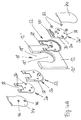
- the embodiment of the device 10 according to the invention which in 4A to 5B is substantially the same as that shown in Figs FIGS. 1A to 2B coincide.
- the only difference is the shape of the recess 18 in the surface element 12. Accordingly Are the individual components to the modified Basic shape of the recess 18 adapted.
- the different shape and dimension of the recess 18 results from the fact that the recess is not in a corner region of the surface element 12th formed, but is provided in a straight edge region.
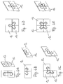
- FIGS. 6A to 6E schematically show various connection possibilities several surface elements 12 to each other.
- FIG. 6A two surface elements 12 are in FIG a straight edge region shown. Suitable for this purpose a connecting device 14 according to FIG. 3A.
- FIG. 6B two surface elements 12 are each in one Corner area shown.
- FIG. 3A two surface elements 12 are shown, which together are connected or held over the corner area.
- a connection device is suitable 14 according to FIG. 3C.
- Fig. 6D are two Surface elements 12 held together over the corner area and additionally with a surface element 12 in the straight edge region connected.
- a T-shaped connecting device 14 accordingly of Fig. 3D is suitable.
- Fig. 6E is a possibility shown, a total of four surface elements 12 in the respective corner area to each other to fix.
- a connection device 14 accordingly of Fig. 3B suitable suitable.
- Such an angled connecting device 14 ' is, for example in the embodiment of the device 10 according to Figs. 7A to 7D realized. Otherwise, the embodiment is correct 7A to 7D with that of FIGS. 1A to 2B match.
- the connecting device 14 ' is in the embodiment according to the Fig. 7D designed such that the two in At an angle of 90 ° arranged surface elements 12 slightly spaced apart from each other. So there is a small gap 80 between the edge 12 'of the one surface element 12 and the front surface 24 of the other surface element 12 available.
- This gap 80 is arbitrarily changeable, i. can be scaled down to zero or arbitrary be enlarged.
- connection means 14 ' which are substantially angled in each case, shown.
- the connecting device 14 'according to the Fig. 8A corresponds to those already in connection with the embodiment of the device 10 of FIG. 7A to 7D is explained.
- Fig. 8B is a connection means 14 ', which are not at an angle of 90 °, but angled from 130 °.
- FIG. 8D is an angled connecting device 14 ', which at the same time T-shaped is designed.
- Such a connection device 14 ' is suitable for example for separating several side by side lying shower or toilet cubicles.
- FIGS. 8D to 8G Connecting devices 14, 14 ' are substantially identical with those of Figs. 3A and 8A to 8C.
- These connecting devices 14, 14 'each for holding a surface element 12 at one another surface element 12 in the form of, for example, a Wall element or a wall of a bathroom or the like is provided.
- FIGS. 9A to 9D of one or more surface elements 12 further surface elements 12 shown schematically.
- FIGS. 9A, 9B and 9D are in each case connections or holders shown between two surface elements 12 made of glass.
- 9C a surface element 12 made of glass directly on a surface element 12 in the form of a wall of a Room screwed.
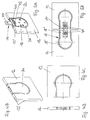
- FIGS. 10A to 10D another embodiment of the Device 10 according to the invention. This is different from that of FIGS. 7A to 7D only in that the connecting device 14 '' with a hinge 84 provided or configured as a rotary joint 84.
- a surface element 12 the is immovable, with a surface element 12, opposite the fixed surface element 12 is relatively rotatable, such as to connect a door to a shower or toilet cabin.
- FIGs. 11A to 11D are still other embodiments shown by connecting means 14 '' '.
- a fastener 86 for (additional) support of at least a surface element 12 on another surface element 12th or the like attached.
- the fastener 86 is thereby facing away from the at least one surface element 12 and advantageously in the plane of the at least one surface element 12 arranged.
- the fastener 86 in the embodiment of Fig. 11A designed as a pin or pin 88.
- the bolt or pin 88 can in a corresponding hole or Sleeve, for example, in a ceiling or on the floor, intervene. Consequently, both surface elements 12 are relatively rotatable not only to each other, but in addition to the room designed.
- the pin or pin 88 ensures an additional anchoring and thus for an increase of Stability.
- the fastener 86 is another Section 90, which includes an eye 92 over which the two surface elements 12 at a continuous Rod 94 can be fixed.
- FIG. 11C shows a fastening element 86, in which the connecting device 14 '' 'with a hinge 84 is equipped and an extended portion 96th to, for example, the surface element 12 via two Holes 98 on the further surface element 12 in the form of a To turn wall.
- the fastener 86 is on the connector 14 '' 'with an extended portion 100 provided, which is angled end to the two to each other relatively rotatable surface elements 12, for example the ceiling or floor (not shown), i. depend or réellemenrn.
- FIGS. 1A to 11D have the two holding elements 26, 26 'of at least a holding device 16 and the connecting device 14 is substantially a thickness d, which added together slightly is smaller than the thickness D of the surface element 12th is.
- the thickness of the connecting device 14 should accordingly selected the male holding forces and on the thicknesses of the holding elements 26, 26 'as well as the support elements 52 adapted to the thickness D of the surface element 12 possible not to exceed. In this way it is ensured that the at least one holding device 16 with the outer surfaces 20, 20 'in the assembled state in Substantially with the planes of the surfaces 22, 24 of at least a surface element 12 coincide.
- FIGS. 12A to 12D are still different Embodiments of recesses 18 shown.
- the clamping portion 18 'of the recess 18 in the embodiment 12A through a bore 102 in the surface element 12 formed, wherein the circumferential angle ⁇ greater than 180 ° is.
- the transition portion 18 '' of the recess 18 is formed by a further bore 104.
- the clear distance e the transition section 18 '' of the recess 18 can thereby be equal to or greater than the diameter of the clamping portion 18 'of the recesses 18, i. as the diameter of the hole 102nd
- transition portion 18 "of the recesses 18 also according to the embodiment of FIG. 12B (Aus) be cut.
- FIG. 12C is the transition section 18 "of FIG Recesses 18 while tangential (off) cut or how From Fig. 12D shows tangential (off) cut and additionally broken in edge regions 108.
- the two opposing holding elements 26, 26 'and / or the cover 74 each with an outer surface 20, 20 'is formed corresponding to the so-called lotus blossom effect liquid and / or stain resistant.
Landscapes
- Engineering & Computer Science (AREA)
- Civil Engineering (AREA)
- Structural Engineering (AREA)
- Architecture (AREA)
- Physics & Mathematics (AREA)
- Electromagnetism (AREA)
- Mechanical Engineering (AREA)
- Connection Of Plates (AREA)
- Clamps And Clips (AREA)
- Mechanical Coupling Of Light Guides (AREA)
- Mechanical Treatment Of Semiconductor (AREA)
- Casings For Electric Apparatus (AREA)
- Snaps, Bayonet Connections, Set Pins, And Snap Rings (AREA)
- Adornments (AREA)
- Moulds For Moulding Plastics Or The Like (AREA)
- Measurement Of The Respiration, Hearing Ability, Form, And Blood Characteristics Of Living Organisms (AREA)
Claims (28)
- Disposition avec un dispositif (10) pour maintenir de façon mobile au moins un élément de surface (12) et avec au moins un élément de surface (12) comprenant au moins un dispositif de liaison (14, 14', 14'', 14''') fixant au moins un élément de surface (12) et comprenant au moins un dispositif de maintien (16) coopérant avec le dispositif de liaison (14, 14', 14'', 14''') qui peut être fixé sur au moins un élément de surface (12) via un évidement (18) associé à au moins un élément de surface (12), caractérisé en ce qu'au moins un dispositif de maintien (16) avec ses surfaces (20, 20') se trouvant à l'extérieur dans l'état de montage est aligné avec les plans des surfaces supérieures (22, 24) d'au moins un élément de surface (12), l'évidement (18) d'au moins un élément de surface (12) comprenant un tronçon de serrage (18') et un tronçon de transition (18'') s'étendant à partir du tronçon de serrage (18') vers un rebord (12') orienté vers au moins un élément de surface (12) pour recevoir le dispositif de maintien (16) et éventuellement au moins d'une partie du dispositif de liaison (14, 14', 14'', 14''') et où au moins un dispositif de maintien (16) comprend deux éléments de maintien (26, 26') essentiellement en forme de plaques qui peuvent être installés à partir de deux surfaces supérieures (22, 24) se faisant face de l'élément de surface (12) dans l'évidement (18) de l'élément de surface (12) et peuvent être fixés en se faisant face dans l'évidement (18).
- Dispositif selon la revendication 1, caractérisé en ce que les deux éléments de maintien (26, 26') sont susceptibles d'être reliés ensemble, notamment vissés.
- Dispositif selon la revendication 1 ou 2, caractérisé en ce qu'un (26) des deux éléments de maintien (26, 26') est pourvu d'un évidement ou une saignée (38) similaire pour la réception d'au moins une partie du dispositif de liaison (14).
- Dispositif selon une des revendications 1 à 3, caractérisé en ce que l'autre élément (26') des deux éléments de maintien (26, 26') est pourvu d'un alésage (40) ou quelque chose de similaire pour la réception d'une vis (42) qui peut être centrée dans un alésage de filetage (44) dans au moins une partie du dispositif de liaison (14) pour être fixée.
- Dispositif selon la revendication 4, caractérisé en ce que l'alésage (40) de l'autre élément (26') des deux éléments de maintien (26, 26') est formé en tant que trou oblong dont l'axe longitudinal (46) s'étend essentiellement de manière parallèle par rapport à un bord (12') de l'élément de surface (12).
- Dispositif selon une des revendications 1 à 5, caractérisé en ce qu'entre au moins un élément de surface (12) et au moins un dispositif de maintien (16), on a disposé un élément d'appui (52) en matière plastique, notamment en polyoximéthylène, en polyester, ABS, en acrylique, en polycarbonate, en tetrafluoréthylène ou en impax, avec ou sans renforcement de fibres de verre.
- Dispositif selon la revendication 6, caractérisé en ce que l'élément d'appui (52) présente une surface de serrage (58) quelque peu en forme de demi-sphère, de calotte, de cône, respectivement de cône obtus ou quelque chose de similaire et/ou arrondie, ladite surface étant disposée sur la circonférence extérieure (56) de l'élément d'appui, laquelle surface de serrage coopère avec une surface de serrage (60) formée de façon correspondante sur la circonférence intérieure (62) de l'évidement (18).
- Dispositif selon la revendication 6 ou 7, caractérisé en ce que l'élément d'appui (52) présente une fente (64) divisant l'élément d'appui (52) en deux moitiés (66, 66') symétriques.
- Dispositif selon une des revendications 6 à 8, caractérisé en ce que l'élément d'appui (52) présente un bourrelet d'application ou une bordure (70) similaire pour la réception de chaque élément de maintien (26, 26').
- Dispositif selon une des revendications 1 à 9, caractérisé en ce que le dispositif de liaison (14) est formé de manière immobile en rotation.
- Dispositif selon une des revendications 1 à 10, caractérisé en ce que le dispositif de liaison (14) est formé de manière plane, notamment sous forme de plaque essentiellement, en forme de L ou en forme de T.
- Dispositif selon une des revendications 1 à 11, caractérisé en ce que le dispositif de liaison (14') est plié.
- Dispositif selon une des revendications 1 à 12, caractérisé en ce que le dispositif de liaison (14'') est pourvu d'une articulation rotative (84).
- Dispositif selon une des revendications 1 à 13, caractérisé en ce que le dispositif de liaison (14''') comprend un élément de fixation (86) détourné d'au moins un élément de surface (12), disposé dans le plan d'au moins un élément de surface (12) afin de maintenir au moins un élément de surface (12) sur un autre élément de surface (12).
- Dispositif selon la revendication 14, caractérisé en ce que l'élément de fixation (86) est formé en tant que boulon ou pivot (88) un autre tronçon (90, 96, 100) ou languette similaire.
- Dispositif selon une des revendications 1 à 15, caractérisé en ce que le dispositif de maintien (16) et/ou le dispositif de liaison (14, 14', 14'', 14''') est en métal, notamment, un acier (inoxydable), aluminium, laiton, zinc, des liages composés de cuivre, étain, zinc et plomb ou des alliages formés par des métaux précédents.
- Dispositif selon une des revendications 1 à 16, caractérisé en ce que les deux éléments de maintien (26, 26') d'au moins un dispositif de maintien (16) et le dispositif de liaison (14, 14', 14", 14''') présentent essentiellement une épaisseur (d) qui au total est légèrement plus petite, identique ou légèrement plus grosse que l'épaisseur (D) de l'élément de surface (12).
- Dispositif selon une des revendications 1 à 17, caractérisé en ce que le dispositif de maintien (16) et le dispositif de liaison (14, 14', 14'', 14''') sont susceptibles d'être recouverts par un élément de recouvrement (74) ou un couvercle similaire, de manière à ce que leurs surfaces se trouvant à l'extérieur sont alignées dans l'état de montage, essentiellement avec les surfaces supérieures (22, 24) se trouvant à l'extérieur de l'élément de surface (12).
- Dispositif selon une des revendications 1 à 18, caractérisé en ce que le dispositif de maintien (16) et/ou le dispositif de liaison (14, 14', 14'', 14''') et/ou l'élément de recouvrement (74) est/sont formé(s) par une surface imperméable et/ou insalissable se trouvant à l'extérieur.
- Dispositif selon une des revendications 1 à 19, caractérisé en ce que le tronçon de serrage (18') de l'évidement (18) est formée par un alésage (102), l'angle de circonférence α', respectivement, α étant égal ou supérieur à 180°.
- Dispositif selon une des revendications 1 à 20, caractérisé en ce que le tronçon de transition (18'') de l'évidement (18) est formé par un autre alésage (104).
- Dispositif selon une des revendications 1 à 20, caractérisé en ce que le tronçon de transition (18'') de l'évidement (18) est découpé.
- Dispositif selon une des revendications 1 à 20, caractérisé en ce que le tronçon de transition (18'') de l'évidement (18) est découpé de façon tangentielle.
- Dispositif selon la revendication 23, caractérisé en ce que les zones de bord (108) du tronçon de transition (18'') découpé de façon tangentielle de l'évidement (18) sont brisées.
- Dispositif selon une des revendications 21 à 24, caractérisé en ce que l'étendue (e') du tronçon de transition (18'') de l'évidement (18) est inférieure au diamètre du tronçon de serrage (18') de l'évidement (18), lorsque l'angle de circonférence α' est égal à 180°.
- Dispositif selon une des revendications 21 à 24, caractérisé en ce que l'étendue (e) du tronçon de transition (18'') de l'évidement (18) est égale ou supérieure au diamètre du tronçon de serrage (18') de l'évidement (18), lorsque l'angle de circonférence α est supérieur à 180°.
- Utilisation d'un dispositif selon une des revendications précédentes pour maintenir de façon mobile au moins un élément de surface (12) en métal, en matière plastique, en bois, en verre ou selon une combinaison de ces matières sur un autre élément de surface (12) et/ou un autre élément de paroi.
- Utilisation d'un dispositif selon une des revendications précédentes en tant que garniture ou quelque chose de similaire pour monter des séparateurs d'espace, des parois de séparation ou d'autres éléments de séparation, des vitrines en verre, des espaces en verre dans les bureaux, des vitres en verre ou en matière plastique ainsi que des portes en verre et en matière plastique, notamment de cabines de douche ou de toilettes ou des cellules sanitaires similaires et/ou pour fixer des éléments de construction, comme des supports, des poignées ou des armatures similaires, et des objets similaires.
Applications Claiming Priority (2)
| Application Number | Priority Date | Filing Date | Title |
|---|---|---|---|
| DE10027896A DE10027896C2 (de) | 2000-06-06 | 2000-06-06 | Vorrichtung zur lösbaren Halterung von wenigstens zwei Flächenelementen und deren Verwendung |
| DE10027896 | 2000-06-06 |
Publications (3)
| Publication Number | Publication Date |
|---|---|
| EP1176320A2 EP1176320A2 (fr) | 2002-01-30 |
| EP1176320A3 EP1176320A3 (fr) | 2002-10-30 |
| EP1176320B1 true EP1176320B1 (fr) | 2005-08-24 |
Family
ID=7644805
Family Applications (1)
| Application Number | Title | Priority Date | Filing Date |
|---|---|---|---|
| EP01113289A Expired - Lifetime EP1176320B1 (fr) | 2000-06-06 | 2001-05-31 | Dispositif ainsi que son utilisation pour fixer de manière amovible au moins un élément plat |
Country Status (4)
| Country | Link |
|---|---|
| EP (1) | EP1176320B1 (fr) |
| AT (1) | ATE302912T1 (fr) |
| DE (3) | DE10027896C2 (fr) |
| ES (1) | ES2248194T3 (fr) |
Cited By (1)
| Publication number | Priority date | Publication date | Assignee | Title |
|---|---|---|---|---|
| EP4606287A1 (fr) * | 2024-02-23 | 2025-08-27 | C.R. Laurence Co., Inc. | Ensemble de serrage de panneau de verre amélioré |
Families Citing this family (4)
| Publication number | Priority date | Publication date | Assignee | Title |
|---|---|---|---|---|
| DE10052420C2 (de) * | 2000-10-23 | 2003-10-02 | Joachim Fischbach | Vorrichtung zur lösbaren Halterung von wenigstens zwei Flächenelementen und deren Verwendung |
| DE10211709C1 (de) * | 2002-03-16 | 2003-11-06 | Paul Jean Munch | Duschkabine mit einer wenigstens eine Glasplatte aufweisenden Duschtrennwand |
| DE10356748B4 (de) * | 2003-12-04 | 2006-06-08 | Joachim Fischbach | Vorrichtung zur lösbaren Halterung von wenigstens einem Flächenelement und deren Verwendung |
| EP2530227B1 (fr) * | 2011-05-31 | 2013-05-29 | Provex Industrie GmbH | Charnière à fixations affleurantes pour éléments de vitrerie |
Citations (2)
| Publication number | Priority date | Publication date | Assignee | Title |
|---|---|---|---|---|
| US5348778A (en) * | 1991-04-12 | 1994-09-20 | Bayer Aktiengesellschaft | Sandwich elements in the form of slabs, shells and the like |
| EP0841032A2 (fr) * | 1996-11-12 | 1998-05-13 | Joachim Fischbach | Dispositif pour la fixation réglable des panneaux, en particulier panneaux de verre ou similaires |
Family Cites Families (3)
| Publication number | Priority date | Publication date | Assignee | Title |
|---|---|---|---|---|
| FR1352781A (fr) * | 1963-04-17 | 1964-02-14 | Paleari Attilio E C | Charnière en particulier pour portes en verre |
| DE2827220A1 (de) * | 1978-06-21 | 1980-01-10 | Herbert Lehmann | Verbindungselement fuer flache konstruktionsteile |
| DE4236919C2 (de) * | 1992-10-31 | 1995-04-06 | Henke Paul Gmbh & Co Kg | Verbindungsbeschlag zur Verbindung von Möbelteilen |
-
2000
- 2000-06-06 DE DE10027896A patent/DE10027896C2/de not_active Expired - Lifetime
-
2001
- 2001-05-31 AT AT01113289T patent/ATE302912T1/de active
- 2001-05-31 ES ES01113289T patent/ES2248194T3/es not_active Expired - Lifetime
- 2001-05-31 EP EP01113289A patent/EP1176320B1/fr not_active Expired - Lifetime
- 2001-05-31 DE DE50107179T patent/DE50107179D1/de not_active Expired - Lifetime
- 2001-05-31 DE DE50107177T patent/DE50107177D1/de not_active Expired - Lifetime
Patent Citations (2)
| Publication number | Priority date | Publication date | Assignee | Title |
|---|---|---|---|---|
| US5348778A (en) * | 1991-04-12 | 1994-09-20 | Bayer Aktiengesellschaft | Sandwich elements in the form of slabs, shells and the like |
| EP0841032A2 (fr) * | 1996-11-12 | 1998-05-13 | Joachim Fischbach | Dispositif pour la fixation réglable des panneaux, en particulier panneaux de verre ou similaires |
Cited By (1)
| Publication number | Priority date | Publication date | Assignee | Title |
|---|---|---|---|---|
| EP4606287A1 (fr) * | 2024-02-23 | 2025-08-27 | C.R. Laurence Co., Inc. | Ensemble de serrage de panneau de verre amélioré |
Also Published As
| Publication number | Publication date |
|---|---|
| DE10027896C2 (de) | 2002-08-01 |
| ES2248194T3 (es) | 2006-03-16 |
| EP1176320A3 (fr) | 2002-10-30 |
| DE50107177D1 (de) | 2005-09-29 |
| DE50107179D1 (de) | 2005-09-29 |
| DE10027896A1 (de) | 2002-01-03 |
| ATE302912T1 (de) | 2005-09-15 |
| EP1176320A2 (fr) | 2002-01-30 |
Similar Documents
| Publication | Publication Date | Title |
|---|---|---|
| EP1020575B1 (fr) | Connection en T entre un poteau et une traverse profilés d'une façade ou d'une toiture vitrée | |
| DE3200310A1 (de) | Gestell aus mehreren profilstaeben | |
| EP1984582B1 (fr) | Plafond intérieur suspendu et éléments composant celui-ci | |
| DE102006016045A1 (de) | Vorrichtung zur lösbaren Halterung von einem Flächenelement und deren Verwendung | |
| DE4311468C1 (de) | Haltestange zum Halten und/oder Aussteifen von Trennwänden für Duschkabinen | |
| EP1176320A2 (fr) | Dispositif ainsi que son utilisation pour fixer de manière amovible au moins un élément plat | |
| WO2005071178A1 (fr) | Dispositif de fixation amovible d'au moins un element plat, systeme comprenant au moins deux de ces dispositifs, et leur utilisation | |
| EP1428964B1 (fr) | Ensemble avec au moins un élément plat et un dispositif pour fixer de manière amovible ledit au moins élément plat ainsi que son utilisation | |
| DE19614307A1 (de) | Einseitig flache Glashalterung | |
| DE10356748B4 (de) | Vorrichtung zur lösbaren Halterung von wenigstens einem Flächenelement und deren Verwendung | |
| DE60023812T2 (de) | Schienenabschnitt zum Anbringen und Befestigen von Badezimmerarmaturen, Küchenarmaturen oder dergleichen | |
| EP1170514B1 (fr) | Dispositif ainsi que son utilisation pour fixer de manière amovible au moins deux éléments plats | |
| EP2721963B1 (fr) | Agencement de liaison d'un meuble siège, meuble siège et procédé de montage | |
| DE10052420C2 (de) | Vorrichtung zur lösbaren Halterung von wenigstens zwei Flächenelementen und deren Verwendung | |
| DE10044969A1 (de) | Wandprofilleiste | |
| EP0528255A1 (fr) | Jeu de construction pour cadres comprenant des profilés creux et des connecteurs de coins | |
| DE4438026C1 (de) | Trennwand für Duschen | |
| DE102007057293A1 (de) | Wandbefestigungsprofil für eine Duschwand und damit ausgestattete Dusche | |
| DE202007000574U1 (de) | Wandbefestigungsprofil für eine Duschwand und damit ausgstattete Dusche | |
| DE102006016022B4 (de) | Vorrichtung zur drehbaren Halterung von zwei Flächenelementen und deren Verwendung | |
| DE10113503C2 (de) | Vorrichtung zur lösbaren Halterung von wenigstens zwei Flächenlementen und deren Verwendung | |
| EP0539424B1 (fr) | Rail profile | |
| DE202018104585U1 (de) | Haltevorrichtung für eine Glasscheibe sowie Halteanordnung und Glaswandanordnung | |
| DE10135112B4 (de) | Konstruktionssystem zur Herstellung von Baugruppen, wie Wand-,Boden-oder Deckenkonstruktionen | |
| DE3827574C2 (fr) |
Legal Events
| Date | Code | Title | Description |
|---|---|---|---|
| PUAI | Public reference made under article 153(3) epc to a published international application that has entered the european phase |
Free format text: ORIGINAL CODE: 0009012 |
|
| AK | Designated contracting states |
Kind code of ref document: A2 Designated state(s): AT BE CH CY DE DK ES FI FR GB GR IE IT LI LU MC NL PT SE TR |
|
| AX | Request for extension of the european patent |
Free format text: AL;LT;LV;MK;RO;SI |
|
| PUAL | Search report despatched |
Free format text: ORIGINAL CODE: 0009013 |
|
| AK | Designated contracting states |
Kind code of ref document: A3 Designated state(s): AT BE CH CY DE DK ES FI FR GB GR IE IT LI LU MC NL PT SE TR |
|
| AX | Request for extension of the european patent |
Free format text: AL;LT;LV;MK;RO;SI |
|
| 17P | Request for examination filed |
Effective date: 20030127 |
|
| 17Q | First examination report despatched |
Effective date: 20030422 |
|
| AKX | Designation fees paid |
Designated state(s): AT BE CH CY DE DK ES FI FR GB GR IE IT LI LU MC NL PT SE TR |
|
| GRAP | Despatch of communication of intention to grant a patent |
Free format text: ORIGINAL CODE: EPIDOSNIGR1 |
|
| GRAP | Despatch of communication of intention to grant a patent |
Free format text: ORIGINAL CODE: EPIDOSNIGR1 |
|
| GRAS | Grant fee paid |
Free format text: ORIGINAL CODE: EPIDOSNIGR3 |
|
| GRAA | (expected) grant |
Free format text: ORIGINAL CODE: 0009210 |
|
| AK | Designated contracting states |
Kind code of ref document: B1 Designated state(s): AT BE CH CY DE DK ES FI FR GB GR IE IT LI LU MC NL PT SE TR |
|
| PG25 | Lapsed in a contracting state [announced via postgrant information from national office to epo] |
Ref country code: FI Free format text: LAPSE BECAUSE OF FAILURE TO SUBMIT A TRANSLATION OF THE DESCRIPTION OR TO PAY THE FEE WITHIN THE PRESCRIBED TIME-LIMIT Effective date: 20050824 Ref country code: IE Free format text: LAPSE BECAUSE OF FAILURE TO SUBMIT A TRANSLATION OF THE DESCRIPTION OR TO PAY THE FEE WITHIN THE PRESCRIBED TIME-LIMIT Effective date: 20050824 |
|
| REG | Reference to a national code |
Ref country code: GB Ref legal event code: FG4D Free format text: NOT ENGLISH |
|
| BECA | Be: change of holder's address |
Owner name: *FISCHBACH JOACHIM Effective date: 20050824 Owner name: BISCHOF-SPROLL-WEG15, DE-88212 RAVENSBURG (DE) Effective date: 20050824 Owner name: ZOGENFELDSTRASSE 16, DE-88214 RAVENSBURG Effective date: 20050824 Owner name: *FISCHBACH OLIVER Effective date: 20050824 |
|
| BECH | Be: change of holder |
Owner name: *FISCHBACH OLIVER Effective date: 20050824 Owner name: *FISCHBACH JOACHIM Effective date: 20050824 |
|
| REG | Reference to a national code |
Ref country code: CH Ref legal event code: EP |
|
| REG | Reference to a national code |
Ref country code: IE Ref legal event code: FG4D Free format text: LANGUAGE OF EP DOCUMENT: GERMAN |
|
| REF | Corresponds to: |
Ref document number: 50107179 Country of ref document: DE Date of ref document: 20050929 Kind code of ref document: P |
|
| PG25 | Lapsed in a contracting state [announced via postgrant information from national office to epo] |
Ref country code: SE Free format text: LAPSE BECAUSE OF FAILURE TO SUBMIT A TRANSLATION OF THE DESCRIPTION OR TO PAY THE FEE WITHIN THE PRESCRIBED TIME-LIMIT Effective date: 20051124 Ref country code: DK Free format text: LAPSE BECAUSE OF FAILURE TO SUBMIT A TRANSLATION OF THE DESCRIPTION OR TO PAY THE FEE WITHIN THE PRESCRIBED TIME-LIMIT Effective date: 20051124 Ref country code: GR Free format text: LAPSE BECAUSE OF FAILURE TO SUBMIT A TRANSLATION OF THE DESCRIPTION OR TO PAY THE FEE WITHIN THE PRESCRIBED TIME-LIMIT Effective date: 20051124 |
|
| RAP2 | Party data changed (patent owner data changed or rights of a patent transferred) |
Owner name: FISCHBACH, JOACHIM Owner name: MUELLER, ELMAR Owner name: FISCHBACH, OLIVER Owner name: LEITGEB, PETER |
|
| ET | Fr: translation filed | ||
| GBT | Gb: translation of ep patent filed (gb section 77(6)(a)/1977) |
Effective date: 20051221 |
|
| REG | Reference to a national code |
Ref country code: CH Ref legal event code: NV Representative=s name: ISLER & PEDRAZZINI AG |
|
| PG25 | Lapsed in a contracting state [announced via postgrant information from national office to epo] |
Ref country code: PT Free format text: LAPSE BECAUSE OF FAILURE TO SUBMIT A TRANSLATION OF THE DESCRIPTION OR TO PAY THE FEE WITHIN THE PRESCRIBED TIME-LIMIT Effective date: 20060124 |
|
| NLS | Nl: assignments of ep-patents |
Owner name: OLIVER FISCHBACH Effective date: 20051111 Owner name: JOACHIM FISCHBACH Effective date: 20051111 |
|
| NLT2 | Nl: modifications (of names), taken from the european patent patent bulletin |
Owner name: FISCHBACH, JOACHIM EN FISCHBACH, OLIVER Effective date: 20051130 |
|
| REG | Reference to a national code |
Ref country code: ES Ref legal event code: FG2A Ref document number: 2248194 Country of ref document: ES Kind code of ref document: T3 |
|
| REG | Reference to a national code |
Ref country code: IE Ref legal event code: FD4D |
|
| PG25 | Lapsed in a contracting state [announced via postgrant information from national office to epo] |
Ref country code: MC Free format text: LAPSE BECAUSE OF NON-PAYMENT OF DUE FEES Effective date: 20060531 |
|
| PLBE | No opposition filed within time limit |
Free format text: ORIGINAL CODE: 0009261 |
|
| STAA | Information on the status of an ep patent application or granted ep patent |
Free format text: STATUS: NO OPPOSITION FILED WITHIN TIME LIMIT |
|
| RAP2 | Party data changed (patent owner data changed or rights of a patent transferred) |
Owner name: FISCHBACH, JOACHIM Owner name: LEITGEB, PETER Owner name: FISCHBACH, OLIVER Owner name: MUELLER, ELMAR |
|
| 26N | No opposition filed |
Effective date: 20060526 |
|
| NLT2 | Nl: modifications (of names), taken from the european patent patent bulletin |
Owner name: FISCHBACH, JOACHIM EN FISCHBACH, OLIVER Effective date: 20060719 |
|
| PGFP | Annual fee paid to national office [announced via postgrant information from national office to epo] |
Ref country code: BE Payment date: 20070524 Year of fee payment: 7 |
|
| REG | Reference to a national code |
Ref country code: CH Ref legal event code: PCAR Free format text: ISLER & PEDRAZZINI AG;POSTFACH 1772;8027 ZUERICH (CH) |
|
| BECA | Be: change of holder's address |
Owner name: ZOGENFELDSTRASSE 16, DE-88214 RAVENSBURG Effective date: 20050824 Owner name: BISCHOF-SPROLL-WEG15, DE-88212 RAVENSBURG (DE) Effective date: 20050824 Owner name: *FISCHBACH OLIVER Effective date: 20050824 Owner name: *FISCHBACH JOACHIM Effective date: 20050824 |
|
| BECH | Be: change of holder |
Owner name: *FISCHBACH JOACHIM Effective date: 20050824 Owner name: *FISCHBACH OLIVER Effective date: 20050824 |
|
| PGFP | Annual fee paid to national office [announced via postgrant information from national office to epo] |
Ref country code: FR Payment date: 20070518 Year of fee payment: 7 |
|
| PG25 | Lapsed in a contracting state [announced via postgrant information from national office to epo] |
Ref country code: LU Free format text: LAPSE BECAUSE OF NON-PAYMENT OF DUE FEES Effective date: 20060531 Ref country code: TR Free format text: LAPSE BECAUSE OF FAILURE TO SUBMIT A TRANSLATION OF THE DESCRIPTION OR TO PAY THE FEE WITHIN THE PRESCRIBED TIME-LIMIT Effective date: 20050824 |
|
| PGFP | Annual fee paid to national office [announced via postgrant information from national office to epo] |
Ref country code: ES Payment date: 20080523 Year of fee payment: 8 |
|
| PGFP | Annual fee paid to national office [announced via postgrant information from national office to epo] |
Ref country code: IT Payment date: 20080524 Year of fee payment: 8 |
|
| PGFP | Annual fee paid to national office [announced via postgrant information from national office to epo] |
Ref country code: NL Payment date: 20080523 Year of fee payment: 8 |
|
| PG25 | Lapsed in a contracting state [announced via postgrant information from national office to epo] |
Ref country code: CY Free format text: LAPSE BECAUSE OF FAILURE TO SUBMIT A TRANSLATION OF THE DESCRIPTION OR TO PAY THE FEE WITHIN THE PRESCRIBED TIME-LIMIT Effective date: 20050824 |
|
| BERE | Be: lapsed |
Owner name: *FISCHBACH JOACHIM Effective date: 20080531 Owner name: *FISCHBACH OLIVER Effective date: 20080531 |
|
| PGFP | Annual fee paid to national office [announced via postgrant information from national office to epo] |
Ref country code: GB Payment date: 20080522 Year of fee payment: 8 |
|
| REG | Reference to a national code |
Ref country code: FR Ref legal event code: ST Effective date: 20090119 |
|
| PG25 | Lapsed in a contracting state [announced via postgrant information from national office to epo] |
Ref country code: BE Free format text: LAPSE BECAUSE OF NON-PAYMENT OF DUE FEES Effective date: 20080531 |
|
| PG25 | Lapsed in a contracting state [announced via postgrant information from national office to epo] |
Ref country code: FR Free format text: LAPSE BECAUSE OF NON-PAYMENT OF DUE FEES Effective date: 20080602 |
|
| GBPC | Gb: european patent ceased through non-payment of renewal fee |
Effective date: 20090531 |
|
| NLV4 | Nl: lapsed or anulled due to non-payment of the annual fee |
Effective date: 20091201 |
|
| PG25 | Lapsed in a contracting state [announced via postgrant information from national office to epo] |
Ref country code: NL Free format text: LAPSE BECAUSE OF NON-PAYMENT OF DUE FEES Effective date: 20091201 |
|
| PG25 | Lapsed in a contracting state [announced via postgrant information from national office to epo] |
Ref country code: GB Free format text: LAPSE BECAUSE OF NON-PAYMENT OF DUE FEES Effective date: 20090531 |
|
| REG | Reference to a national code |
Ref country code: ES Ref legal event code: FD2A Effective date: 20090601 |
|
| PG25 | Lapsed in a contracting state [announced via postgrant information from national office to epo] |
Ref country code: ES Free format text: LAPSE BECAUSE OF NON-PAYMENT OF DUE FEES Effective date: 20090601 |
|
| PG25 | Lapsed in a contracting state [announced via postgrant information from national office to epo] |
Ref country code: IT Free format text: LAPSE BECAUSE OF NON-PAYMENT OF DUE FEES Effective date: 20090531 |
|
| PGFP | Annual fee paid to national office [announced via postgrant information from national office to epo] |
Ref country code: CH Payment date: 20110525 Year of fee payment: 11 |
|
| PGFP | Annual fee paid to national office [announced via postgrant information from national office to epo] |
Ref country code: AT Payment date: 20110520 Year of fee payment: 11 |
|
| REG | Reference to a national code |
Ref country code: CH Ref legal event code: PL |
|
| REG | Reference to a national code |
Ref country code: AT Ref legal event code: MM01 Ref document number: 302912 Country of ref document: AT Kind code of ref document: T Effective date: 20120531 |
|
| PG25 | Lapsed in a contracting state [announced via postgrant information from national office to epo] |
Ref country code: LI Free format text: LAPSE BECAUSE OF NON-PAYMENT OF DUE FEES Effective date: 20120531 Ref country code: AT Free format text: LAPSE BECAUSE OF NON-PAYMENT OF DUE FEES Effective date: 20120531 Ref country code: CH Free format text: LAPSE BECAUSE OF NON-PAYMENT OF DUE FEES Effective date: 20120531 |
|
| REG | Reference to a national code |
Ref country code: DE Ref legal event code: R082 Ref document number: 50107179 Country of ref document: DE Representative=s name: GRAPE & SCHWARZENSTEINER, DE Ref country code: DE Ref legal event code: R081 Ref document number: 50107179 Country of ref document: DE Owner name: FISCHBACH, JOACHIM, DE Free format text: FORMER OWNER: JOACHIM FISCHBACH,OLIVER FISCHBACH,PETER LEITGEB,ELMAR MUELLER, , AT Ref country code: DE Ref legal event code: R081 Ref document number: 50107179 Country of ref document: DE Owner name: FISCHBACH, OLIVER, DE Free format text: FORMER OWNER: JOACHIM FISCHBACH,OLIVER FISCHBACH,PETER LEITGEB,ELMAR MUELLER, , AT Ref country code: DE Ref legal event code: R081 Ref document number: 50107179 Country of ref document: DE Owner name: FISCHBACH, JOACHIM, DE Free format text: FORMER OWNERS: FISCHBACH, JOACHIM, 88214 RAVENSBURG, DE; FISCHBACH, OLIVER, 88212 RAVENSBURG, DE; LEITGEB, PETER, TELFES, AT; MUELLER, ELMAR, NEUSTIFT, AT Ref country code: DE Ref legal event code: R081 Ref document number: 50107179 Country of ref document: DE Owner name: FISCHBACH, OLIVER, DE Free format text: FORMER OWNERS: FISCHBACH, JOACHIM, 88214 RAVENSBURG, DE; FISCHBACH, OLIVER, 88212 RAVENSBURG, DE; LEITGEB, PETER, TELFES, AT; MUELLER, ELMAR, NEUSTIFT, AT |
|
| PGFP | Annual fee paid to national office [announced via postgrant information from national office to epo] |
Ref country code: DE Payment date: 20200217 Year of fee payment: 20 |
|
| REG | Reference to a national code |
Ref country code: DE Ref legal event code: R071 Ref document number: 50107179 Country of ref document: DE |