EP1176334A2 - Amortisseur à variation continue actionné par un soleinoide - Google Patents
Amortisseur à variation continue actionné par un soleinoide Download PDFInfo
- Publication number
- EP1176334A2 EP1176334A2 EP01117501A EP01117501A EP1176334A2 EP 1176334 A2 EP1176334 A2 EP 1176334A2 EP 01117501 A EP01117501 A EP 01117501A EP 01117501 A EP01117501 A EP 01117501A EP 1176334 A2 EP1176334 A2 EP 1176334A2
- Authority
- EP
- European Patent Office
- Prior art keywords
- shock absorber
- valve
- chamber
- compression
- working chamber
- Prior art date
- Legal status (The legal status is an assumption and is not a legal conclusion. Google has not performed a legal analysis and makes no representation as to the accuracy of the status listed.)
- Granted
Links
- 239000006096 absorbing agent Substances 0.000 title claims abstract description 60
- 230000035939 shock Effects 0.000 title claims abstract description 60
- 239000012530 fluid Substances 0.000 claims abstract description 67
- 238000004891 communication Methods 0.000 claims abstract description 12
- 230000006835 compression Effects 0.000 abstract description 84
- 238000007906 compression Methods 0.000 abstract description 84
- 238000013016 damping Methods 0.000 description 52
- 239000000725 suspension Substances 0.000 description 7
- 238000004804 winding Methods 0.000 description 4
- 230000008901 benefit Effects 0.000 description 3
- 230000009977 dual effect Effects 0.000 description 3
- 230000007246 mechanism Effects 0.000 description 3
- 230000001276 controlling effect Effects 0.000 description 2
- 230000005284 excitation Effects 0.000 description 2
- 230000004075 alteration Effects 0.000 description 1
- 238000010276 construction Methods 0.000 description 1
- 230000008602 contraction Effects 0.000 description 1
- 238000010586 diagram Methods 0.000 description 1
- 230000004069 differentiation Effects 0.000 description 1
- 238000006073 displacement reaction Methods 0.000 description 1
- 238000000034 method Methods 0.000 description 1
- 230000004048 modification Effects 0.000 description 1
- 238000012986 modification Methods 0.000 description 1
- 230000001105 regulatory effect Effects 0.000 description 1
- 230000004044 response Effects 0.000 description 1
- 238000000926 separation method Methods 0.000 description 1
- 238000011144 upstream manufacturing Methods 0.000 description 1
Images


Classifications
-
- F—MECHANICAL ENGINEERING; LIGHTING; HEATING; WEAPONS; BLASTING
- F16—ENGINEERING ELEMENTS AND UNITS; GENERAL MEASURES FOR PRODUCING AND MAINTAINING EFFECTIVE FUNCTIONING OF MACHINES OR INSTALLATIONS; THERMAL INSULATION IN GENERAL
- F16F—SPRINGS; SHOCK-ABSORBERS; MEANS FOR DAMPING VIBRATION
- F16F9/00—Springs, vibration-dampers, shock-absorbers, or similarly-constructed movement-dampers using a fluid or the equivalent as damping medium
- F16F9/32—Details
- F16F9/44—Means on or in the damper for manual or non-automatic adjustment; such means combined with temperature correction
- F16F9/46—Means on or in the damper for manual or non-automatic adjustment; such means combined with temperature correction allowing control from a distance, i.e. location of means for control input being remote from site of valves, e.g. on damper external wall
- F16F9/465—Means on or in the damper for manual or non-automatic adjustment; such means combined with temperature correction allowing control from a distance, i.e. location of means for control input being remote from site of valves, e.g. on damper external wall using servo control, the servo pressure being created by the flow of damping fluid, e.g. controlling pressure in a chamber downstream of a pilot passage
-
- F—MECHANICAL ENGINEERING; LIGHTING; HEATING; WEAPONS; BLASTING
- F16—ENGINEERING ELEMENTS AND UNITS; GENERAL MEASURES FOR PRODUCING AND MAINTAINING EFFECTIVE FUNCTIONING OF MACHINES OR INSTALLATIONS; THERMAL INSULATION IN GENERAL
- F16F—SPRINGS; SHOCK-ABSORBERS; MEANS FOR DAMPING VIBRATION
- F16F9/00—Springs, vibration-dampers, shock-absorbers, or similarly-constructed movement-dampers using a fluid or the equivalent as damping medium
- F16F9/06—Springs, vibration-dampers, shock-absorbers, or similarly-constructed movement-dampers using a fluid or the equivalent as damping medium using both gas and liquid
-
- F—MECHANICAL ENGINEERING; LIGHTING; HEATING; WEAPONS; BLASTING
- F16—ENGINEERING ELEMENTS AND UNITS; GENERAL MEASURES FOR PRODUCING AND MAINTAINING EFFECTIVE FUNCTIONING OF MACHINES OR INSTALLATIONS; THERMAL INSULATION IN GENERAL
- F16F—SPRINGS; SHOCK-ABSORBERS; MEANS FOR DAMPING VIBRATION
- F16F9/00—Springs, vibration-dampers, shock-absorbers, or similarly-constructed movement-dampers using a fluid or the equivalent as damping medium
- F16F9/32—Details
- F16F9/34—Special valve constructions; Shape or construction of throttling passages
- F16F9/348—Throttling passages in the form of annular discs or other plate-like elements which may or may not have a spring action, operating in opposite directions or singly, e.g. annular discs positioned on top of the valve or piston body
-
- F—MECHANICAL ENGINEERING; LIGHTING; HEATING; WEAPONS; BLASTING
- F16—ENGINEERING ELEMENTS AND UNITS; GENERAL MEASURES FOR PRODUCING AND MAINTAINING EFFECTIVE FUNCTIONING OF MACHINES OR INSTALLATIONS; THERMAL INSULATION IN GENERAL
- F16F—SPRINGS; SHOCK-ABSORBERS; MEANS FOR DAMPING VIBRATION
- F16F9/00—Springs, vibration-dampers, shock-absorbers, or similarly-constructed movement-dampers using a fluid or the equivalent as damping medium
- F16F9/32—Details
- F16F9/44—Means on or in the damper for manual or non-automatic adjustment; such means combined with temperature correction
- F16F9/46—Means on or in the damper for manual or non-automatic adjustment; such means combined with temperature correction allowing control from a distance, i.e. location of means for control input being remote from site of valves, e.g. on damper external wall
- F16F9/464—Control of valve bias or pre-stress, e.g. electromagnetically
Definitions
- the present invention relates to a hydraulic damper or shock absorber adapted for use in a suspension system such as the suspension systems used for automotive vehicles. More particularly, the present invention relates to a hydraulic damper or shock absorber having a continuously variable damping characteristic which is adjustable by a solenoid actuated continuously variable servo valve to vary the damping characteristics between a relatively low level of damping for a soft ride for comfort and a relatively high level of damping for a firm ride for handling.
- a conventional prior art hydraulic damper or shock absorber comprises a cylinder which is adapted at one end for attachment to the unsprung mass of a vehicle.
- a piston is slidably disposed within the cylinder with the piston separating the interior of the cylinder into two fluid chambers.
- a piston rod is connected to the piston and extends out of one end of the cylinder where it is adapted for attachment to the sprung mass of the vehicle.
- adjustment mechanisms have been developed to generate variable damping forces in relation to the speed and/or the amplitude of the displacement of the sprung mass in relation to the unsprung mass.
- These adjustment mechanisms have mainly been developed to provide a relatively small or low damping characteristic during the normal steady state running of the vehicle and a relatively large or high damping characteristic during vehicle maneuvers requiring extended suspension movements.
- the normal steady state running of the vehicle is accompanied by small or fine vibrations of the unsprung mass of the vehicle and thus the need for a soft ride or low damping characteristic of the suspension system to isolate the sprung mass from these small vibrations.
- the sprung mass of the vehicle will attempt to undergo a relatively slow and/or large movement or vibration which then requires a firm ride or high damping characteristic of the suspension system to support the sprung mass and provide stable handling characteristics to the vehicle.
- These adjustable mechanisms for the damping rates of a shock absorber offer the advantage of a smooth steady state ride by isolating the high frequency/small amplitude excitations from the unsprung mass while still providing the necessary damping or firm ride for the suspension system during vehicle maneuvers causing low frequency/large excitations of the sprung mass.
- shock absorbers includes the development of adjustment systems which provide the vehicle designer with a continuously variable system which can be specifically tailored to a vehicle to provide a specified amount of damping in relation to various monitored conditions of the vehicle and its suspension system.
- the present invention provides the art with a continuously variable adjustable hydraulic damper or shock absorber that includes the capability of adjusting the damping rate of the shock absorber between a firm rebound damping force with a soft compression damping force, a soft rebound force with a soft compression damping force and a soft rebound damping force with a firm compression damping force.
- a solenoid actuated continuously variable servo valve adjusts the damping force characteristics of the shock absorber and has the capability of positioning the damping force characteristics of the shock absorber anywhere between these configurations and has the capability to provide the continuously variable damping for the shock absorber.
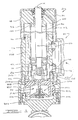
- Shock absorber 10 is a dual tube shock absorber which comprises a piston 12, a piston rod 14, a pressure tube 16, a reserve tube 18, a base valve assembly 20 and a continuously variable servo valve assembly 22.
- Piston 12 is slidingly received within pressure tube 16 and divides pressure tube 16 into an upper working chamber 24 and a lower working chamber 26.
- Piston rod 14 is attached to piston 12 and extends out of pressure tube 16 and reserve tube 18 through a rod guide 34.
- the outer end of piston rod 14 is adapted to be attached to the sprung mass of the vehicle by means known well in the art.
- Reserve tube 18 surrounds pressure tube 16 and with pressure tube 16 defines a reserve chamber 36.
- Reserve tube 18 is adapted for attachment to the unsprung mass of the vehicle by methods known well in the art.
- Base valve assembly 20 is disposed between lower working chamber 26 and reserve chamber 36. Base valve assembly 20 controls the flow of fluid into and out of reserve chamber 36 as described below.
- Continuously variable servo valve assembly 22 comprises an upper intermediate tube 42, a lower intermediate tube 44, a valve interface 46 and a solenoid valve assembly 48.
- Upper intermediate tube 42 is disposed within the upper portion of reserve chamber 36 and sealingly engages rod guide 34.
- Lower intermediate tube 44 is disposed within the lower portion of reserve chamber 36 and sealingly engages base valve assembly 20.
- Valve interface 46 is disposed within reserve chamber 36 and sealingly engages upper intermediate tube 42, lower intermediate tube 44 and pressure tube 16.
- Pressure tube 16, rod guide 34, upper intermediate tube 42 and valve interface 46 define an upper intermediate chamber 50 disposed between reserve chamber 36 and working chambers 24 and 26.
- Pressure tube 16, base valve assembly 20, lower intermediate tube 44 and valve interface 46 define a lower intermediate chamber 52 disposed between reserve chamber 36 and working chambers 24 and 26.
- Valve interface 46 defines a rebound outlet 54 in communication with upper intermediate chamber 50 and a compression outlet 56 in communication with lower intermediate chamber 52.
- Solenoid valve assembly 48 sealingly engages valve interface 46 and is sealingly secured to reserve tube 18.
- Solenoid valve assembly 48 comprises a solenoid coil assembly 58, a solenoid valve body assembly 60 and a spool valve 62.
- Solenoid coil assembly 58 includes a housing 64 within which is contained a set of windings 66 and a coil bobbin 68.
- a valve member 70 is disposed within the set of windings and moves axially within the windings in response to electrical power being supplied to windings 66 as is well known in the art.
- Solenoid coil assembly 58 is attached to solenoid valve body assembly 60.
- Spool valve 62 is disposed within a bore 72 extending through solenoid valve body assembly 60.
- a spring 74 biases spool valve 62 towards solenoid coil assembly 58.
- solenoid coil assembly 58 operates to move spool valve 62 axially within bore 72 of solenoid valve body assembly 60.
- Spool valve 62 is normally in an upper position as shown in Figure 2 and is movable to a lower position as shown in Figure 4 when full power is being supplied to solenoid coil assembly 58.
- the position of spool valve 62 can be intermediate the positions shown in Figures 2 and 4 which is the position shown in Figure 3.
- solenoid valve body assembly 60 comprises a valve body 76, a compression inlet 78, a compression main poppet 80, a compression co-poppet 82, a compression orifice 84, a rebound inlet 88, a rebound main poppet 90, a rebound co-poppet 92 and a rebound orifice 94.
- Solenoid valve assembly 60 is positioned such that valve body 76 sealingly engages valve interface 46 with compression inlet 78 sealingly engaging compression outlet 56 and with rebound inlet 88 sealingly engaging rebound outlet 54.
- a fluid passageway 98 extends between and fluidly connects bore 72 and reserve chamber 36.
- Fluid flow through compression inlet 78 is directed to compression main poppet 80, compression co-poppet 82 and compression orifice 84. Fluid flow through compression main poppet 80 and compression co-poppet 82 is directed back to reserve chamber 36. Fluid flow through compression orifice 84 is directed through spool valve 62 and then returned to reserve chamber 36. Compression main poppet 80 is urged into a closed position by a biasing member 100 and the fluid pressure present at a position between compression orifice 84 and spool valve 62. Fluid pressure from compression inlet 78 urges compression main poppet 80 towards an open position.
- compression co-poppet 82 is urged into a closed position by a biasing member 102 and the fluid pressure present at a position between compression orifice 84 and spool valve 62. Fluid pressure from compression inlet 78 also urges compression co-poppet 82 toward an open position.
- the fluid pressure urging compression main poppet 80 and compression co-poppet 82 towards the open position can be controlled. Fluid flow through rebound inlet 88 is directed to rebound main poppet 90, rebound co-poppet 92 and rebound orifice 94. Fluid flow through rebound main poppet 90 and rebound co-poppet 92 is directed back to reserve chamber 36.
- Fluid flow through rebound orifice 94 is directed through spool valve 62 and then returned to reserve chamber 36.
- Rebound main poppet 90 is urged to a closed position by a biasing member 104 and the fluid pressure present at a position between rebound orifice 94 and spool valve 62. Fluid pressure from rebound inlet 88 urges rebound main poppet 90 towards an open position.
- rebound co-poppet 92 is urged toward a closed position by a biasing member 106 and the fluid pressure present at a position between rebound orifice 94 and spool valve 62. Fluid pressure from rebound inlet 88 also urges rebound co-poppet 92 toward an open position.
- the fluid pressure urging rebound main poppet 90 and rebound co-poppet 92 towards the open position can be controlled.
- base valve assembly 20 of shock absorber 10 comprises a lower mounting adapter 222, a cylinder end 224 and a dual check valve assembly 226.
- Lower mounting adapter 222 is secured to reserve tube 18 and is adapted to be connected to the unsprung mass of the vehicle.
- Cylinder end 224 is secured to lower mounting adapter 222 at one end and lower intermediate tube 44 and valve interface 46 at its opposite end.
- Cylinder end 224 defines a central passage 228 which is in communication with reserve chamber 36 through a passage 230.
- Cylinder end 224 also defines a passage 232 extending between upper intermediate chamber 50 and a chamber 236 located between lower mounting adapter 222 and cylinder end 224 through a bore 238 extending through valve interface 46.
- cylinder end 224 defines a passage 240 extending between chamber 228 and lower working chamber 26 and a passage 242 extending between chamber 228 and chamber 236.
- Dual check valve assembly 226 includes a first one-way check valve 244 and a second one-way check valve 246.
- Check valve 244 allows fluid flow through passage 242 from chamber 228 to chamber 236 but not through passage 242 from chamber 236 to chamber 228.
- Check valve 246 allows fluid flow through passage 240 between chamber 228 and lower working chamber 26 but not through passage 240 from lower working chamber 26 to chamber 228.
- shock absorber 10 there is no damping force characteristic in either rebound or compression that is determined by piston 12.
- the damping force characteristics for shock absorber 10 are controllable by continuously variable servo valve assembly 22 such that in any given complete stroke of shock absorber 10 (rebound to compression to rebound) depending on the amount of current given to energize solenoid coil assembly 58. With little or no current is given to energize solenoid coil assembly 58, continuously variable servo valve assembly 22 generates a firm rebound damping force with a soft compression damping force for shock absorber 10. When full current to solenoid coil assembly 58 is supplied, continuously variable servo valve assembly 22 generates a soft rebound damping force with a firm compression damping force for shock absorber 10.
- continuously variable servo valve assembly 22 Another characteristic of continuously variable servo valve assembly 22 is that when a continuously variable energy signal (through pulse width modulation) is provided to solenoid coil assembly 58, a continuously variable sloping bleed and a continuously variable level blowoff for poppets 80, 82, 90 and 92 are provided. The basis for this characteristic is shown in Figure 6.
- Figure 6 discloses schematically compression main poppet 80. While Figure 6 is directed to compression main poppet 80, it is to be understood that compression co-poppet 82, rebound main poppet 90 and rebound co-poppet 92 operate in a similar manner to main poppet 80.
- Compression main poppet 80 includes a valve member 110 disposed within a bore 112 in valve body 76 of solenoid valve body assembly 60.
- a spring 114 urges valve member 110 into a closed position as shown in Figure 6.
- Fluid flow from compression inlet 78 is directed to a fluid inlet 116, through an internal bore 124 in valve member 110, and then to compression orifice 84. From compression orifice 84, fluid flows back to reserve chamber 36 through a passage 120.
- a blowoff passage 122 extends from bore 112 to passage 120 to allow fluid flow when valve member 110 is moved to an open position.
- the amount of fluid flow allowed through compression orifice 84 and rebound orifice 94 will be determined by the position of spool valve 62 as shown in Figures 2-4.
- passage 120 adjacent rebound inlet 88 returns fluid from passage 120 of rebound poppets 90 and 92 as well as from rebound orifice 94.
- Passage 120 shown adjacent compression inlet 78 returns fluid from passage 120 of compression poppets 80 and 82 as well as from compression orifice 84.
- Figure 2 shows spool valve 62 positioned to fully open compression orifice 84 and fully close rebound orifice 94.
- Fluid is free to flow through compression orifice 84, through a bore 124 extending through spool valve 62, through passageway 98 and back to reserve chamber 36 to provide soft compression damping. Fluid is prohibited from flowing through rebound orifice 94 thus providing firm compression damping.
- Figure 3 shows spool valve 62 positioned to open both compression orifice 84 and rebound orifice 94. Thus a soft compression damping force and a soft rebound damping force are provided. Fluid is free to flow through both compression orifice 84 and rebound orifice 94 to reserve chamber 36 as described above to provide soft compression and rebound damping.
- Figure 4 shows spool valve 62 positioned to fully close compression orifice 84 and fully open rebound orifice 94.
- a firm compression damping force and a soft rebound damping force are provided. Fluid is prohibited from flowing through compression orifice 84 to provide firm compression damping. Fluid is free to flow through rebound orifice 94 to reserve chamber 36 as described above to provide soft rebound damping.
- the amount of firm and/or soft damping provided will be determined by the position of spool valve 62 which in turn is determined by the amount of current being supplied to solenoid coil assembly 58. Preferably, the amount of current to solenoid coil assembly 58 is controlled using pulse width modulation.
- fluid is forced through a passage 130 formed in rod guide 34.
- the fluid enters upper intermediate chamber 50 which is concentric with working chambers 24 and 26.
- a first portion of the fluid exits through rebound outlet 54 and enters rebound inlet 88 of continuously variable servo valve assembly 22 opening one-way check valve 96.
- rebound main poppet 90 After entering rebound inlet 88, fluid flows to rebound main poppet 90, rebound co-poppet 92 and to rebound orifice 94.
- the amount of flow through rebound orifice 94 is controlled by the position of spool valve 62 to control the damping characteristics from a firm ride to a soft ride. Fluid flowing through continuously variable servo valve assembly 22 is directed to reserve chamber 36.
- a first portion of fluid flow is forced through a passage 132 formed in base valve assembly 20.
- the fluid enters lower intermediate chamber 52 which is concentric with working chambers 24 and 26. Fluid exits through compression outlet 56 and enters compression inlet 78 of continuously variable servo valve assembly 22. After entering compression inlet 78, fluid flows to compression main poppet 80, compression co-poppet 82 and to compression orifice 84. As described above, the amount of flow through compression orifice 84 is controlled by the position of spool valve 62 to control the damping characteristics from a soft ride to a firm ride. Fluid flowing through continuously variable servo valve assembly 22 is directed to reserve chamber 36.
- check valve 246 Because the pressure in lower working chamber 26 is greater than the pressure in reserve chamber 36, check valve 246 remains closed. The compression movement of piston 12 creates a low pressure within upper working chamber 24 that is lower than the pressure within reserve chamber 36. Thus, check valve 244 opens to allow fluid flow from reserve chamber 36 through passage 230 and into chamber 228. From chamber 228, fluid flows through passage 242 and check valve 244, into chamber 236, through passage 232, through bore 238, through passage 130 and into upper working chamber 24.
- shock absorber 10 thus provides an infinitely variable solenoid actuated continuously variable shock absorber. Some, but not all of the advantages of this contraction are given below.
- shock absorber 10 provides a greater differentiation from soft to firm damping forces in compression due to the introduction of separate compression flow passages and check valves.
- shock absorber 10 provides for a separately tunable rebound and compression valving.
- shock absorber 10 provides soft compression damping forces and firm rebound damping forces during the same stroke. Conversely, firm compression damping forces and soft rebound damping forces during the same stroke are also available.
- shock absorber 10 nullifies the need for a piston valving system.
- shock absorber 10 allows for continuously variable bleed and blowoff features.
- Sixth, continuously variable servo valve assembly 22 differentiates between compression strokes and rebound strokes.
Landscapes
- Engineering & Computer Science (AREA)
- General Engineering & Computer Science (AREA)
- Mechanical Engineering (AREA)
- Physics & Mathematics (AREA)
- Electromagnetism (AREA)
- Fluid-Damping Devices (AREA)
- Vehicle Body Suspensions (AREA)
Applications Claiming Priority (2)
| Application Number | Priority Date | Filing Date | Title |
|---|---|---|---|
| US624682 | 2000-07-24 | ||
| US09/624,682 US6464048B1 (en) | 2000-07-24 | 2000-07-24 | Solenoid actuated continuously variable shock absorber |
Publications (3)
| Publication Number | Publication Date |
|---|---|
| EP1176334A2 true EP1176334A2 (fr) | 2002-01-30 |
| EP1176334A3 EP1176334A3 (fr) | 2004-01-07 |
| EP1176334B1 EP1176334B1 (fr) | 2008-03-19 |
Family
ID=24502910
Family Applications (1)
| Application Number | Title | Priority Date | Filing Date |
|---|---|---|---|
| EP01117501A Expired - Lifetime EP1176334B1 (fr) | 2000-07-24 | 2001-07-20 | Amortisseur à variation continue actionné par un soleinoide |
Country Status (4)
| Country | Link |
|---|---|
| US (1) | US6464048B1 (fr) |
| EP (1) | EP1176334B1 (fr) |
| BR (1) | BR0103017A (fr) |
| DE (1) | DE60133246T2 (fr) |
Cited By (4)
| Publication number | Priority date | Publication date | Assignee | Title |
|---|---|---|---|---|
| DE10260394B3 (de) * | 2002-12-21 | 2004-06-09 | Zf Sachs Ag | Schwingungsdämpfer mit verstellbarer Dämpfkraft |
| DE10260395B3 (de) * | 2002-12-21 | 2004-06-09 | Zf Sachs Ag | Schwingungsdämpfer mit verstellbarer Dämpfkraft |
| DE112004002411B4 (de) * | 2003-12-08 | 2016-01-21 | Tenneco Automotive Operating Company Inc. | Magnetisch betätigtes, stufenlos einstellbares Servoventil zur Anpassung der Dämpfung bei Stoßdämpfern und Federbeinen |
| CN110921458A (zh) * | 2019-12-16 | 2020-03-27 | 泗县金皖泵业有限公司 | 一种点刹式液压缓冲器 |
Families Citing this family (17)
| Publication number | Priority date | Publication date | Assignee | Title |
|---|---|---|---|---|
| CA2350624A1 (fr) * | 1998-11-11 | 2000-05-18 | Kenmar Company Trust | Systeme adaptatif de suspension optimise par ordinateur et methode correspondante |
| US6964325B2 (en) * | 2003-09-15 | 2005-11-15 | Tenneco Automotive Operating Company Inc. | Integrated tagging system for an electronic shock absorber |
| US6978871B2 (en) * | 2003-09-17 | 2005-12-27 | Tenneco Automotive Operating Company Inc. | Adjustable damper with control valve, mounted in an external collar |
| JP2006064098A (ja) * | 2004-08-27 | 2006-03-09 | Kayaba Ind Co Ltd | フロントフォーク |
| DE102005048949B3 (de) * | 2005-10-13 | 2006-12-14 | Zf Friedrichshafen Ag | Schwingungsdämpfer mit verstellbarer Dämpfkraft |
| US20070278028A1 (en) * | 2006-06-05 | 2007-12-06 | Wayne Robert Fought | Anti-aeration system for a suspension actuator |
| US7950506B2 (en) * | 2007-07-31 | 2011-05-31 | Tenneco Automotive Operating Company Inc. | Semi third tube design |
| US9285011B2 (en) * | 2008-09-26 | 2016-03-15 | Tenneco Automotive Operating Company Inc. | High velocity compression damping valve |
| US9062737B2 (en) | 2012-06-04 | 2015-06-23 | Mclaren Automotive Limited | Shock absorber with four chambers |
| GB201303400D0 (en) | 2013-02-26 | 2013-04-10 | Mclaren Automotive Ltd | Damper unit |
| JP6697485B2 (ja) * | 2015-05-29 | 2020-05-20 | 日立オートモティブシステムズ株式会社 | 振動減衰装置 |
| IT201800007584A1 (it) * | 2018-07-27 | 2020-01-27 | Sistemi Sospensioni Spa | Ammortizzatore idraulico a smorzamento variabile, particolarmente per sospensione di veicolo. |
| DE102019212908B4 (de) * | 2019-08-28 | 2024-10-17 | Thyssenkrupp Ag | Schwingungsdämpfer mit verstellbarer Dämpfkraft |
| US20220234679A1 (en) * | 2021-01-28 | 2022-07-28 | Fox Factory, Inc. | Damper with an annular base valve flow system |
| US12454991B2 (en) | 2022-01-13 | 2025-10-28 | Advanced Suspension Technology Llc | Space saving pressure relief valves for suspension dampers |
| DE102022209324A1 (de) * | 2022-09-07 | 2024-03-07 | Thyssenkrupp Ag | Schwingungsdämpfer |
| US20240309932A1 (en) * | 2023-01-24 | 2024-09-19 | Fox Factory, Inc. | Live valve poppet |
Family Cites Families (18)
| Publication number | Priority date | Publication date | Assignee | Title |
|---|---|---|---|---|
| US3638885A (en) * | 1970-03-09 | 1972-02-01 | Boeing Co | Lag frequency selective damper |
| US3757910A (en) | 1971-07-29 | 1973-09-11 | Monroe Auto Equipment Co | Shock absorber and compression valve assembly |
| US4084668A (en) * | 1975-06-05 | 1978-04-18 | United Technologies Corporation | Redundant damper seals |
| CA1058643A (fr) | 1976-03-22 | 1979-07-17 | Dale A. Palmer | Amortisseur |
| DE3524863A1 (de) * | 1985-04-12 | 1986-10-30 | Robert Bosch Gmbh, 7000 Stuttgart | Verfahren und vorrichtung zum steuern der federhaerte, insbesondere bei fahrzeugen |
| JPH0725251B2 (ja) | 1987-01-16 | 1995-03-22 | 本田技研工業株式会社 | 関連サスペンシヨン装置 |
| AT391801B (de) * | 1987-10-30 | 1990-12-10 | Bock Orthopaed Ind | Hydraulische steuerung |
| US4854429A (en) | 1987-12-18 | 1989-08-08 | Casey Gary L | Variable rate shock absorber and system therefor |
| DE3803888A1 (de) * | 1988-02-09 | 1989-08-17 | Boge Ag | Regelbarer schwingungsdaempfer |
| US4890858A (en) | 1988-02-16 | 1990-01-02 | Monroe Auto Equipment Company | Method and apparatus for controlling shock absorbers |
| DE4041619A1 (de) | 1990-12-22 | 1992-06-25 | Bosch Gmbh Robert | Zylinder |
| DE4132262A1 (de) * | 1991-09-27 | 1993-04-01 | Teves Gmbh Alfred | Hydraulischer regelbarer schwingungsdaempfer fuer kraftfahrzeuge |
| US5586627A (en) | 1993-05-20 | 1996-12-24 | Tokico, Ltd. | Hydraulic shock absorber of damping force adjustable type |
| US5655633A (en) | 1994-05-20 | 1997-08-12 | Tokico Ltd. | Hydraulic damper of a damping force adjusting type |
| JPH08184344A (ja) * | 1994-12-29 | 1996-07-16 | Tokico Ltd | 減衰力調整式油圧緩衝器 |
| US5588510A (en) | 1995-09-25 | 1996-12-31 | Husco International, Inc. | Variable damping force shock absorber |
| JPH09264364A (ja) * | 1996-01-25 | 1997-10-07 | Tokico Ltd | 油圧緩衝器 |
| JP3829264B2 (ja) * | 1996-03-19 | 2006-10-04 | 株式会社日立製作所 | 減衰力調整式油圧緩衝器 |
-
2000
- 2000-07-24 US US09/624,682 patent/US6464048B1/en not_active Expired - Fee Related
-
2001
- 2001-07-20 EP EP01117501A patent/EP1176334B1/fr not_active Expired - Lifetime
- 2001-07-20 DE DE60133246T patent/DE60133246T2/de not_active Expired - Fee Related
- 2001-07-24 BR BR0103017-5A patent/BR0103017A/pt active Search and Examination
Non-Patent Citations (1)
| Title |
|---|
| None |
Cited By (5)
| Publication number | Priority date | Publication date | Assignee | Title |
|---|---|---|---|---|
| DE10260394B3 (de) * | 2002-12-21 | 2004-06-09 | Zf Sachs Ag | Schwingungsdämpfer mit verstellbarer Dämpfkraft |
| DE10260395B3 (de) * | 2002-12-21 | 2004-06-09 | Zf Sachs Ag | Schwingungsdämpfer mit verstellbarer Dämpfkraft |
| US7017719B2 (en) | 2002-12-21 | 2006-03-28 | Zf Sachs Ag | Vibration damper with adjustable damping force |
| DE112004002411B4 (de) * | 2003-12-08 | 2016-01-21 | Tenneco Automotive Operating Company Inc. | Magnetisch betätigtes, stufenlos einstellbares Servoventil zur Anpassung der Dämpfung bei Stoßdämpfern und Federbeinen |
| CN110921458A (zh) * | 2019-12-16 | 2020-03-27 | 泗县金皖泵业有限公司 | 一种点刹式液压缓冲器 |
Also Published As
| Publication number | Publication date |
|---|---|
| DE60133246T2 (de) | 2009-05-14 |
| DE60133246D1 (de) | 2008-04-30 |
| EP1176334B1 (fr) | 2008-03-19 |
| US6464048B1 (en) | 2002-10-15 |
| EP1176334A3 (fr) | 2004-01-07 |
| BR0103017A (pt) | 2002-02-26 |
Similar Documents
| Publication | Publication Date | Title |
|---|---|---|
| US7438164B2 (en) | Solenoid actuated continuously variable servo valve for adjusting damping in shock absorbers and struts | |
| US6464048B1 (en) | Solenoid actuated continuously variable shock absorber | |
| US5934422A (en) | Step motor actuated continuously variable shock absorber | |
| US8511444B2 (en) | Shock absorber having a continuously variable valve with base line valving | |
| KR100204943B1 (ko) | 감쇠력 조정식 유압 완충기 | |
| US5503258A (en) | Hydraulic shock absorber | |
| EP1975453B1 (fr) | Amortisseur de chocs à pression fluide réglable | |
| KR101326935B1 (ko) | 감쇠력 조정식 유압 완충기 | |
| US5096025A (en) | Two-way magnetic valve with bypass control | |
| US7654369B2 (en) | Hydraulic vibration damper piston with an integral electrically operated adjustment valve | |
| EP1983213B1 (fr) | Absorbeur de chocs à pression fluide réglable de force d'amortissement | |
| US5588510A (en) | Variable damping force shock absorber | |
| US20020000352A1 (en) | Damping force control type hydraulic shock absorber | |
| US5911290A (en) | Step motor actuated continuous variable shock absorber | |
| EP0477326B1 (fr) | Ensemble amortisseur reglable | |
| JP2003166585A (ja) | 減衰力調整式油圧緩衝器 | |
| US5400877A (en) | Two-tube shock absorber | |
| JP4096153B2 (ja) | 減衰力調整式油圧緩衝器 | |
| US6793048B1 (en) | Solenoid actuated continuously variable shock absorber | |
| JPH109327A (ja) | 減衰力調整式油圧緩衝器 | |
| JP3265523B2 (ja) | 減衰力調整式油圧緩衝器 | |
| GB2378231A (en) | A damper for a vehicle suspension with externally mounted semi-active system | |
| US20030173167A1 (en) | Shock absorber |
Legal Events
| Date | Code | Title | Description |
|---|---|---|---|
| PUAI | Public reference made under article 153(3) epc to a published international application that has entered the european phase |
Free format text: ORIGINAL CODE: 0009012 |
|
| AK | Designated contracting states |
Kind code of ref document: A2 Designated state(s): AT BE CH CY DE DK ES FI FR GB GR IE IT LI LU MC NL PT SE TR |
|
| AX | Request for extension of the european patent |
Free format text: AL;LT;LV;MK;RO;SI |
|
| PUAL | Search report despatched |
Free format text: ORIGINAL CODE: 0009013 |
|
| AK | Designated contracting states |
Kind code of ref document: A3 Designated state(s): AT BE CH CY DE DK ES FI FR GB GR IE IT LI LU MC NL PT SE TR |
|
| AX | Request for extension of the european patent |
Extension state: AL LT LV MK RO SI |
|
| 17P | Request for examination filed |
Effective date: 20040211 |
|
| 17Q | First examination report despatched |
Effective date: 20040414 |
|
| AKX | Designation fees paid |
Designated state(s): DE FR GB |
|
| GRAP | Despatch of communication of intention to grant a patent |
Free format text: ORIGINAL CODE: EPIDOSNIGR1 |
|
| GRAS | Grant fee paid |
Free format text: ORIGINAL CODE: EPIDOSNIGR3 |
|
| GRAA | (expected) grant |
Free format text: ORIGINAL CODE: 0009210 |
|
| AK | Designated contracting states |
Kind code of ref document: B1 Designated state(s): DE FR GB |
|
| REG | Reference to a national code |
Ref country code: GB Ref legal event code: FG4D |
|
| REF | Corresponds to: |
Ref document number: 60133246 Country of ref document: DE Date of ref document: 20080430 Kind code of ref document: P |
|
| ET | Fr: translation filed | ||
| PLBE | No opposition filed within time limit |
Free format text: ORIGINAL CODE: 0009261 |
|
| STAA | Information on the status of an ep patent application or granted ep patent |
Free format text: STATUS: NO OPPOSITION FILED WITHIN TIME LIMIT |
|
| 26N | No opposition filed |
Effective date: 20081222 |
|
| PGFP | Annual fee paid to national office [announced via postgrant information from national office to epo] |
Ref country code: FR Payment date: 20090716 Year of fee payment: 9 |
|
| PGFP | Annual fee paid to national office [announced via postgrant information from national office to epo] |
Ref country code: DE Payment date: 20090722 Year of fee payment: 9 Ref country code: GB Payment date: 20090720 Year of fee payment: 9 |
|
| GBPC | Gb: european patent ceased through non-payment of renewal fee |
Effective date: 20100720 |
|
| REG | Reference to a national code |
Ref country code: FR Ref legal event code: ST Effective date: 20110331 |
|
| PG25 | Lapsed in a contracting state [announced via postgrant information from national office to epo] |
Ref country code: DE Free format text: LAPSE BECAUSE OF NON-PAYMENT OF DUE FEES Effective date: 20110201 |
|
| REG | Reference to a national code |
Ref country code: DE Ref legal event code: R119 Ref document number: 60133246 Country of ref document: DE Effective date: 20110201 |
|
| PG25 | Lapsed in a contracting state [announced via postgrant information from national office to epo] |
Ref country code: FR Free format text: LAPSE BECAUSE OF NON-PAYMENT OF DUE FEES Effective date: 20100802 |
|
| PG25 | Lapsed in a contracting state [announced via postgrant information from national office to epo] |
Ref country code: GB Free format text: LAPSE BECAUSE OF NON-PAYMENT OF DUE FEES Effective date: 20100720 |