EP1176349A2 - Vorrichtung zum Verankern von Rohren und Kanaelen - Google Patents
Vorrichtung zum Verankern von Rohren und Kanaelen Download PDFInfo
- Publication number
- EP1176349A2 EP1176349A2 EP01116910A EP01116910A EP1176349A2 EP 1176349 A2 EP1176349 A2 EP 1176349A2 EP 01116910 A EP01116910 A EP 01116910A EP 01116910 A EP01116910 A EP 01116910A EP 1176349 A2 EP1176349 A2 EP 1176349A2
- Authority
- EP
- European Patent Office
- Prior art keywords
- collar
- ducts
- anchoring
- pipes
- anchoring device
- Prior art date
- Legal status (The legal status is an assumption and is not a legal conclusion. Google has not performed a legal analysis and makes no representation as to the accuracy of the status listed.)
- Granted
Links
- 238000004873 anchoring Methods 0.000 title claims abstract description 47
- 239000000463 material Substances 0.000 claims abstract description 6
- 239000002184 metal Substances 0.000 claims abstract description 6
- 229920003023 plastic Polymers 0.000 claims abstract description 5
- 239000004033 plastic Substances 0.000 claims abstract description 5
- 238000010276 construction Methods 0.000 claims description 5
- 238000005452 bending Methods 0.000 claims description 4
- 238000000465 moulding Methods 0.000 claims 1
- 230000003068 static effect Effects 0.000 description 3
- 238000013459 approach Methods 0.000 description 1
- 230000008878 coupling Effects 0.000 description 1
- 238000010168 coupling process Methods 0.000 description 1
- 238000005859 coupling reaction Methods 0.000 description 1
- 238000003754 machining Methods 0.000 description 1
- 238000012986 modification Methods 0.000 description 1
- 230000004048 modification Effects 0.000 description 1
Images



Classifications
-
- F—MECHANICAL ENGINEERING; LIGHTING; HEATING; WEAPONS; BLASTING
- F16—ENGINEERING ELEMENTS AND UNITS; GENERAL MEASURES FOR PRODUCING AND MAINTAINING EFFECTIVE FUNCTIONING OF MACHINES OR INSTALLATIONS; THERMAL INSULATION IN GENERAL
- F16L—PIPES; JOINTS OR FITTINGS FOR PIPES; SUPPORTS FOR PIPES, CABLES OR PROTECTIVE TUBING; MEANS FOR THERMAL INSULATION IN GENERAL
- F16L3/00—Supports for pipes, cables or protective tubing, e.g. hangers, holders, clamps, cleats, clips, brackets
- F16L3/08—Supports for pipes, cables or protective tubing, e.g. hangers, holders, clamps, cleats, clips, brackets substantially surrounding the pipe, cable or protective tubing
- F16L3/10—Supports for pipes, cables or protective tubing, e.g. hangers, holders, clamps, cleats, clips, brackets substantially surrounding the pipe, cable or protective tubing divided, i.e. with two members engaging the pipe, cable or protective tubing
- F16L3/1008—Supports for pipes, cables or protective tubing, e.g. hangers, holders, clamps, cleats, clips, brackets substantially surrounding the pipe, cable or protective tubing divided, i.e. with two members engaging the pipe, cable or protective tubing with two members engaging the pipe, cable or tubing, both being made of thin band material completely surrounding the pipe
Definitions
- the present invention relates to an improved device for anchoring pipes and/or ducts in general.
- the device comprises, in particular, a quick clamping collar, specifically designed for optimizing the pipe or duct locking stability as well as the assembling time of said pipes or ducts in civil and industrial systems.
- Prior devices for clamping pipes and ducts conventionally comprise metal bands or clamps, including two annular discrete circular sectors, defining an open annular body, called "collar”.
- One of the above mentioned collar sectors provides a seat for housing therein the pipe or duct.
- Said seat providing sector comprises, on a rear portion thereof, an element for allowing said sector to be clamped to a masonry construction, providing a firm binding region of the system.
- the second circular sector is brought to an adjoining relationship with the first sector, thereby holding therebetween the pipe cylindric body, engaged in the annular hollow defined by the two collar sectors.
- Both said collar sectors are provided, at their end portions, with flat and elongated parts, conventionally called “fins”, which outward radially extend and are provided, at their central region, with a respective throughgoing hole.
- Said fins are arranged in a mutual facing relationship, and the throughgoing holes formed therein allows said fins to be mutually coupled by a screw type of clamping element.
- the anchoring time of said pipe is very long.
- the operator must perform a plurality of very different operations, comprising the unscrewing of the two screws, freeing the fist collar sector while simultaneously opening the collar, locating the pipe in the available seat therefor, overlapping again the second collar sector on the first, performing a first loose clamping of one of the two clamping screws, providing the same clamping on the other screw, and continuing to alternately clamping both the screws up to the end or limit positions thereof.
- the aim of the present invention is to provide civil and industrial system assembling operators with an improved anchoring device for anchoring pipes and/or ducts in general, which includes a quick clamping collar specifically designed for optimizing and facilitating the pipe anchoring operations, while greatly reducing the assembling time.
- a main object of the present invention is to provide a firm anchoring of the pipes to the element constituting the static binding region.
- a further object of the present invention is to simplify and reduce the cost of the anchoring device, by requiring a single mold to make the two like half-collars, instead of providing two molds as in the case of the conventional two half collars.
- Yet another object of the present invention is to speed up and facilitate the operations for assembling the system pipes and/or ducts.
- an improved anchoring device for anchoring pipes and/or ducts in general, characterized in that said anchoring device comprises a bottom half-collar and a top half-collar, said bottom and half-collars being identical to one another and made of a metal or plastics material, and having end portions provided with two prismatic fins, extending the semicircular construction of each half collar and including, on a side thereof, rectangular cross-section grooves, so made as to form housing seats which, as said half-collars are brought to an opposite adjoining relationship, firmly engage one another and by a screw arranged at one end of a half-collar which screw, as it is screwed on, simultaneously locks said two half-collars and pipe.
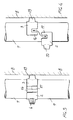
- an anchoring device for anchoring pipes and ducts in general, including a collar specifically designed for optimizing the locking of said pipes, while reducing their assembling times in civil and industrial systems, said device being illustrated, by way of an indicative, but not limitative, example in the figures of the accompanying drawings, where:
- the improved anchoring device for anchoring pipes and/or ducts in general comprises a top half-collar 2 and a like bottom half-collar 3, said half-collars being preferably made of a metal or plastics material.
- the anchoring device further comprises a plug 4 and a screw 5 for anchoring said device to a static binding element 8, said plug and screw being housed in a perforated recess 9.
- the anchoring device comprises moreover a screw clamping element 6, engaged in said recess 10, which can have a shape either equal or different to the shape of the perforated recess 9 assuring the locking of the pipe or duct.
- the half-collar as molded, will assume a given bending radius, which is incrementally changed at the two end portions thereof, where said half-collar is provided with the two fins 11 and 12, by linearizing two first lengths 21 and 22 operating as a fitting elements between the two bending radii A and B.
- the radial variation is equal to or greater than the thickness of the sheet element and that it allows the fins to be abutted one against the other as the seats or recesses 13 and 14 are overlapped on the linearized lengths 21 and 22 of the opposite half-collar.
- the tongue elements 17 and 18 are like the tongue elements 15 and 16 of the half-collar 3.
- the recesses 9 and 10 are arranged at the top of the respective half-collar and outward project by a frustum of cone shaped body 19 and 20 having any suitable length and diameter and thread.
- the above mentioned frustum of cone shaped bodies can be replaced by other bodies provided with outer threads and fixed to the half-collars.
- Said bodies are provided with respective inner threads, having any suitable thread pitch.
- the tongue elements 15 and 16 are beveled at their corners, with a suitable beveling angle, which beveled arrangement is also provided at the inlet corners of the grooves or seats 13 and 14.
- the operator will lock it by a single movement from the bottom to the top or vice-versa, depending on the position of the half-collar 3, in this operation the seats or recesses 13 and 14 overlapping on the linear lengths 21, 22 of the half-collar 2.
- the operator will actuated the clamping screws 6 for engaging it with the thread of the recess 10 and, by urging the pipe, the operator will put under tension the half-collar 2 with respect to the half-collar 3 by providing, in the abutment between the tongue elements 16 and 17 and 15 and 18, an effort or force clamping the collar to the pipe 7.
- an anchoring device which is very practical and functional, allowing to simply and quickly anchoring or locking pipes and ducts, while providing a very firm connection of the end portions of two like half-collars, and a perfect clamping, by operating a single clamping screw arranged at a central position with respect to the anchoring device and pipe to be locked.
- the used materials, as well as the contingent size and shapes can be any, depending on requirements.
Landscapes
- Engineering & Computer Science (AREA)
- General Engineering & Computer Science (AREA)
- Mechanical Engineering (AREA)
- Devices Affording Protection Of Roads Or Walls For Sound Insulation (AREA)
- Supports For Pipes And Cables (AREA)
- Joining Of Building Structures In Genera (AREA)
- Electric Cable Installation (AREA)
- Reciprocating Pumps (AREA)
- Pipe Accessories (AREA)
- Piles And Underground Anchors (AREA)
- Wire Processing (AREA)
Applications Claiming Priority (2)
| Application Number | Priority Date | Filing Date | Title |
|---|---|---|---|
| IT2000MI000443U IT250169Y1 (it) | 2000-07-26 | 2000-07-26 | Dispositivo per l'ancoraggio di tubi e di condotte in genere |
| ITMI000443U | 2000-07-26 |
Publications (3)
| Publication Number | Publication Date |
|---|---|
| EP1176349A2 true EP1176349A2 (de) | 2002-01-30 |
| EP1176349A3 EP1176349A3 (de) | 2003-05-28 |
| EP1176349B1 EP1176349B1 (de) | 2005-02-02 |
Family
ID=11444346
Family Applications (1)
| Application Number | Title | Priority Date | Filing Date |
|---|---|---|---|
| EP01116910A Expired - Lifetime EP1176349B1 (de) | 2000-07-26 | 2001-07-11 | Vorrichtung zum Verankern von Rohren und Kanaelen |
Country Status (6)
| Country | Link |
|---|---|
| EP (1) | EP1176349B1 (de) |
| AT (1) | ATE288554T1 (de) |
| DE (1) | DE60108687T2 (de) |
| ES (1) | ES2238037T3 (de) |
| IT (1) | IT250169Y1 (de) |
| PT (1) | PT1176349E (de) |
Cited By (4)
| Publication number | Priority date | Publication date | Assignee | Title |
|---|---|---|---|---|
| EP1510704A1 (de) * | 2003-08-29 | 2005-03-02 | KUKA Roboter GmbH | Befestigungsvorrichtung |
| EP1544527A1 (de) * | 2003-12-17 | 2005-06-22 | Raccorderie Metalliche S.p.A. | Rohrschelle zur Wandbefestigung von Leitungen |
| US20180363805A1 (en) * | 2017-06-20 | 2018-12-20 | Paccar Inc | Interlocking pipe support |
| JP2020180653A (ja) * | 2019-04-25 | 2020-11-05 | 日栄インテック株式会社 | 配管支持具 |
Families Citing this family (1)
| Publication number | Priority date | Publication date | Assignee | Title |
|---|---|---|---|---|
| US10598302B2 (en) | 2017-12-27 | 2020-03-24 | TorcSill Foundations, LLC | Safety anchor device for high pressure pipe couplings |
Family Cites Families (4)
| Publication number | Priority date | Publication date | Assignee | Title |
|---|---|---|---|---|
| GB177271A (en) * | 1920-12-29 | 1922-03-29 | Evered & Compy Ltd | Improvements in and in the manufacture of adjustable sockets for the brackets of shop window and other like fittings |
| FR530158A (fr) * | 1921-01-25 | 1921-12-17 | Collier de soutien | |
| DE2138782B1 (de) * | 1971-08-03 | 1972-12-21 | Grieshaber Gmbh Draht U Stahlverarbeitung | Verbindungsteil |
| NL8803130A (nl) * | 1988-12-21 | 1990-07-16 | Wit J H En Zonen De | Bevestigingsinrichting voor pijpen. |
-
2000
- 2000-07-26 IT IT2000MI000443U patent/IT250169Y1/it active
-
2001
- 2001-07-11 AT AT01116910T patent/ATE288554T1/de not_active IP Right Cessation
- 2001-07-11 EP EP01116910A patent/EP1176349B1/de not_active Expired - Lifetime
- 2001-07-11 ES ES01116910T patent/ES2238037T3/es not_active Expired - Lifetime
- 2001-07-11 PT PT01116910T patent/PT1176349E/pt unknown
- 2001-07-11 DE DE60108687T patent/DE60108687T2/de not_active Expired - Lifetime
Non-Patent Citations (1)
| Title |
|---|
| None |
Cited By (6)
| Publication number | Priority date | Publication date | Assignee | Title |
|---|---|---|---|---|
| EP1510704A1 (de) * | 2003-08-29 | 2005-03-02 | KUKA Roboter GmbH | Befestigungsvorrichtung |
| EP1544527A1 (de) * | 2003-12-17 | 2005-06-22 | Raccorderie Metalliche S.p.A. | Rohrschelle zur Wandbefestigung von Leitungen |
| US20180363805A1 (en) * | 2017-06-20 | 2018-12-20 | Paccar Inc | Interlocking pipe support |
| US10753514B2 (en) * | 2017-06-20 | 2020-08-25 | Paccar Inc | Interlocking pipe support |
| JP2020180653A (ja) * | 2019-04-25 | 2020-11-05 | 日栄インテック株式会社 | 配管支持具 |
| JP7287827B2 (ja) | 2019-04-25 | 2023-06-06 | 日栄インテック株式会社 | 配管支持具 |
Also Published As
| Publication number | Publication date |
|---|---|
| DE60108687T2 (de) | 2006-03-16 |
| DE60108687D1 (de) | 2005-03-10 |
| ES2238037T3 (es) | 2005-08-16 |
| IT250169Y1 (it) | 2003-07-24 |
| EP1176349A3 (de) | 2003-05-28 |
| EP1176349B1 (de) | 2005-02-02 |
| ITMI20000443V0 (it) | 2000-07-26 |
| PT1176349E (pt) | 2005-06-30 |
| ITMI20000443U1 (it) | 2002-01-26 |
| ATE288554T1 (de) | 2005-02-15 |
Similar Documents
| Publication | Publication Date | Title |
|---|---|---|
| US4298330A (en) | Curved mandrel for curing polymeric hose and method | |
| US11668416B2 (en) | Gland assembly | |
| CA2627332C (en) | Coupling having angularly oriented cavity | |
| US4135961A (en) | Method of molding a socket part on a synthetic resinous pipe end | |
| JP2002531734A (ja) | 中空プロフィールロッド | |
| KR20120093836A (ko) | 나사식 관 이음 및 나사식 관 이음 제조 방법 | |
| US6267417B1 (en) | Angle setting pipe structure and its fabrication method | |
| US4258936A (en) | Coupling | |
| EP1176349B1 (de) | Vorrichtung zum Verankern von Rohren und Kanaelen | |
| US6406067B1 (en) | Lateral pipe adaptor | |
| US7143991B2 (en) | Reinforcing bar joint sleeve fixing device | |
| KR102184827B1 (ko) | 벽체용 관통슬리브 | |
| US20030218304A1 (en) | Boot connector designed to be cast in radial progression and method and apparatus for its production and use | |
| US4547004A (en) | Coupling | |
| US3401957A (en) | Split t | |
| JPH0781656B2 (ja) | 管継手密封装置 | |
| JP2024003274A (ja) | コンクリート部材の連結装置 | |
| JP3641017B2 (ja) | 連結装置及び継手金具 | |
| CN1039890A (zh) | 快速作用的流体管道联接器 | |
| US4667500A (en) | Flaring device for pipe ends | |
| JP7221084B2 (ja) | 樹脂成形体、その製造方法及びシース接続口成形用挿入具 | |
| JP6751694B2 (ja) | シース接続口成形用挿入具、シース接続口の成形方法及びコンクリートセグメントの設置方法 | |
| JPH0633278Y2 (ja) | 管継手用スリーブ | |
| US20060157979A1 (en) | Coupling member for use in a system with flowing fluid comprising integral locking tonques for engaging wing .e.g. an annular groove | |
| JP7679082B2 (ja) | 鋼管と継手の接続機構 |
Legal Events
| Date | Code | Title | Description |
|---|---|---|---|
| PUAI | Public reference made under article 153(3) epc to a published international application that has entered the european phase |
Free format text: ORIGINAL CODE: 0009012 |
|
| AK | Designated contracting states |
Kind code of ref document: A2 Designated state(s): AT BE CH CY DE DK ES FI FR GB GR IE IT LI LU MC NL PT SE TR |
|
| AX | Request for extension of the european patent |
Free format text: AL;LT;LV;MK;RO;SI |
|
| PUAL | Search report despatched |
Free format text: ORIGINAL CODE: 0009013 |
|
| AK | Designated contracting states |
Designated state(s): AT BE CH CY DE DK ES FI FR GB GR IE IT LI LU MC NL PT SE TR |
|
| AX | Request for extension of the european patent |
Extension state: AL LT LV MK RO SI |
|
| RIC1 | Information provided on ipc code assigned before grant |
Ipc: 7F 16L 3/04 A Ipc: 7F 16L 3/10 B |
|
| 17P | Request for examination filed |
Effective date: 20031113 |
|
| AKX | Designation fees paid |
Designated state(s): AT BE CH CY DE DK ES FI FR GB GR IE IT LI LU MC NL PT SE TR |
|
| 17Q | First examination report despatched |
Effective date: 20040304 |
|
| GRAP | Despatch of communication of intention to grant a patent |
Free format text: ORIGINAL CODE: EPIDOSNIGR1 |
|
| GRAP | Despatch of communication of intention to grant a patent |
Free format text: ORIGINAL CODE: EPIDOSNIGR1 |
|
| GRAS | Grant fee paid |
Free format text: ORIGINAL CODE: EPIDOSNIGR3 |
|
| GRAA | (expected) grant |
Free format text: ORIGINAL CODE: 0009210 |
|
| AK | Designated contracting states |
Kind code of ref document: B1 Designated state(s): AT BE CH CY DE DK ES FI FR GB GR IE IT LI LU MC NL PT SE TR |
|
| PG25 | Lapsed in a contracting state [announced via postgrant information from national office to epo] |
Ref country code: AT Free format text: LAPSE BECAUSE OF FAILURE TO SUBMIT A TRANSLATION OF THE DESCRIPTION OR TO PAY THE FEE WITHIN THE PRESCRIBED TIME-LIMIT Effective date: 20050202 Ref country code: FI Free format text: LAPSE BECAUSE OF FAILURE TO SUBMIT A TRANSLATION OF THE DESCRIPTION OR TO PAY THE FEE WITHIN THE PRESCRIBED TIME-LIMIT Effective date: 20050202 Ref country code: FR Free format text: LAPSE BECAUSE OF NON-PAYMENT OF DUE FEES Effective date: 20050202 Ref country code: TR Free format text: LAPSE BECAUSE OF FAILURE TO SUBMIT A TRANSLATION OF THE DESCRIPTION OR TO PAY THE FEE WITHIN THE PRESCRIBED TIME-LIMIT Effective date: 20050202 Ref country code: CH Free format text: LAPSE BECAUSE OF FAILURE TO SUBMIT A TRANSLATION OF THE DESCRIPTION OR TO PAY THE FEE WITHIN THE PRESCRIBED TIME-LIMIT Effective date: 20050202 Ref country code: BE Free format text: LAPSE BECAUSE OF FAILURE TO SUBMIT A TRANSLATION OF THE DESCRIPTION OR TO PAY THE FEE WITHIN THE PRESCRIBED TIME-LIMIT Effective date: 20050202 Ref country code: LI Free format text: LAPSE BECAUSE OF FAILURE TO SUBMIT A TRANSLATION OF THE DESCRIPTION OR TO PAY THE FEE WITHIN THE PRESCRIBED TIME-LIMIT Effective date: 20050202 |
|
| REG | Reference to a national code |
Ref country code: GB Ref legal event code: FG4D |
|
| REG | Reference to a national code |
Ref country code: CH Ref legal event code: EP |
|
| REG | Reference to a national code |
Ref country code: IE Ref legal event code: FG4D |
|
| RAP2 | Party data changed (patent owner data changed or rights of a patent transferred) |
Owner name: GIA S.P.A. |
|
| REF | Corresponds to: |
Ref document number: 60108687 Country of ref document: DE Date of ref document: 20050310 Kind code of ref document: P |
|
| NLT2 | Nl: modifications (of names), taken from the european patent patent bulletin |
Owner name: GIA S.P.A. |
|
| PG25 | Lapsed in a contracting state [announced via postgrant information from national office to epo] |
Ref country code: DK Free format text: LAPSE BECAUSE OF FAILURE TO SUBMIT A TRANSLATION OF THE DESCRIPTION OR TO PAY THE FEE WITHIN THE PRESCRIBED TIME-LIMIT Effective date: 20050502 Ref country code: GR Free format text: LAPSE BECAUSE OF FAILURE TO SUBMIT A TRANSLATION OF THE DESCRIPTION OR TO PAY THE FEE WITHIN THE PRESCRIBED TIME-LIMIT Effective date: 20050502 Ref country code: SE Free format text: LAPSE BECAUSE OF FAILURE TO SUBMIT A TRANSLATION OF THE DESCRIPTION OR TO PAY THE FEE WITHIN THE PRESCRIBED TIME-LIMIT Effective date: 20050502 |
|
| REG | Reference to a national code |
Ref country code: PT Ref legal event code: SC4A Free format text: AVAILABILITY OF NATIONAL TRANSLATION Effective date: 20050502 |
|
| PG25 | Lapsed in a contracting state [announced via postgrant information from national office to epo] |
Ref country code: IE Free format text: LAPSE BECAUSE OF NON-PAYMENT OF DUE FEES Effective date: 20050711 Ref country code: LU Free format text: LAPSE BECAUSE OF NON-PAYMENT OF DUE FEES Effective date: 20050711 Ref country code: CY Free format text: LAPSE BECAUSE OF FAILURE TO SUBMIT A TRANSLATION OF THE DESCRIPTION OR TO PAY THE FEE WITHIN THE PRESCRIBED TIME-LIMIT Effective date: 20050711 Ref country code: GB Free format text: LAPSE BECAUSE OF NON-PAYMENT OF DUE FEES Effective date: 20050711 |
|
| PG25 | Lapsed in a contracting state [announced via postgrant information from national office to epo] |
Ref country code: MC Free format text: LAPSE BECAUSE OF NON-PAYMENT OF DUE FEES Effective date: 20050731 |
|
| REG | Reference to a national code |
Ref country code: CH Ref legal event code: PL |
|
| REG | Reference to a national code |
Ref country code: ES Ref legal event code: FG2A Ref document number: 2238037 Country of ref document: ES Kind code of ref document: T3 |
|
| PLBE | No opposition filed within time limit |
Free format text: ORIGINAL CODE: 0009261 |
|
| STAA | Information on the status of an ep patent application or granted ep patent |
Free format text: STATUS: NO OPPOSITION FILED WITHIN TIME LIMIT |
|
| 26N | No opposition filed |
Effective date: 20051103 |
|
| GBPC | Gb: european patent ceased through non-payment of renewal fee |
Effective date: 20050711 |
|
| EN | Fr: translation not filed | ||
| REG | Reference to a national code |
Ref country code: IE Ref legal event code: MM4A |
|
| REG | Reference to a national code |
Ref country code: PT Ref legal event code: PC4A Owner name: GIA HOLDING, S.R.L., IT Effective date: 20130423 |
|
| REG | Reference to a national code |
Ref country code: ES Ref legal event code: PC2A Owner name: GIA HOLDING S.R.L. Effective date: 20130506 |
|
| REG | Reference to a national code |
Ref country code: ES Ref legal event code: PC2A Owner name: GIA S.P.A Effective date: 20130507 |
|
| REG | Reference to a national code |
Ref country code: NL Ref legal event code: SD Effective date: 20130606 |
|
| REG | Reference to a national code |
Ref country code: DE Ref legal event code: R082 Ref document number: 60108687 Country of ref document: DE Representative=s name: STREHL, SCHUEBEL-HOPF & PARTNER, DE Effective date: 20130606 Ref country code: DE Ref legal event code: R081 Ref document number: 60108687 Country of ref document: DE Owner name: GIA S.P.A., IT Free format text: FORMER OWNER: GIA S.R.L., TRECATE, IT Effective date: 20130606 Ref country code: DE Ref legal event code: R082 Ref document number: 60108687 Country of ref document: DE Representative=s name: PATENTANWAELTE STREHL, SCHUEBEL-HOPF & PARTNER, DE Effective date: 20130606 Ref country code: DE Ref legal event code: R081 Ref document number: 60108687 Country of ref document: DE Owner name: GIA S.P.A., IT Free format text: FORMER OWNER: GIA S.R.L., TRECATE, NOVARA, IT Effective date: 20130606 Ref country code: DE Ref legal event code: R082 Ref document number: 60108687 Country of ref document: DE Representative=s name: STREHL SCHUEBEL-HOPF & PARTNER MBB PATENTANWAE, DE Effective date: 20130606 |
|
| PGFP | Annual fee paid to national office [announced via postgrant information from national office to epo] |
Ref country code: NL Payment date: 20180719 Year of fee payment: 18 Ref country code: DE Payment date: 20180723 Year of fee payment: 18 Ref country code: IT Payment date: 20180717 Year of fee payment: 18 Ref country code: ES Payment date: 20180829 Year of fee payment: 18 |
|
| PGFP | Annual fee paid to national office [announced via postgrant information from national office to epo] |
Ref country code: PT Payment date: 20180705 Year of fee payment: 18 |
|
| REG | Reference to a national code |
Ref country code: DE Ref legal event code: R119 Ref document number: 60108687 Country of ref document: DE |
|
| PG25 | Lapsed in a contracting state [announced via postgrant information from national office to epo] |
Ref country code: NL Free format text: LAPSE BECAUSE OF NON-PAYMENT OF DUE FEES Effective date: 20190801 Ref country code: DE Free format text: LAPSE BECAUSE OF NON-PAYMENT OF DUE FEES Effective date: 20200201 Ref country code: PT Free format text: LAPSE BECAUSE OF NON-PAYMENT OF DUE FEES Effective date: 20200113 |
|
| REG | Reference to a national code |
Ref country code: NL Ref legal event code: MM Effective date: 20190801 |
|
| PG25 | Lapsed in a contracting state [announced via postgrant information from national office to epo] |
Ref country code: IT Free format text: LAPSE BECAUSE OF NON-PAYMENT OF DUE FEES Effective date: 20190711 |
|
| REG | Reference to a national code |
Ref country code: ES Ref legal event code: FD2A Effective date: 20201127 |
|
| PG25 | Lapsed in a contracting state [announced via postgrant information from national office to epo] |
Ref country code: ES Free format text: LAPSE BECAUSE OF NON-PAYMENT OF DUE FEES Effective date: 20190712 |