EP1176362B1 - Anordnung von lichtabstrahlenden plattenförmigen Elementen - Google Patents
Anordnung von lichtabstrahlenden plattenförmigen Elementen Download PDFInfo
- Publication number
- EP1176362B1 EP1176362B1 EP01123199A EP01123199A EP1176362B1 EP 1176362 B1 EP1176362 B1 EP 1176362B1 EP 01123199 A EP01123199 A EP 01123199A EP 01123199 A EP01123199 A EP 01123199A EP 1176362 B1 EP1176362 B1 EP 1176362B1
- Authority
- EP
- European Patent Office
- Prior art keywords
- light
- panel
- shaped elements
- arrangement
- shaped
- Prior art date
- Legal status (The legal status is an assumption and is not a legal conclusion. Google has not performed a legal analysis and makes no representation as to the accuracy of the status listed.)
- Expired - Lifetime
Links
- 239000003086 colorant Substances 0.000 claims description 8
- 230000005855 radiation Effects 0.000 claims description 7
- 239000000463 material Substances 0.000 claims description 5
- 238000000149 argon plasma sintering Methods 0.000 claims description 3
- 230000031700 light absorption Effects 0.000 claims description 2
- 239000002245 particle Substances 0.000 claims description 2
- 238000009792 diffusion process Methods 0.000 claims 1
- 238000010348 incorporation Methods 0.000 claims 1
- 238000009434 installation Methods 0.000 description 9
- 230000008901 benefit Effects 0.000 description 4
- 230000000694 effects Effects 0.000 description 4
- 238000005253 cladding Methods 0.000 description 3
- 229920003229 poly(methyl methacrylate) Polymers 0.000 description 3
- 239000004926 polymethyl methacrylate Substances 0.000 description 3
- 230000008859 change Effects 0.000 description 2
- 239000000835 fiber Substances 0.000 description 2
- 239000011521 glass Substances 0.000 description 2
- 230000003760 hair shine Effects 0.000 description 2
- 230000007480 spreading Effects 0.000 description 2
- 230000007704 transition Effects 0.000 description 2
- 206010012735 Diarrhoea Diseases 0.000 description 1
- 229920002319 Poly(methyl acrylate) Polymers 0.000 description 1
- 229910052782 aluminium Inorganic materials 0.000 description 1
- XAGFODPZIPBFFR-UHFFFAOYSA-N aluminium Chemical compound [Al] XAGFODPZIPBFFR-UHFFFAOYSA-N 0.000 description 1
- 230000008878 coupling Effects 0.000 description 1
- 238000010168 coupling process Methods 0.000 description 1
- 238000005859 coupling reaction Methods 0.000 description 1
- 238000005516 engineering process Methods 0.000 description 1
- 239000011159 matrix material Substances 0.000 description 1
- 229910052751 metal Inorganic materials 0.000 description 1
- 239000002184 metal Substances 0.000 description 1
- 230000003287 optical effect Effects 0.000 description 1
- 229920003023 plastic Polymers 0.000 description 1
- 239000004033 plastic Substances 0.000 description 1
- 239000007858 starting material Substances 0.000 description 1
- 230000003068 static effect Effects 0.000 description 1
- 239000000725 suspension Substances 0.000 description 1
Images



Classifications
-
- F—MECHANICAL ENGINEERING; LIGHTING; HEATING; WEAPONS; BLASTING
- F21—LIGHTING
- F21S—NON-PORTABLE LIGHTING DEVICES; SYSTEMS THEREOF; VEHICLE LIGHTING DEVICES SPECIALLY ADAPTED FOR VEHICLE EXTERIORS
- F21S2/00—Systems of lighting devices, not provided for in main groups F21S4/00 - F21S10/00 or F21S19/00, e.g. of modular construction
-
- E—FIXED CONSTRUCTIONS
- E04—BUILDING
- E04B—GENERAL BUILDING CONSTRUCTIONS; WALLS, e.g. PARTITIONS; ROOFS; FLOORS; CEILINGS; INSULATION OR OTHER PROTECTION OF BUILDINGS
- E04B9/00—Ceilings; Construction of ceilings, e.g. false ceilings; Ceiling construction with regard to insulation
- E04B9/06—Ceilings; Construction of ceilings, e.g. false ceilings; Ceiling construction with regard to insulation characterised by constructional features of the supporting construction, e.g. cross section or material of framework members
- E04B9/064—Ceilings; Construction of ceilings, e.g. false ceilings; Ceiling construction with regard to insulation characterised by constructional features of the supporting construction, e.g. cross section or material of framework members comprising extruded supporting beams
-
- E—FIXED CONSTRUCTIONS
- E04—BUILDING
- E04B—GENERAL BUILDING CONSTRUCTIONS; WALLS, e.g. PARTITIONS; ROOFS; FLOORS; CEILINGS; INSULATION OR OTHER PROTECTION OF BUILDINGS
- E04B9/00—Ceilings; Construction of ceilings, e.g. false ceilings; Ceiling construction with regard to insulation
- E04B9/22—Connection of slabs, panels, sheets or the like to the supporting construction
- E04B9/24—Connection of slabs, panels, sheets or the like to the supporting construction with the slabs, panels, sheets or the like positioned on the upperside of, or held against the underside of the horizontal flanges of the supporting construction or accessory means connected thereto
- E04B9/26—Connection of slabs, panels, sheets or the like to the supporting construction with the slabs, panels, sheets or the like positioned on the upperside of, or held against the underside of the horizontal flanges of the supporting construction or accessory means connected thereto by means of snap action of elastically deformable elements held against the underside of the supporting construction
-
- E—FIXED CONSTRUCTIONS
- E04—BUILDING
- E04B—GENERAL BUILDING CONSTRUCTIONS; WALLS, e.g. PARTITIONS; ROOFS; FLOORS; CEILINGS; INSULATION OR OTHER PROTECTION OF BUILDINGS
- E04B9/00—Ceilings; Construction of ceilings, e.g. false ceilings; Ceiling construction with regard to insulation
- E04B9/32—Translucent ceilings, i.e. permitting both the transmission and diffusion of light
-
- F—MECHANICAL ENGINEERING; LIGHTING; HEATING; WEAPONS; BLASTING
- F21—LIGHTING
- F21S—NON-PORTABLE LIGHTING DEVICES; SYSTEMS THEREOF; VEHICLE LIGHTING DEVICES SPECIALLY ADAPTED FOR VEHICLE EXTERIORS
- F21S11/00—Non-electric lighting devices or systems using daylight
-
- F—MECHANICAL ENGINEERING; LIGHTING; HEATING; WEAPONS; BLASTING
- F21—LIGHTING
- F21S—NON-PORTABLE LIGHTING DEVICES; SYSTEMS THEREOF; VEHICLE LIGHTING DEVICES SPECIALLY ADAPTED FOR VEHICLE EXTERIORS
- F21S8/00—Lighting devices intended for fixed installation
- F21S8/04—Lighting devices intended for fixed installation intended only for mounting on a ceiling or the like overhead structures
-
- F—MECHANICAL ENGINEERING; LIGHTING; HEATING; WEAPONS; BLASTING
- F21—LIGHTING
- F21V—FUNCTIONAL FEATURES OR DETAILS OF LIGHTING DEVICES OR SYSTEMS THEREOF; STRUCTURAL COMBINATIONS OF LIGHTING DEVICES WITH OTHER ARTICLES, NOT OTHERWISE PROVIDED FOR
- F21V3/00—Globes; Bowls; Cover glasses
-
- F—MECHANICAL ENGINEERING; LIGHTING; HEATING; WEAPONS; BLASTING
- F21—LIGHTING
- F21V—FUNCTIONAL FEATURES OR DETAILS OF LIGHTING DEVICES OR SYSTEMS THEREOF; STRUCTURAL COMBINATIONS OF LIGHTING DEVICES WITH OTHER ARTICLES, NOT OTHERWISE PROVIDED FOR
- F21V9/00—Elements for modifying spectral properties, polarisation or intensity of the light emitted, e.g. filters
- F21V9/40—Elements for modifying spectral properties, polarisation or intensity of the light emitted, e.g. filters with provision for controlling spectral properties, e.g. colour, or intensity
-
- G—PHYSICS
- G02—OPTICS
- G02B—OPTICAL ELEMENTS, SYSTEMS OR APPARATUS
- G02B6/00—Light guides; Structural details of arrangements comprising light guides and other optical elements, e.g. couplings
- G02B6/0001—Light guides; Structural details of arrangements comprising light guides and other optical elements, e.g. couplings specially adapted for lighting devices or systems
- G02B6/0011—Light guides; Structural details of arrangements comprising light guides and other optical elements, e.g. couplings specially adapted for lighting devices or systems the light guides being planar or of plate-like form
- G02B6/0033—Means for improving the coupling-out of light from the light guide
- G02B6/0035—Means for improving the coupling-out of light from the light guide provided on the surface of the light guide or in the bulk of it
- G02B6/004—Scattering dots or dot-like elements, e.g. microbeads, scattering particles, nanoparticles
- G02B6/0041—Scattering dots or dot-like elements, e.g. microbeads, scattering particles, nanoparticles provided in the bulk of the light guide
-
- G—PHYSICS
- G02—OPTICS
- G02B—OPTICAL ELEMENTS, SYSTEMS OR APPARATUS
- G02B6/00—Light guides; Structural details of arrangements comprising light guides and other optical elements, e.g. couplings
- G02B6/0001—Light guides; Structural details of arrangements comprising light guides and other optical elements, e.g. couplings specially adapted for lighting devices or systems
- G02B6/0011—Light guides; Structural details of arrangements comprising light guides and other optical elements, e.g. couplings specially adapted for lighting devices or systems the light guides being planar or of plate-like form
- G02B6/0066—Light guides; Structural details of arrangements comprising light guides and other optical elements, e.g. couplings specially adapted for lighting devices or systems the light guides being planar or of plate-like form characterised by the light source being coupled to the light guide
- G02B6/007—Incandescent lamp or gas discharge lamp
- G02B6/0071—Incandescent lamp or gas discharge lamp with elongated shape, e.g. tube
-
- G—PHYSICS
- G02—OPTICS
- G02B—OPTICAL ELEMENTS, SYSTEMS OR APPARATUS
- G02B6/00—Light guides; Structural details of arrangements comprising light guides and other optical elements, e.g. couplings
- G02B6/0001—Light guides; Structural details of arrangements comprising light guides and other optical elements, e.g. couplings specially adapted for lighting devices or systems
- G02B6/0011—Light guides; Structural details of arrangements comprising light guides and other optical elements, e.g. couplings specially adapted for lighting devices or systems the light guides being planar or of plate-like form
- G02B6/0075—Arrangements of multiple light guides
- G02B6/0078—Side-by-side arrangements, e.g. for large area displays
-
- G—PHYSICS
- G02—OPTICS
- G02B—OPTICAL ELEMENTS, SYSTEMS OR APPARATUS
- G02B6/00—Light guides; Structural details of arrangements comprising light guides and other optical elements, e.g. couplings
- G02B6/0001—Light guides; Structural details of arrangements comprising light guides and other optical elements, e.g. couplings specially adapted for lighting devices or systems
- G02B6/0011—Light guides; Structural details of arrangements comprising light guides and other optical elements, e.g. couplings specially adapted for lighting devices or systems the light guides being planar or of plate-like form
- G02B6/0081—Mechanical or electrical aspects of the light guide and light source in the lighting device peculiar to the adaptation to planar light guides, e.g. concerning packaging
- G02B6/0095—Light guides as housings, housing portions, shelves, doors, tiles, windows, or the like
-
- E—FIXED CONSTRUCTIONS
- E04—BUILDING
- E04B—GENERAL BUILDING CONSTRUCTIONS; WALLS, e.g. PARTITIONS; ROOFS; FLOORS; CEILINGS; INSULATION OR OTHER PROTECTION OF BUILDINGS
- E04B9/00—Ceilings; Construction of ceilings, e.g. false ceilings; Ceiling construction with regard to insulation
- E04B9/06—Ceilings; Construction of ceilings, e.g. false ceilings; Ceiling construction with regard to insulation characterised by constructional features of the supporting construction, e.g. cross section or material of framework members
- E04B2009/062—Caps covering visible surfaces of the supporting construction
-
- F—MECHANICAL ENGINEERING; LIGHTING; HEATING; WEAPONS; BLASTING
- F21—LIGHTING
- F21Y—INDEXING SCHEME ASSOCIATED WITH SUBCLASSES F21K, F21L, F21S and F21V, RELATING TO THE FORM OR THE KIND OF THE LIGHT SOURCES OR OF THE COLOUR OF THE LIGHT EMITTED
- F21Y2103/00—Elongate light sources, e.g. fluorescent tubes
-
- F—MECHANICAL ENGINEERING; LIGHTING; HEATING; WEAPONS; BLASTING
- F21—LIGHTING
- F21Y—INDEXING SCHEME ASSOCIATED WITH SUBCLASSES F21K, F21L, F21S and F21V, RELATING TO THE FORM OR THE KIND OF THE LIGHT SOURCES OR OF THE COLOUR OF THE LIGHT EMITTED
- F21Y2115/00—Light-generating elements of semiconductor light sources
- F21Y2115/10—Light-emitting diodes [LED]
-
- G—PHYSICS
- G02—OPTICS
- G02B—OPTICAL ELEMENTS, SYSTEMS OR APPARATUS
- G02B6/00—Light guides; Structural details of arrangements comprising light guides and other optical elements, e.g. couplings
- G02B6/0001—Light guides; Structural details of arrangements comprising light guides and other optical elements, e.g. couplings specially adapted for lighting devices or systems
- G02B6/0011—Light guides; Structural details of arrangements comprising light guides and other optical elements, e.g. couplings specially adapted for lighting devices or systems the light guides being planar or of plate-like form
- G02B6/0066—Light guides; Structural details of arrangements comprising light guides and other optical elements, e.g. couplings specially adapted for lighting devices or systems the light guides being planar or of plate-like form characterised by the light source being coupled to the light guide
- G02B6/0068—Arrangements of plural sources, e.g. multi-colour light sources
-
- G—PHYSICS
- G02—OPTICS
- G02B—OPTICAL ELEMENTS, SYSTEMS OR APPARATUS
- G02B6/00—Light guides; Structural details of arrangements comprising light guides and other optical elements, e.g. couplings
- G02B6/0001—Light guides; Structural details of arrangements comprising light guides and other optical elements, e.g. couplings specially adapted for lighting devices or systems
- G02B6/0011—Light guides; Structural details of arrangements comprising light guides and other optical elements, e.g. couplings specially adapted for lighting devices or systems the light guides being planar or of plate-like form
- G02B6/0081—Mechanical or electrical aspects of the light guide and light source in the lighting device peculiar to the adaptation to planar light guides, e.g. concerning packaging
- G02B6/0086—Positioning aspects
- G02B6/0088—Positioning aspects of the light guide or other optical sheets in the package
Definitions
- the present invention relates to an arrangement of light-emitting plate-shaped elements in which at least one plate-shaped element at least one Illuminant is assigned, which from the front Emits light into the plate-shaped element and this light as scattered light over the surface of the plate in is given at right angles to the direction of radiation, whereby this arrangement at least two, preferably several arranged in a grid in longitudinal and transverse rows comprises plate-shaped elements of the type mentioned, the plate-shaped elements in one or more parts Profile frames are held.
- Light-emitting plate-shaped elements of the aforementioned Kind in which, for example, fluorescent lamps, LEDs or other illuminants on the front, that is Edge of the plate is irradiated into the plate and then that Light over the surface of the plate, i.e. perpendicular to the Beam direction is emitted as such from the State of the art known.
- fluorescent lamps, LEDs or other illuminants on the front that is Edge of the plate is irradiated into the plate and then that Light over the surface of the plate, i.e. perpendicular to the Beam direction is emitted as such from the State of the art known.
- plate-shaped elements for illuminated advertising displays used, for example, on the flat Page a picture, for example a poster, and / or Font information is located, which is then backlit. Because the light from the front (Edge side) of the plate-shaped element, these advertising displays can be built very flat.
- luminous ceilings In the area of general lighting of rooms in buildings so-called luminous ceilings are known, that is Recessed ceiling lights in a larger number are usually arranged in a grid pattern in longitudinal and transverse rows and where the illuminant, for example Fluorescent tubes, above translucent panels is arranged so that the entire ceiling or parts let it be illuminated.
- the illuminant for example Fluorescent tubes
- the illuminant that means mostly fluorescent tubes in a sufficient To be placed above the translucent panels. This avoids shadows and the individual Fluorescent lamp is a light source for the viewer of not visible below. So it's for the distance between the illuminant and the translucent plate necessary to maintain a so-called spreading depth.
- the translucent panels are through Suspension devices from the actual ceiling, the one fixed ceiling, for example made of concrete, suspended and that Illuminant is between the fixed ceiling and with sufficient distance above the translucent plate attached.
- the one fixed ceiling for example made of concrete
- Illuminant is between the fixed ceiling and with sufficient distance above the translucent plate attached.
- Recessed ceiling lighting systems have a total installation depth calculated from the fixed ceiling of about 25cm or more. This means that you lose a lot of space when Installation of these conventional light ceiling systems.
- the object of the present invention is therein, an array of light-emitting plate-shaped To create elements for ceilings or ceilings, the offers a wide range of lighting technology options and is energy efficient.
- An object of the invention provides the solution to this problem Arrangement of light-emitting plate-shaped elements with the features of the main claim.
- At least one is included in the Number of radiant faces of the plate-shaped element LEDs or fiber optic components are provided.
- This Illuminants are assigned to a plate-shaped element and shine light from the front plate-shaped element, but the light as Scattered light over the surface of the plate at right angles to Direction of radiation is emitted.
- the plate-shaped elements into which the light shines give the light at right angles to the direction of incidence downwards and form the plate-shaped elements even the ceiling or ceiling of the building. Thereby the viewer has the impression of a flat even light-emitting ceiling or building ceiling.
- the illuminant is not at a distance above the plate-shaped Element but next to it at the same height and shines in the end face (edge) of the plate-shaped element. As a result, it is not necessary to use the aforementioned Stray light distance must be observed to the illuminant for the Viewer below the ceiling respectively Make the ceiling of the building invisible. So it gets whole significantly reduced the installation depth. The installation depth leaves reduce to just a few centimeters depending on the thickness of the used plate-shaped elements and according to the type of Illuminant.
- the plate-shaped elements are transparent to natural light (for example daylight) in the direction of light emission even when the illuminant is switched off. Therefore , you can switch off the lamps during the day, and if it is, for example, a building ceiling, there is no longer a fixed ceiling, such as a concrete ceiling, made of opaque material above the plate-shaped elements, but the ceiling made of the translucent plate-shaped material Elements then look like a glass ceiling and natural light can be used.
- the ceiling made of the plate-shaped elements according to the invention is a false ceiling of a building or a ceiling and there is a room above it which is illuminated either by artificial light or natural light.
- a preferred development of the invention Task solution provides that at least one of the plate-shaped elements emits white light and / or at least one of the plate-shaped elements colored light emits. In this way, white and colored plate-shaped elements can be combined, resulting in a variety allows interesting design options.
- LEDs light emitting diodes
- fiber optic devices are each arranged next to the plate-shaped elements and shine in from the edge (front) side.
- the illuminant used by the Light from the front into the plate-shaped element illuminate a number of LED's that are used have different light colors. Preferably be alternating LEDs of different colors in a row arranged one behind the other. These are more preferably alternately successive red, green and blue LED's. You can preferably use these LEDs or others Illuminants, if they are used, e.g. B. Fluorescent lamps, individually or in groups via one Activate the corresponding control and switch it on or off and dim if necessary.
- the use different colored LEDs has the advantage of being a plate-shaped one
- the color can make the element appear colored if necessary, can change over time and also the Brightness of the light emitted in the respective color can change.
- simultaneous Switch on a corresponding number of red, green and blue LEDs with the same brightness can be white Generate light.
- the plate-shaped elements preferably consist of a Material that has such light absorption, Light reflection and / or light scattering has that at Radiate from one end face over the first Illuminant into the plate-shaped element the light penetrates only a part of the plate, so that one when using different colored or white illuminants and radiation from the opposite side of the plate can make two-tone appear.
- a preferred development of the invention provides that one next to the first illuminants and the second Illuminants, preferably from opposite sides radiate a third into the plate-shaped element Number of lamps in the form of LEDs or fluorescent lamps provides that from a third face of the plate-shaped element radiate light into it, this third direction of radiation then transverse to Direction of radiation of the first and / or second lamps is aligned.
- This is a constructively special one simple solution, for example if you have colored LEDs Want to generate light and optionally the plate in white Wants to let light shine. You control when colored Light emission is desired from the LEDs on by one Front side and / or optionally from two colored light in the opposite end Blast in the plate.
- LEDs or Fluorescent lamps that are white from the third face Shine light into the plate.
- fluorescent lamps use if higher light intensities are desired.
- light can also be by combining different colored LEDs.
- white LEDs can be used for general purposes Lighting are used, especially if this is the have the necessary light intensity.
- control system is designed so that the Control lamps individually or in groups, so that you only ever get those for the desired light emission effects switches the necessary lamp on or off. Preferably you can also adjust the brightness of individual lamps infinitely variable via the mentioned control.
- Arrange plate-shaped element in each case be it in the form of LEDs, be it in the form of fluorescent lamps or combinations of these lamps. Use too colored fluorescent lamps is possible.
- bracket profiles are from spaced from and parallel to each other, at the wall to be clad, i.e. here on the ceiling 12, attachable support profiles 14 and at a distance between adjacent support profiles 14 attachable cross profiles 16th formed a framework with a variety of between form the bracket profiles located fields, which by the plates 18 are closed.
- the bracket profiles are from spaced from and parallel to each other, at the wall to be clad, i.e. here on the ceiling 12, attachable support profiles 14 and at a distance between adjacent support profiles 14 attachable cross profiles 16th formed a framework with a variety of between form the bracket profiles located fields, which by the plates 18 are closed.
- the cross sections 16 shown in section in FIG. 4 have also an elongated ceiling provided in the ceiling essential flat support flange portion 32 on the lateral edges of which are essentially rectangular protruding low strip-shaped wall sections 34 are attached, at the edges facing away from the ceiling in opposite direction pioneering parallel to each other the flange portions 32 extending fastening portions 36 are attached, with approximately midway between the strip-shaped wall sections a rectangular protruding rib portion 38 from the support flange portion 32 occurs, on the flange section away from the free Border in each case below in connection with FIG. 5 described profile cover 40 is attachable.
- the support profiles can in the manner indicated in Fig. 2 with the surface of the mounting flange section facing the ceiling 20 attached to the ceiling with metal dowels 42 are attached.
- the cross sections 16 are each in their end region attached to adjacent support profiles 14, for which the strip-shaped connection sections 30 of the support profiles 14 and the fastening sections 38 of the cross sections 16 in the Intended mounting position on the ceiling 12 in relation so different in their distance from the ceiling are dimensioned so that the ends of the fastening sections of the Cross profiles flush with the strip-shaped connecting sections of each assigned support profiles, so that the sections in the superimposed areas, e.g. by the in Fig. 2 screws 44 shown can be connected together.
- the panels must also be the support profiles 14 are attached, for which then - not here shown - fasteners must be provided with those on the plate support portions 26 overlying areas of the plates 18 with the Bracket sections 26 are connected. You can do this for example from the underside of the Plate bracket sections 28 of actuatable Clamp connectors are used.
- Installation channels 22 formed represent the laying of electrical lines 46 and other starters or Control devices, e.g. Ballasts for in the cross profiles 16 arranged fluorescent tubes 50 are available. 4 the position of such fluorescent tubes 50 is schematic shown, whereby it can be seen that this is so in the Cross sections 16 are supported so that they are close together parallel to the facing boundary edge of the plate 18 are aligned in the transverse profile. In the the cross-sections to be provided for the Fluorescent tubes 50 are not shown.
- the system of the support profiles 14 and 12 mounted on the ceiling Cross sections 16 will be installed after the electrical Line 46, the ballasts 48 and the fluorescent tubes 50 through the respectively assigned profile covers 31 or 40 closed.
- Profile cover 31 is shown in cross section in FIG. 3. It has an elongated flat front wall 52, whose width is slightly larger than that over the free edges of the Plate support sections 26 measured width of the Support profiles 14 is. From the back of the front wall 52 occur at right angles web sections 54, which with the Installation channel 22 delimiting strip-shaped Wall sections 24 of the support profile can be locked.
- the plate support sections 26 folded back side walls 56 To the opposite longitudinal edges of the front wall 52 of the Profile cover 31 are to the plate support sections 26 folded back side walls 56, the height so is dimensioned so that it is shown in FIG Intended mounting position lateral space between the front wall 52 and the plate support portions 28 close.
- profile cover 40 for Cross sections 16 has an elongated, in the special case flat front wall 60, from which to the transverse profile 16 facing back two adjacent stripe-shaped step parallel web sections 62, which on the free Edge region of the rib section 38 of the transverse profiles 16 can be snapped on.
- the profile cover 40 are then back to the transverse profile 16th pointing folded sidewalls 64 set up that up extend to the underside of the plate 18 and with their free ends facing each other at right angles Apply folded edge sections 66 to the plate 18.
- FIG. 6 shows a further embodiment in a schematically simplified perspective view in which the invention Arrangement as a luminous ceiling not below a fixed one Ceiling is arranged so that when switched off Illuminant light from above in the direction of the arrow through the translucent plate-shaped elements can fall through.
- the invention Arrangement can also form the ceiling of the building itself. It is then a translucent ceiling during the day, where one can with increasing darkness successively through appropriate brightness control artificial light laterally in the plate-shaped elements can radiate in and radiate downwards to Room lighting. This has the particular advantage that the Transition from the incidence of daylight to artificial light almost imperceptible to the people in the room happens.
- the plate-shaped elements according to the invention can be designed to emit white light, they but can also emit colored light in that they are either printed accordingly or that suitable Illuminants can be used as colored light sources. you could also be the plate-shaped elements in whole or in part color accordingly.
- the arrangement of the plate-shaped elements is total labeled 100 in FIG.
- the individual plate-shaped Elements of the arrangement are designated 110.
- You can in 6 recognize that the plate-shaped elements 110 are arranged in a grid-like manner in longitudinal and transverse rows and that the plate-shaped elements 110 in profile frame 140th are supported. These profile frames 140 run in transverse and longitudinal.
- the one-way Profile frames 140 cover the illuminant, e.g. Fluorescent lamps 150. Instead you can for example, LEDs can also be used. That’s why Illuminant 150 not visible from below.
- the Illuminants 150 shine as described above Embodiment on the edges or end faces Light in the plate-shaped elements 110, in which the The light is then deflected by 90 ° and emitted downwards when the lamp 150 is on. If the respective Bulbs 150, however, is turned off, then the plate-shaped elements 110 permeable from top to bottom, that is, perpendicular to the direction of incidence of the artificial Light that comes from the illuminants, e.g. For Daylight from above the plate-shaped elements 110 is radiated here. This daylight is in the Drawing Fig. 6 indicated by arrows 155 and falls through the plate-shaped elements 110 and can illuminate the room underneath.
- the dot grid has a suitable choice of materials of plate-shaped elements 110, e.g. be made of acrylic glass can, the desired spreading effect, if missing Daylight after switching on the lamp 150 artificial light laterally into the plate-shaped element 110 irradiated, deflected there by 90 ° and then as scattered light is handed down.
Landscapes
- Physics & Mathematics (AREA)
- Engineering & Computer Science (AREA)
- General Engineering & Computer Science (AREA)
- Architecture (AREA)
- General Physics & Mathematics (AREA)
- Spectroscopy & Molecular Physics (AREA)
- Optics & Photonics (AREA)
- Electromagnetism (AREA)
- Structural Engineering (AREA)
- Civil Engineering (AREA)
- Life Sciences & Earth Sciences (AREA)
- Sustainable Development (AREA)
- Non-Portable Lighting Devices Or Systems Thereof (AREA)
- Illuminated Signs And Luminous Advertising (AREA)
- Finishing Walls (AREA)
Description
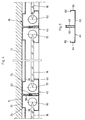
- Fig. 1
- eine Unteransicht auf einen insgesamt vier Felder umfassenden Teilbereich einer erfindungsgemäßen Lichtdecke;
- Fig. 2
- eine Schnittansicht durch die Lichtdecke, gesehen in Richtung der Pfeile II-II in Fig. 1;
- Fig. 3
- eine Schnittansicht durch eine den Trägerprofilen zugeordnete Profilabdeckung;
- Fig. 4
- eine Schnittansicht, gesehen in Richtung der Pfeile IV-IV in Fig. 1;
- Fig. 5
- eine Schnittansicht durch eine den Querprofilen des Verkleidungssystems zugeordnete Profilabdeckung,
- Fig. 6
- eine perspektivische Ansicht einer erfindungsgemäßen Lichtdecke gemäß einem anderen Ausführungsbeispiel, wobei bei dieser Variante die Lichtdecke für von oben her einfallendes Licht durchlässig ist.
Claims (11)
- Anordnung von lichtabstrahlenden plattenförmigen Elementen (110) bei der wenigstens einem plattenförmigen Element wenigstens ein Leuchtmittel (150) zugeordnet ist, welches von der Stirnseite her Licht in das plattenförmige Element hinein abstrahlt und dieses Licht als Streulicht über die Fläche der Platte im rechten Winkel zur Einstrahlrichtung abgegeben wird, wobei diese Anordnung wenigstens zwei vorzugsweise mehrere rasterartig in Längs- und Querreihen angeordnete plattenförmige Elemente der genannten Art umfasst, wobei die plattenförmigen Elemente in ein- oder mehrteiligen Profilrahmen (140) gehaltert sind,
dadurch gekennzeichnet, dass als Leuchtmittel wenigstens eine in die Stirnseite des plattenförmigen Elements einstrahlende Anzahl LED's oder faseroptische Bauelemente vorgesehen sind, wobei die Anordnung selbst eine Raumdecke beziehungsweise Gebäudedecke bildet und wenigstens teilweise im Bereich derjenigen plattenförmigen Elemente (110), bei denen das diesen zugeordnete Leuchtmittel ausgeschaltet ist, für von oberhalb der Anordnung eintretendes natürliches Licht und/oder Kunstlicht durchlässig ist. - Anordnung von lichtabstrahlenden plattenförmigen Elementen nach Anspruch 1, bei der wenigstens eines der plattenförmigen Elemente (110) bei ausgeschaltetem Leuchtmittel (150) in Lichtabstrahlrichtung für natürliches Licht (Tageslicht) durchlässig ist.
- Anordnung von lichtabstrahlenden plattenförmigen Elementen nach einem der Ansprüche 1 oder 2, bei der wenigstens eines der plattenförmigen Elemente (110) weißes Licht abgibt und/oder wenigstens eines der plattenförmigen Elemente farbiges Licht abgibt.
- Anordnung von lichtabstrahlenden plattenförmigen Elementen nach einem der Ansprüche 1 bis 3, dadurch gekennzeichnet, dass die plattenförmigen Elemente (18, 110) durchsichtig beziehungsweise lichtdurchlässig sind und durch eine geeignete Rasterbedruckung oder durch Einlagerung von lichtstreuenden oder reflektierenden Partikeln in die Platte die Abstrahlcharakteristik und die Transparenz der Platte an vorgegebene Anforderungen anpassbar sind.
- Anordnung von lichtabstrahlenden plattenförmigen Elementen nach einem der Ansprüche 1 bis 4, dadurch gekennzeichnet, dass als von der Stirnseite des plattenförmigen Elements her einstrahlende Leuchtmittel eine Anzahl LED's vorgesehen sind, die unterschiedliche Lichtfarben aufweisen, wobei abwechselnd LED's verschiedener Farben in einer Reihe hintereinander angeordnet sind, vorzugsweise jeweils abwechselnd aufeinanderfolgend rote, grüne und blaue LED's und wobei eine Steuerung vorgesehen ist, mittels derer die LED's einzeln oder gruppenweise ansteuerbar und ein- bzw. ausschaltbar sind.
- Anordnung von lichtabstrahlenden plattenförmigen Elementen nach einem der Ansprüche 1 bis 5, dadurch gekennzeichnet, dass eine Anzahl erster Leuchtmittel in Form von LED's oder wenigstens einer Leuchtstofflampe vorgesehen ist, die von einer Stirnseite her Licht in das plattenförmige Element einstrahlen, und dass eine zweite Anzahl Leuchtmittel in Form von LED's oder wenigstens einer Leuchtstofflampe vorgesehen ist, die Licht von der der ersten Anzahl Leuchtmittel gegenüberliegenden Stirnseite her in das plattenförmige Element einstrahlen, wobei eine Steuerung vorgesehen ist, mittels derer die genannten und/oder zweiten Leuchtmittel jeweils einzeln oder gruppenweise ansteuerbar sind.
- Anordnung von lichtabstrahlenden plattenförmigen Elementen nach einem der vorhergehenden Ansprüche, dadurch gekennzeichnet, dass die plattenförmigen Elemente aus einem derartigen Material bestehen bzw. an der lichtabgebenden Seite derartig bedruckt sind, dass aufgrund von Lichtabsorption, Lichtreflektion und/oder Lichtstreuung von der einen Stirnseite her über erste Leuchtmittel eingestrahltes Licht das plattenförmige Element nur etwa bis zur Plattenmitte in weißem oder farbigem Licht erscheinen lässt.
- Anordnung von lichtabstrahlenden plattenförmigen Elementen nach einem der vorhergehenden Ansprüche, dadurch gekennzeichnet, dass eine dritte Anzahl Leuchtmittel in Form von LED's oder wenigstens einer Leuchtstofflampe vorgesehen ist, die von einer dritten Stirnseite her Licht in das plattenförmige Element einstrahlen, wobei die Einstrahlrichtung quer zur Einstrahlrichtung der ersten und/oder zweiten Leuchtmittel erfolgt.
- Anordnung von lichtabstrahlenden plattenförmigen Elementen nach einem der vorhergehenden Ansprüche, dadurch gekennzeichnet, dass die Leuchtmittel so ansteuerbar sind, dass von wenigstens einer Stirnseite her weißes Licht in ein plattenförmiges Element einstrahlbar ist und von wenigstens einer quer zu der ersten Stirnseite verlaufenden zweiten Stirnseite her farbiges Licht in das plattenförmige Element einstrahlbar ist.
- Anordnung von lichtabstrahlenden plattenförmigen Elementen nach einem der vorhergehenden Ansprüche, dadurch gekennzeichnet, dass an allen vier Stirnseiten eines plattenförmigen Elements Leuchtmittel in Form von LED's und/oder Leuchtstofflampen angeordnet sind, die jeweils über eine Steuerung einzeln separat oder in Gruppen ansteuerbar und ein- und ausschaltbar oder in ihrer Helligkeit veränderbar (dimmbar) sind.
- Anordnung von lichtabstrahlenden plattenförmigen Elementen nach einem der vorhergehenden Ansprüche, dadurch gekennzeichnet, dass an einer oder mehrerer Stirnseiten des plattenförmigen Elements eine Anzahl von LED's in den Lichtfarben rot, grün und blau angeordnet sind, die über eine Steuerung gleichzeitig so ansteuerbar sind, dass sie insgesamt weißes Licht in das plattenförmige Element einstrahlen.
Applications Claiming Priority (5)
| Application Number | Priority Date | Filing Date | Title |
|---|---|---|---|
| DE29921689U DE29921689U1 (de) | 1999-12-09 | 1999-12-09 | Lichtabstrahlendes Wand-, Wanddurchbruch-, Decken- und Fassaden-Verkleidungssystem für Gebäude |
| DE29921689U | 1999-12-09 | ||
| DE10039095A DE10039095A1 (de) | 1999-12-09 | 2000-08-07 | Anordnung von lichtabstrahlenden plattenförmigen Elementen |
| DE10039095 | 2000-08-07 | ||
| EP00126262A EP1106914B1 (de) | 1999-12-09 | 2000-12-01 | Anordnung von lichtabstrahlenden plattenförmigen Elementen |
Related Parent Applications (1)
| Application Number | Title | Priority Date | Filing Date |
|---|---|---|---|
| EP00126262A Division EP1106914B1 (de) | 1999-12-09 | 2000-12-01 | Anordnung von lichtabstrahlenden plattenförmigen Elementen |
Publications (2)
| Publication Number | Publication Date |
|---|---|
| EP1176362A1 EP1176362A1 (de) | 2002-01-30 |
| EP1176362B1 true EP1176362B1 (de) | 2004-12-01 |
Family
ID=8082751
Family Applications (1)
| Application Number | Title | Priority Date | Filing Date |
|---|---|---|---|
| EP01123199A Expired - Lifetime EP1176362B1 (de) | 1999-12-09 | 2000-12-01 | Anordnung von lichtabstrahlenden plattenförmigen Elementen |
Country Status (2)
| Country | Link |
|---|---|
| EP (1) | EP1176362B1 (de) |
| DE (6) | DE29921689U1 (de) |
Families Citing this family (17)
| Publication number | Priority date | Publication date | Assignee | Title |
|---|---|---|---|---|
| DE10125433A1 (de) * | 2001-05-25 | 2002-12-05 | Arndt Kuechmann | Beleuchtungseinrichtung |
| CN1313862C (zh) * | 2002-02-10 | 2007-05-02 | 汪秉龙 | Led显示板 |
| DE10223245B4 (de) | 2002-05-21 | 2014-02-27 | Zumtobel Staff Gmbh | Leuchte |
| DE10300662B4 (de) * | 2003-01-10 | 2009-04-09 | Fkn Fassaden Gmbh & Co.Kg | Gebäudefassade |
| ES2244313B1 (es) | 2004-02-16 | 2007-02-16 | Laboratorios Del Dr. Esteve, S.A. | Compuestos de azetidina substituidos, su preparacion y su uso como medicamentos. |
| CN103104837A (zh) * | 2004-06-29 | 2013-05-15 | 皇家飞利浦电子股份有限公司 | 照明系统、照明组件、改善相邻led组件的照明的方法和光孔的用途 |
| DE202007003973U1 (de) * | 2007-03-19 | 2007-06-14 | Patent-Treuhand-Gesellschaft für elektrische Glühlampen mbH | Lichtmodul für ein Glasbausteinrahmensystem und Glasbausteinrahmensystem |
| DE102008047010A1 (de) * | 2008-09-12 | 2010-03-18 | Zumtobel Lighting Gmbh | System zur Aufhellung der Decke eines Raumes |
| BE1018633A5 (nl) * | 2009-01-23 | 2011-05-03 | Glorieux Rik | Samenstel met verlichting, en dak- of wandconstructie omvattende een aantal dergelijke samenstellen. |
| EP2360420B1 (de) * | 2010-02-23 | 2016-01-06 | Stefan Kirner | Modulares Lampensystem für Leuchtdioden |
| DE202011101714U1 (de) * | 2011-06-10 | 2012-09-13 | Novomatic Ag | Beleuchtungsvorrichtung |
| DE102011079611A1 (de) * | 2011-07-22 | 2013-01-24 | Woschko Beteiligungen Gmbh | Leuchte |
| DE102011057097A1 (de) * | 2011-12-28 | 2013-07-04 | Richter Lighting Technologies Gmbh | Decken-Beleuchtungsanordnung |
| DE102012019421A1 (de) | 2012-10-02 | 2014-06-12 | Bartenbach Holding Gmbh | Beleuchtbares Fassadenpaneel |
| DE102012111135A1 (de) * | 2012-11-19 | 2014-05-22 | Uwe Langer | Leuchte und Profilelement für eine Leuchte |
| DE202013105914U1 (de) * | 2013-12-23 | 2015-03-24 | Zumtobel Lighting Gmbh | Leuchte |
| DE102014109856A1 (de) * | 2014-07-14 | 2016-01-14 | Lucem Gmbh | Beleuchtungsinstallation und Verfahren zum Auswechseln mindestens eines Leuchtelements einer Beleuchtungsinstallation |
Family Cites Families (10)
| Publication number | Priority date | Publication date | Assignee | Title |
|---|---|---|---|---|
| FR842566A (fr) * | 1937-08-25 | 1939-06-14 | Lampes Sa | Dispositif d'éclairage électrique |
| DE3719499A1 (de) * | 1987-06-11 | 1988-12-29 | Fandrich Heinz Juergen | Vorrichtung, bestehend aus lichtleitplatten mit erhebungen |
| JPH03216482A (ja) * | 1990-01-20 | 1991-09-24 | Toshiba Corp | エレベータカゴの照明装置 |
| DE4205137A1 (de) * | 1992-02-20 | 1993-08-26 | Willing Gmbh Dr Ing | Scheibenfoermige leuchte |
| DE19502293A1 (de) * | 1995-01-26 | 1996-08-01 | Juergen Manfred Rensch | Beleuchtungseinrichtung |
| US5613751A (en) * | 1995-06-27 | 1997-03-25 | Lumitex, Inc. | Light emitting panel assemblies |
| DE19605371B4 (de) * | 1996-02-14 | 2009-06-18 | Dr. Ing. Willing Gmbh | Scheibenleuchte mit mehreren Lichtleitplatten und gewölbten Abdeckscheiben |
| DE19644875A1 (de) * | 1996-10-29 | 1998-04-30 | Willing Gmbh Dr Ing | Großflächenleuchte |
| DE19718309A1 (de) * | 1997-04-30 | 1998-11-05 | Werbe Fabry Gmbh & Co Kg | Verfahren zur mehrseitigen Einspeisung des Lichts einer paraxial angeordneten Leuchtstoffröhre im mehrere Lichtleiterplatten |
| DE19755658A1 (de) * | 1997-12-15 | 1999-06-17 | Zumtobel Staff Gmbh | Leuchte mit einem scheibenförmigen Lichtleiter |
-
1999
- 1999-12-09 DE DE29921689U patent/DE29921689U1/de not_active Expired - Lifetime
-
2000
- 2000-08-07 DE DE10039095A patent/DE10039095A1/de not_active Withdrawn
- 2000-08-25 DE DE10041850A patent/DE10041850A1/de not_active Withdrawn
- 2000-12-01 DE DE50000481T patent/DE50000481D1/de not_active Expired - Lifetime
- 2000-12-01 EP EP01123199A patent/EP1176362B1/de not_active Expired - Lifetime
- 2000-12-01 DE DE50008838T patent/DE50008838D1/de not_active Expired - Lifetime
- 2000-12-01 DE DE50000551T patent/DE50000551D1/de not_active Expired - Lifetime
Also Published As
| Publication number | Publication date |
|---|---|
| DE10041850A1 (de) | 2001-06-13 |
| DE50000551D1 (de) | 2002-10-31 |
| DE10039095A1 (de) | 2001-08-23 |
| DE50000481D1 (de) | 2002-10-17 |
| EP1176362A1 (de) | 2002-01-30 |
| DE29921689U1 (de) | 2001-04-19 |
| DE50008838D1 (de) | 2005-01-05 |
Similar Documents
| Publication | Publication Date | Title |
|---|---|---|
| EP1346178B1 (de) | Sandwichartiges plattenelement | |
| EP1043542B2 (de) | Beleuchtungsanordnung zur Anbringung an der Decke oder einer Wand eines Raumes | |
| EP1891368B1 (de) | Leuchte mit hauptlichtquelle und zusatzlichtquelle | |
| EP1176362A1 (de) | Anordnung von lichtabstrahlenden plattenförmigen Elementen | |
| DE10064742A1 (de) | Fensterelement | |
| EP1379742B1 (de) | Urbanes möbel mit beleuchteter glasscheibe | |
| DE10231502A1 (de) | Fensterelement | |
| DE10043516A1 (de) | Möbelstück | |
| DE10117203A1 (de) | Urbanes Möbel | |
| WO2002052191A1 (de) | Fensterelement | |
| EP2184628A2 (de) | Leuchte, insbesondere Not-, Rettungs oder Sicherheitsleuchte | |
| DE102007012560B4 (de) | Schaltschrank | |
| EP2388510A2 (de) | Beleuchtungselement | |
| EP1399048B1 (de) | Sanitäre Einrichtung | |
| EP3092439A2 (de) | Leuchtvorrichtung | |
| EP2886950A1 (de) | Leuchte | |
| EP1106915B2 (de) | Anordnung von lichtstrahlenden plattenförmigen Elementen | |
| EP1399692B2 (de) | Bauelement für einen begehbaren und/oder befahrbaren bereich | |
| EP1106914B1 (de) | Anordnung von lichtabstrahlenden plattenförmigen Elementen | |
| DE10064703B4 (de) | Sandwichartiges Plattenelement | |
| EP1035369A2 (de) | Beleuchtungsanordung | |
| DE202006005429U1 (de) | Beleuchtbare Fliese | |
| DE19644875A1 (de) | Großflächenleuchte | |
| DE10117104A1 (de) | Sandwichartiges Plattenelement | |
| EP1619158B1 (de) | Beleuchtung für Aufzugskabine und ein Verfahren zur Beleuchtung einer Kabine |
Legal Events
| Date | Code | Title | Description |
|---|---|---|---|
| PUAI | Public reference made under article 153(3) epc to a published international application that has entered the european phase |
Free format text: ORIGINAL CODE: 0009012 |
|
| AC | Divisional application: reference to earlier application |
Ref document number: 1106914 Country of ref document: EP |
|
| AK | Designated contracting states |
Kind code of ref document: A1 Designated state(s): AT BE CH CY DE DK ES FI FR GB GR IE IT LI LU MC NL PT SE TR |
|
| AX | Request for extension of the european patent |
Free format text: AL;LT;LV;MK;RO;SI |
|
| 17P | Request for examination filed |
Effective date: 20020730 |
|
| AKX | Designation fees paid |
Free format text: AT BE CH CY DE DK ES FI FR GB GR IE IT LI LU MC NL PT SE TR |
|
| 17Q | First examination report despatched |
Effective date: 20030513 |
|
| GRAP | Despatch of communication of intention to grant a patent |
Free format text: ORIGINAL CODE: EPIDOSNIGR1 |
|
| GRAS | Grant fee paid |
Free format text: ORIGINAL CODE: EPIDOSNIGR3 |
|
| GRAA | (expected) grant |
Free format text: ORIGINAL CODE: 0009210 |
|
| AC | Divisional application: reference to earlier application |
Ref document number: 1106914 Country of ref document: EP Kind code of ref document: P |
|
| AK | Designated contracting states |
Kind code of ref document: B1 Designated state(s): AT BE CH CY DE DK ES FI FR GB GR IE IT LI LU MC NL PT SE TR |
|
| PG25 | Lapsed in a contracting state [announced via postgrant information from national office to epo] |
Ref country code: IT Free format text: LAPSE BECAUSE OF FAILURE TO SUBMIT A TRANSLATION OF THE DESCRIPTION OR TO PAY THE FEE WITHIN THE PRESCRIBED TIME-LIMIT;WARNING: LAPSES OF ITALIAN PATENTS WITH EFFECTIVE DATE BEFORE 2007 MAY HAVE OCCURRED AT ANY TIME BEFORE 2007. THE CORRECT EFFECTIVE DATE MAY BE DIFFERENT FROM THE ONE RECORDED. Effective date: 20041201 Ref country code: FI Free format text: LAPSE BECAUSE OF FAILURE TO SUBMIT A TRANSLATION OF THE DESCRIPTION OR TO PAY THE FEE WITHIN THE PRESCRIBED TIME-LIMIT Effective date: 20041201 Ref country code: SE Free format text: LAPSE BECAUSE OF FAILURE TO SUBMIT A TRANSLATION OF THE DESCRIPTION OR TO PAY THE FEE WITHIN THE PRESCRIBED TIME-LIMIT Effective date: 20041201 Ref country code: CY Free format text: LAPSE BECAUSE OF FAILURE TO SUBMIT A TRANSLATION OF THE DESCRIPTION OR TO PAY THE FEE WITHIN THE PRESCRIBED TIME-LIMIT Effective date: 20041201 Ref country code: NL Free format text: LAPSE BECAUSE OF FAILURE TO SUBMIT A TRANSLATION OF THE DESCRIPTION OR TO PAY THE FEE WITHIN THE PRESCRIBED TIME-LIMIT Effective date: 20041201 Ref country code: TR Free format text: LAPSE BECAUSE OF FAILURE TO SUBMIT A TRANSLATION OF THE DESCRIPTION OR TO PAY THE FEE WITHIN THE PRESCRIBED TIME-LIMIT Effective date: 20041201 Ref country code: FR Free format text: LAPSE BECAUSE OF NON-PAYMENT OF DUE FEES Effective date: 20041201 Ref country code: IE Free format text: LAPSE BECAUSE OF FAILURE TO SUBMIT A TRANSLATION OF THE DESCRIPTION OR TO PAY THE FEE WITHIN THE PRESCRIBED TIME-LIMIT Effective date: 20041201 Ref country code: GB Free format text: LAPSE BECAUSE OF FAILURE TO SUBMIT A TRANSLATION OF THE DESCRIPTION OR TO PAY THE FEE WITHIN THE PRESCRIBED TIME-LIMIT Effective date: 20041201 |
|
| REG | Reference to a national code |
Ref country code: GB Ref legal event code: FG4D Free format text: NOT ENGLISH |
|
| REG | Reference to a national code |
Ref country code: CH Ref legal event code: EP |
|
| REG | Reference to a national code |
Ref country code: IE Ref legal event code: FG4D Free format text: GERMAN |
|
| PG25 | Lapsed in a contracting state [announced via postgrant information from national office to epo] |
Ref country code: BE Free format text: LAPSE BECAUSE OF NON-PAYMENT OF DUE FEES Effective date: 20041231 Ref country code: MC Free format text: LAPSE BECAUSE OF NON-PAYMENT OF DUE FEES Effective date: 20041231 |
|
| REF | Corresponds to: |
Ref document number: 50008838 Country of ref document: DE Date of ref document: 20050105 Kind code of ref document: P |
|
| PG25 | Lapsed in a contracting state [announced via postgrant information from national office to epo] |
Ref country code: LU Free format text: LAPSE BECAUSE OF NON-PAYMENT OF DUE FEES Effective date: 20050201 |
|
| PG25 | Lapsed in a contracting state [announced via postgrant information from national office to epo] |
Ref country code: DK Free format text: LAPSE BECAUSE OF FAILURE TO SUBMIT A TRANSLATION OF THE DESCRIPTION OR TO PAY THE FEE WITHIN THE PRESCRIBED TIME-LIMIT Effective date: 20050301 Ref country code: GR Free format text: LAPSE BECAUSE OF FAILURE TO SUBMIT A TRANSLATION OF THE DESCRIPTION OR TO PAY THE FEE WITHIN THE PRESCRIBED TIME-LIMIT Effective date: 20050301 |
|
| PG25 | Lapsed in a contracting state [announced via postgrant information from national office to epo] |
Ref country code: ES Free format text: LAPSE BECAUSE OF FAILURE TO SUBMIT A TRANSLATION OF THE DESCRIPTION OR TO PAY THE FEE WITHIN THE PRESCRIBED TIME-LIMIT Effective date: 20050312 |
|
| NLV1 | Nl: lapsed or annulled due to failure to fulfill the requirements of art. 29p and 29m of the patents act | ||
| GBV | Gb: ep patent (uk) treated as always having been void in accordance with gb section 77(7)/1977 [no translation filed] |
Effective date: 20041201 |
|
| BERE | Be: lapsed |
Owner name: EMDE, THOMAS Effective date: 20041231 Owner name: POHL, HEINRICH ROBERT Effective date: 20041231 |
|
| REG | Reference to a national code |
Ref country code: IE Ref legal event code: FD4D |
|
| PLBI | Opposition filed |
Free format text: ORIGINAL CODE: 0009260 |
|
| 26 | Opposition filed |
Opponent name: INSTA ELEKTRO GMBH Effective date: 20050718 |
|
| PLAX | Notice of opposition and request to file observation + time limit sent |
Free format text: ORIGINAL CODE: EPIDOSNOBS2 |
|
| PLBB | Reply of patent proprietor to notice(s) of opposition received |
Free format text: ORIGINAL CODE: EPIDOSNOBS3 |
|
| EN | Fr: translation not filed | ||
| RAP2 | Party data changed (patent owner data changed or rights of a patent transferred) |
Owner name: KONINKLIJKE PHILIPS ELECTRONICS N.V. |
|
| RIN2 | Information on inventor provided after grant (corrected) |
Inventor name: KONINKLIJKE PHILIPS ELECTRONICS N.V. |
|
| PLCK | Communication despatched that opposition was rejected |
Free format text: ORIGINAL CODE: EPIDOSNREJ1 |
|
| APBP | Date of receipt of notice of appeal recorded |
Free format text: ORIGINAL CODE: EPIDOSNNOA2O |
|
| APAH | Appeal reference modified |
Free format text: ORIGINAL CODE: EPIDOSCREFNO |
|
| APBQ | Date of receipt of statement of grounds of appeal recorded |
Free format text: ORIGINAL CODE: EPIDOSNNOA3O |
|
| BERE | Be: lapsed |
Owner name: *EMDE THOMAS Effective date: 20041231 Owner name: *POHL HEINRICH ROBERT Effective date: 20041231 |
|
| PG25 | Lapsed in a contracting state [announced via postgrant information from national office to epo] |
Ref country code: PT Free format text: LAPSE BECAUSE OF NON-PAYMENT OF DUE FEES Effective date: 20050501 |
|
| APBU | Appeal procedure closed |
Free format text: ORIGINAL CODE: EPIDOSNNOA9O |
|
| PLBN | Opposition rejected |
Free format text: ORIGINAL CODE: 0009273 |
|
| STAA | Information on the status of an ep patent application or granted ep patent |
Free format text: STATUS: OPPOSITION REJECTED |
|
| 27O | Opposition rejected |
Effective date: 20100309 |
|
| REG | Reference to a national code |
Ref country code: DE Ref legal event code: R082 Ref document number: 50008838 Country of ref document: DE Representative=s name: FRITZ, EDMUND, DIPL.-CHEM., DE |
|
| REG | Reference to a national code |
Ref country code: DE Ref legal event code: R081 Ref document number: 50008838 Country of ref document: DE Owner name: KONINKLIJKE PHILIPS N.V., NL Free format text: FORMER OWNER: KONINKLIJKE PHILIPS ELECTRONICS N.V., EINDHOVEN, NL Effective date: 20140331 Ref country code: DE Ref legal event code: R082 Ref document number: 50008838 Country of ref document: DE Representative=s name: FRITZ, EDMUND, DIPL.-CHEM., DE Effective date: 20140331 Ref country code: DE Ref legal event code: R081 Ref document number: 50008838 Country of ref document: DE Owner name: PHILIPS LIGHTING HOLDING B.V., NL Free format text: FORMER OWNER: KONINKLIJKE PHILIPS ELECTRONICS N.V., EINDHOVEN, NL Effective date: 20140331 Ref country code: DE Ref legal event code: R082 Ref document number: 50008838 Country of ref document: DE Representative=s name: MEISSNER BOLTE PATENTANWAELTE RECHTSANWAELTE P, DE Effective date: 20140331 |
|
| REG | Reference to a national code |
Ref country code: DE Ref legal event code: R082 Ref document number: 50008838 Country of ref document: DE Representative=s name: MEISSNER BOLTE PATENTANWAELTE RECHTSANWAELTE P, DE Ref country code: DE Ref legal event code: R081 Ref document number: 50008838 Country of ref document: DE Owner name: PHILIPS LIGHTING HOLDING B.V., NL Free format text: FORMER OWNER: KONINKLIJKE PHILIPS N.V., EINDHOVEN, NL |
|
| PGFP | Annual fee paid to national office [announced via postgrant information from national office to epo] |
Ref country code: AT Payment date: 20191223 Year of fee payment: 20 |
|
| PGFP | Annual fee paid to national office [announced via postgrant information from national office to epo] |
Ref country code: DE Payment date: 20191230 Year of fee payment: 20 |
|
| PGFP | Annual fee paid to national office [announced via postgrant information from national office to epo] |
Ref country code: CH Payment date: 20200113 Year of fee payment: 20 |
|
| REG | Reference to a national code |
Ref country code: DE Ref legal event code: R071 Ref document number: 50008838 Country of ref document: DE |
|
| REG | Reference to a national code |
Ref country code: CH Ref legal event code: PL |
|
| REG | Reference to a national code |
Ref country code: AT Ref legal event code: MK07 Ref document number: 284004 Country of ref document: AT Kind code of ref document: T Effective date: 20201201 |