EP1177403B1 - Device by ice storage for the discharging of ice - Google Patents
Device by ice storage for the discharging of ice Download PDFInfo
- Publication number
- EP1177403B1 EP1177403B1 EP00919172A EP00919172A EP1177403B1 EP 1177403 B1 EP1177403 B1 EP 1177403B1 EP 00919172 A EP00919172 A EP 00919172A EP 00919172 A EP00919172 A EP 00919172A EP 1177403 B1 EP1177403 B1 EP 1177403B1
- Authority
- EP
- European Patent Office
- Prior art keywords
- ice
- floor
- elements
- floor element
- floor elements
- Prior art date
- Legal status (The legal status is an assumption and is not a legal conclusion. Google has not performed a legal analysis and makes no representation as to the accuracy of the status listed.)
- Expired - Lifetime
Links
- 238000003860 storage Methods 0.000 title claims abstract description 59
- 238000007599 discharging Methods 0.000 title abstract description 3
- 238000010276 construction Methods 0.000 claims abstract description 5
- 230000033001 locomotion Effects 0.000 claims description 8
- 230000005540 biological transmission Effects 0.000 claims description 6
- 239000000969 carrier Substances 0.000 abstract description 10
- XLYOFNOQVPJJNP-UHFFFAOYSA-N water Substances O XLYOFNOQVPJJNP-UHFFFAOYSA-N 0.000 abstract description 2
- 230000014759 maintenance of location Effects 0.000 description 6
- 241000251468 Actinopterygii Species 0.000 description 4
- 238000004519 manufacturing process Methods 0.000 description 4
- 230000032258 transport Effects 0.000 description 4
- 238000001816 cooling Methods 0.000 description 3
- 230000000694 effects Effects 0.000 description 2
- 238000007710 freezing Methods 0.000 description 2
- 230000008014 freezing Effects 0.000 description 2
- 238000000034 method Methods 0.000 description 2
- 238000007790 scraping Methods 0.000 description 2
- 230000001154 acute effect Effects 0.000 description 1
- 230000015572 biosynthetic process Effects 0.000 description 1
- 230000007547 defect Effects 0.000 description 1
- 230000001419 dependent effect Effects 0.000 description 1
- 230000003031 feeding effect Effects 0.000 description 1
- 238000012432 intermediate storage Methods 0.000 description 1
- 238000002844 melting Methods 0.000 description 1
- 230000008018 melting Effects 0.000 description 1
- 230000000284 resting effect Effects 0.000 description 1
- 239000004576 sand Substances 0.000 description 1
- 238000007789 sealing Methods 0.000 description 1
Images




Classifications
-
- F—MECHANICAL ENGINEERING; LIGHTING; HEATING; WEAPONS; BLASTING
- F25—REFRIGERATION OR COOLING; COMBINED HEATING AND REFRIGERATION SYSTEMS; HEAT PUMP SYSTEMS; MANUFACTURE OR STORAGE OF ICE; LIQUEFACTION SOLIDIFICATION OF GASES
- F25C—PRODUCING, WORKING OR HANDLING ICE
- F25C5/00—Working or handling ice
- F25C5/02—Apparatus for disintegrating, removing or harvesting ice
- F25C5/04—Apparatus for disintegrating, removing or harvesting ice without the use of saws
-
- F—MECHANICAL ENGINEERING; LIGHTING; HEATING; WEAPONS; BLASTING
- F25—REFRIGERATION OR COOLING; COMBINED HEATING AND REFRIGERATION SYSTEMS; HEAT PUMP SYSTEMS; MANUFACTURE OR STORAGE OF ICE; LIQUEFACTION SOLIDIFICATION OF GASES
- F25C—PRODUCING, WORKING OR HANDLING ICE
- F25C5/00—Working or handling ice
- F25C5/20—Distributing ice
- F25C5/24—Distributing ice for storing bins
-
- Y—GENERAL TAGGING OF NEW TECHNOLOGICAL DEVELOPMENTS; GENERAL TAGGING OF CROSS-SECTIONAL TECHNOLOGIES SPANNING OVER SEVERAL SECTIONS OF THE IPC; TECHNICAL SUBJECTS COVERED BY FORMER USPC CROSS-REFERENCE ART COLLECTIONS [XRACs] AND DIGESTS
- Y10—TECHNICAL SUBJECTS COVERED BY FORMER USPC
- Y10S—TECHNICAL SUBJECTS COVERED BY FORMER USPC CROSS-REFERENCE ART COLLECTIONS [XRACs] AND DIGESTS
- Y10S241/00—Solid material comminution or disintegration
- Y10S241/27—Pill or tablet crushers
Definitions
- This invention relates to a device by an ice storage or other room for producing and storing ice, in which the ice is scraped loose and let out for further transportation by means of a conveyor.
- Ice of this kind is used extensively in the fish industry, where fish is cooled and maintains its quality when shipped over short and long distances.
- the concrete industry represents another large field of application, where it is often desired to cool sand before cementing.
- the top of the ice mass in an ice storage in the form of the upper ice layer, represents ice which stems from the water which was last cooled and transformed to ice.
- the advantageous principle "first in, first out” cannot be followed, and with time ice of the lower layers will become old and of deteriorated quality. This is of particular importance in the fish industry, where, reasonably, "fresh ice” is desired as cover for fish.
- the known plant with chain drive at the bottom of the ice storage has, by one short wall of the storage, an ice-chipping device which chips off ice from an adjacent ice mass surface. The resulting chipped-off pieces of ice subsequently fall down to an underlying auger. Also this known plant is restricted to smaller sizes and capacities, about 10 - 20 tons of ice per day.
- a variant of said manually operated ice storage is the so-called “minor ice storage”, in which loosened, comminuted ice is taken out through hatch openings at the side of the ice storage and into the utility crate.
- This variant of a plant is still in use and represents a small investment, but it is laborious and only suitable in connection with a minor ice storage capacity, a daily production of ice of about 10 - 15 tons.
- the object of the present invention has therefore been to alleviate or reduce to a substantial degree, by simple and cheap means, the defects, drawbacks and limitations of application of known technique, and thus provide simple improving devices for ice storages, in which a novel and distinctive floor construction enables convenient outlet of ice from the bottom, whereby the ice first formed is the first to be discharged from the ice storage.
- a special object aimed at through the invention has been to attain an ice storage floor structure consisting of individual elements of multi-purpose function, which work, because of their shape, in particular their cross-sectional shape, in combination with the movement of the individual elements adjusted in pairs, as an ice-chipping and releasing means, and which together may form, in one preferred embodiment, when the ice within the storage is in its storage condition, a sufficiently tight ice storage floor, which is free from ice-leakage, and which constitutes the outlet opening of the ice storage in its active position.
- the floor of an ice storage known in itself, where ice is produced and stored, for example in the form of cubes or as crushed plate-ice, is constituted according to the invention of elongate, parallel, rod-/pipe-shaped elements which are preferably all provided with distinct edge portions, which may be formed through the cross-sectional shape (cornered/polygonal cross-section) of the elements and/or through strip-shaped carriers extending in the longitudinal direction of the floor elements and distributed in the circumferential direction thereof.
- the rod-/pipe-shaped ice storage floor elements are supported individually for rotation about their respective longitudinal axes. It is the rotational support of the floor elements that is effected individually; said elements may be driven by one common drive mechanism, for example a gear transmission, whereby each floor element has a gear arranged thereto, the gears being identical and engaging adjacent gears.
- a gear transmission whereby each floor element has a gear arranged thereto, the gears being identical and engaging adjacent gears.
- the outermost (left-hand) gear is arranged to rotate clockwise.
- the associated floor element is also rotated clockwise.
- the direction of rotation of the outermost but one gear is of course contrary and for the associated ice storage floor element also anti-clockwise.
- the elongate, straight, rod-/pipe-shaped ice storage floor elements may have such a diameter and be spaced so that, adapted to the transversal dimension of the strip-shaped carrier means, in a given rotational position of each floor element relative to the adjacent element(s), said elements will together form a tight ice storage floor.
- rod/pipe elements that have a cornered/polygonal cross-section this applies when adjacent edge portions are brought into an approximately tightening abutment against one another, and by floor elements provided with carriers, when adjacent strip-shaped carrier means engage one another.
- relatively narrowly spaced tooth-/spike-like chipping and carrying means may be used, for example arranged in groups in longitudinal and transversal rows or placed more randomly, distributed at random across the parallel rod-/pipe-shaped elements.
- Such carrier teeth or spikes may be formed and positioned so that by the individual rotational movements of the floor elements, they may be continuous, or the angle of rotation may be limited, for example to 180° in either direction, whereby every second rotational movement will constitute a return movement in relation to the feeding rotational movement.
- Such a rotation through a half rotation clockwise and then a half back turn, anti-clockwise is the easiest way of adapting the floor element to the desire for a tight ice storage floor in the idle ice-storing position thereof.
- the external circumferential shape of the ice storage floor elements may vary, and for example, as mentioned, square pipes or pipes with an external polygonal circumferential shape, for example with an octagonal or hexagonal outer circumferential shape, may be used.
- the floor elements are sized and supported in the adjacent frame or wall structure, so that in its different conditions the ice storage floor can withstand the weight of the ice resting thereon.
- the present invention entails substantial simplifications in the storing, detaching/chipping, releasing and transport of ice, and provides for a more hygienic storing, letting out and transport of ice from the ice storage to the place of consumption.
- This novel system is suitable for all types of ice, and there is no need for additional cooling, as with the known plants with augers at the bottom.
- the system according to the invention has few moving parts, which makes it very reliable in operation. By changing the rotational movement and/or speed of the individual floor elements, a desired adjustability may be achieved.
- the ice which is produced in ice storages of the kind in question is normally shaped as cubes or is found in the form of crushed plate-ice.
- the ice storage of this known plant is placed in a cold storage, possibly equipped with a separate cooling device and insulated walls. This is a very elaborate and very expensive solution, and the present invention represents great simplifications relative to this, which will provide considerable financial savings.
- Figs. 1 and 2 in which the reference numerals 10 and 12 in Fig. 1 identify opposite side walls of a schematically visualized ice storage, in which the ceiling wall is identified by 14 and the "floor" generally by 16.
- the floor structure 16 which forms the object of the present invention, it being formed of a suitable number, i.e. two or more, of elongate ice storage floor elements, generally identified by 18, extending parallel to one another in the longitudinal direction of the ice storage 10,12,14,16.
- the elongate elements or profiles are conveniently rod-like or tubular.
- the ice storage floor 16 may have a horizontal extent or form a relatively small, acute angle with a horizontal plane.
- Each individual tubular floor element 18 is rotationally supported individually, in a manner known in itself, dependent on surface area, cross-sectional profile, span, weight of the ice etc.
- Fig. 2 shows a longitudinal floor element section which forms only part of the full length of the floor element.
- This floor element 18 is of tubular shape.
- An axle is identified by 19.
- the element 18 is externally provided with entirely or approximately radially projecting carrier means 20, which may extend, in this embodiment, throughout the length of the floor element 18.
- a key way in the end portion of the axle 19 is identified by 21.
- Fig. 2 of continuously extending carrier means these may be placed, on adjacent floor elements 18, to engage one another in a sealing manner by partial rotation through an angle of 90°, for the formation of an essentially tight ice storage floor 16.
- the consecutive carrier strips 20 may possibly be replaced by more tooth-/spike-like carriers (not shown) which will have - like the carrier strips 20 - the intended chipping/scraping effect on the lowermost layer of the above-lying ice mass.
- the floor elements 18 rotate in pairs, two and two, in opposite directions of rotation, towards one another, in order to feed down ice mass, torn and loosened by the carriers 20, in the intermediate slots between the floor elements 18.
- Fig. 3 is suggested the use of a gear transmission on an ice storage floor (hidden behind the gears), in which each floor element has a concentric gear 22, 24, 26 arranged thereto (the gear on the left is hidden behind a drive engine 28), which are equally big and engage adjacent wheels.
- the hidden gear on the extreme left is assumed to be driven clockwise by the engine 28, so that the immediately following gear 22 is rotated anti-clockwise.
- the last two gears 24, 26 of this row of interconnected gears are rotated in the same manner, i.e. towards one another from the level of the axis downwards, to feed down chipped off mass of ice to an underlying conveyor belt 30.
- the belt/chain is run in a "sinusoidal" path, so that the chain wheels 34 and 36 and associated floor elements 18 on the one side, and the chain wheels 38 and 40 and associated floor elements 18 on the other side are brought to rotate towards one another through opposite directions of rotation, from the axis level downwards, in order to feed down chipped off ice mass to an underlying conveyor belt 30.
- An engine 42 with a small driving chain wheel 44 wedged to the output driving shaft thereof, is mounted on a frame portion somewhat above the chain wheels 34, 36, 38 and 40.
- the chain 32 is laid over this drive wheel 44 and from there on about a tightening wheel 46 which also serves to guide the chain 32 in towards the upper circumferential portion of the chain wheel 34.
- the chain 32 gets to attack a larger arc of the chain wheel 34 than if the chain 32 was passed directly from the drive wheel 44 to the upper circumferential portion of the chain wheel 34.
- the profiled floor elements 18 may be supported/driven for continuous rotation in one and same direction, towards each other in pairs in opposite directions, or the support/driving method may be based on pitched rotation (preferably 180° in opposite directions, down and then back up into start position) of each floor element.
- the ice discharging rate could be adjusted as required.
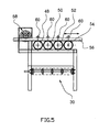
- each of, for example, four parallel horizontally extending ice storage floor elements is provided with a transmissions means in the form of a cylindrical gear 48, 50, 52 and 54 engaged and driven by a shared motorized pitch rod 56.
- a transmissions means in the form of a cylindrical gear 48, 50, 52 and 54 engaged and driven by a shared motorized pitch rod 56.
- Above-lying, parallel, horizontally extending, freely rotational support and guide rollers 60 retain the displaceable pitch rod 56 in a driving engagement with each of the gears 48, 50, 52, 54.
- the reference numeral 58 is generally identified a drive engine, on whose output shaft is wedged a gear with small teeth that engage corresponding teeth spaces on a toothed portion of the pitch rod 56.
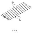
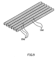
- Figs. 6 - 9 show some different cross-sectional shapes (with and without carrier/chipping strips 20) for ice storage floor elements, in which;
- Fig. 6 shows a circular cross-section with eight carrier/chipping strips 20a (central angle 45°). This second type of element is identified by 18a.
- Fig. 7 the cross-sectional shape of the floor elements 18b is regularly octagonal, and here no carrier strips are used.
- the octagonal cross-section provides distinct, longitudinal edge portions of excellent chipping and carrying properties.
- each floor element 18c is provided with two carriers 20c.
- Fig. 9 the cross-sectional shape is hexagonal, which provides, as far as it goes, the desired distinct longitudinal edge portions of chipping and carrying properties by the rotational motions of the floor elements 18d.
- the floor elements it has been preferred to fit two carrier strips 28d.
Landscapes
- Engineering & Computer Science (AREA)
- Mechanical Engineering (AREA)
- Thermal Sciences (AREA)
- General Engineering & Computer Science (AREA)
- Physics & Mathematics (AREA)
- Warehouses Or Storage Devices (AREA)
- Devices That Are Associated With Refrigeration Equipment (AREA)
- Beverage Vending Machines With Cups, And Gas Or Electricity Vending Machines (AREA)
- Carbon And Carbon Compounds (AREA)
- Confectionery (AREA)
- Freezing, Cooling And Drying Of Foods (AREA)
- Electrical Discharge Machining, Electrochemical Machining, And Combined Machining (AREA)
- Load-Engaging Elements For Cranes (AREA)
- Distillation Of Fermentation Liquor, Processing Of Alcohols, Vinegar And Beer (AREA)
Priority Applications (1)
| Application Number | Priority Date | Filing Date | Title |
|---|---|---|---|
| DK00919172T DK1177403T3 (da) | 1999-05-07 | 2000-04-11 | Indretning ved islager til afgivelse af is |
Applications Claiming Priority (3)
| Application Number | Priority Date | Filing Date | Title |
|---|---|---|---|
| NO992220 | 1999-05-07 | ||
| NO992220A NO307716B1 (no) | 1999-05-07 | 1999-05-07 | Anordning ved islager for utmating av is |
| PCT/NO2000/000115 WO2000068623A1 (en) | 1999-05-07 | 2000-04-11 | Device by ice storage for the discharging of ice |
Publications (2)
| Publication Number | Publication Date |
|---|---|
| EP1177403A1 EP1177403A1 (en) | 2002-02-06 |
| EP1177403B1 true EP1177403B1 (en) | 2004-06-16 |
Family
ID=19903308
Family Applications (1)
| Application Number | Title | Priority Date | Filing Date |
|---|---|---|---|
| EP00919172A Expired - Lifetime EP1177403B1 (en) | 1999-05-07 | 2000-04-11 | Device by ice storage for the discharging of ice |
Country Status (15)
| Country | Link |
|---|---|
| US (1) | US7137582B1 (da) |
| EP (1) | EP1177403B1 (da) |
| JP (1) | JP4424859B2 (da) |
| AT (1) | ATE269523T1 (da) |
| AU (1) | AU3988500A (da) |
| CA (1) | CA2373141C (da) |
| DE (1) | DE60011610T2 (da) |
| DK (1) | DK1177403T3 (da) |
| ES (1) | ES2222896T3 (da) |
| IS (1) | IS2102B (da) |
| NO (1) | NO307716B1 (da) |
| PL (1) | PL194331B1 (da) |
| PT (1) | PT1177403E (da) |
| RU (1) | RU2237221C2 (da) |
| WO (1) | WO2000068623A1 (da) |
Families Citing this family (6)
| Publication number | Priority date | Publication date | Assignee | Title |
|---|---|---|---|---|
| CN102226611A (zh) * | 2011-05-13 | 2011-10-26 | 冰人制冰系统设备(重庆)有限公司 | 履带式储冰库及其出冰方法 |
| US10837690B2 (en) | 2017-12-08 | 2020-11-17 | Midea Group Co., Ltd. | Refrigerator icemaking system with tandem storage bins and/or removable dispenser recess |
| US11525615B2 (en) | 2017-12-08 | 2022-12-13 | Midea Group Co., Ltd. | Refrigerator icemaking system with tandem storage bins and/or removable dispenser recess |
| US10852046B2 (en) | 2018-12-10 | 2020-12-01 | Midea Group Co., Ltd. | Refrigerator with door-mounted fluid dispenser |
| US11293680B2 (en) | 2019-06-14 | 2022-04-05 | Midea Group Co., Ltd. | Refrigerator with multiple ice movers |
| DE102024203949A1 (de) * | 2024-04-26 | 2025-11-20 | The Phizz Company GmbH | Modulare Eisproduktionsanlage, Fahrzeug zur Verwendung mit einer Eisproduktionsanlage und System umfassend eine modulare Eisproduktionsanlage und wenigstens ein Fahrzeug |
Family Cites Families (12)
| Publication number | Priority date | Publication date | Assignee | Title |
|---|---|---|---|---|
| US2524815A (en) * | 1945-01-22 | 1950-10-10 | Flakice Corp | Ice making |
| US3514964A (en) * | 1969-02-10 | 1970-06-02 | Gen Electric | Icemaker with improved ice storage receptacle |
| US3744263A (en) * | 1970-11-09 | 1973-07-10 | D Corley | Recirculation system for meltdown water from an ice storage compartment |
| US3825158A (en) * | 1973-05-16 | 1974-07-23 | W Morris | Cube ice storage bin with disturber bars |
| US3892337A (en) | 1973-11-21 | 1975-07-01 | Reynolds Products | Bin ice delivery mechanism |
| US4008740A (en) * | 1974-09-03 | 1977-02-22 | Chermack Robert W | Dispensing apparatus for filling drinking containers |
| US4333612A (en) * | 1979-11-27 | 1982-06-08 | Kyoei Zoki Kabushiki Kaisha | Apparatus for storage of ice |
| US4632280A (en) | 1984-09-25 | 1986-12-30 | White Consolidated Industries, Inc. | Ice dispensing mechanism |
| CA1307242C (en) | 1986-12-18 | 1992-09-08 | John R. Bradbury | Apparatus and method for storing and dispensing particulate ice |
| US4788830A (en) | 1987-03-13 | 1988-12-06 | Schreiner R Alan | Apparatus for bulk ice making and dispensing |
| RU2108065C1 (ru) * | 1994-06-08 | 1998-04-10 | Петербургский научно-исследовательский институт травматологии и ортопедии им.Р.Р.Вредена | Способ противоболевой блокады при патологии спинного мозга и позвоночника |
| WO1997029330A1 (en) * | 1996-02-12 | 1997-08-14 | Tmo Enterprises Limited | Dispensing apparatus |
-
1999
- 1999-05-07 NO NO992220A patent/NO307716B1/no not_active IP Right Cessation
-
2000
- 2000-04-11 PT PT00919172T patent/PT1177403E/pt unknown
- 2000-04-11 DE DE60011610T patent/DE60011610T2/de not_active Expired - Lifetime
- 2000-04-11 RU RU2001133016/12A patent/RU2237221C2/ru not_active IP Right Cessation
- 2000-04-11 US US09/959,789 patent/US7137582B1/en not_active Expired - Fee Related
- 2000-04-11 PL PL00352371A patent/PL194331B1/pl unknown
- 2000-04-11 WO PCT/NO2000/000115 patent/WO2000068623A1/en not_active Ceased
- 2000-04-11 AT AT00919172T patent/ATE269523T1/de not_active IP Right Cessation
- 2000-04-11 DK DK00919172T patent/DK1177403T3/da active
- 2000-04-11 CA CA002373141A patent/CA2373141C/en not_active Expired - Fee Related
- 2000-04-11 JP JP2000617371A patent/JP4424859B2/ja not_active Expired - Fee Related
- 2000-04-11 EP EP00919172A patent/EP1177403B1/en not_active Expired - Lifetime
- 2000-04-11 ES ES00919172T patent/ES2222896T3/es not_active Expired - Lifetime
- 2000-04-11 AU AU39885/00A patent/AU3988500A/en not_active Abandoned
-
2001
- 2001-11-07 IS IS6149A patent/IS2102B/is unknown
Also Published As
| Publication number | Publication date |
|---|---|
| NO992220A (no) | 2000-05-15 |
| NO307716B1 (no) | 2000-05-15 |
| IS6149A (is) | 2001-11-07 |
| NO992220D0 (no) | 1999-05-07 |
| IS2102B (is) | 2006-05-15 |
| PL194331B1 (pl) | 2007-05-31 |
| PL352371A1 (en) | 2003-08-25 |
| US7137582B1 (en) | 2006-11-21 |
| ES2222896T3 (es) | 2005-02-16 |
| DE60011610D1 (de) | 2004-07-22 |
| JP4424859B2 (ja) | 2010-03-03 |
| EP1177403A1 (en) | 2002-02-06 |
| RU2237221C2 (ru) | 2004-09-27 |
| ATE269523T1 (de) | 2004-07-15 |
| DE60011610T2 (de) | 2005-07-28 |
| AU3988500A (en) | 2000-11-21 |
| DK1177403T3 (da) | 2004-10-25 |
| CA2373141C (en) | 2007-02-27 |
| WO2000068623A1 (en) | 2000-11-16 |
| JP2002544463A (ja) | 2002-12-24 |
| PT1177403E (pt) | 2004-11-30 |
| CA2373141A1 (en) | 2000-11-16 |
Similar Documents
| Publication | Publication Date | Title |
|---|---|---|
| EP1177403B1 (en) | Device by ice storage for the discharging of ice | |
| CN212133003U (zh) | 双螺旋速冻设备 | |
| CN101405206B (zh) | 用于加工原木的方法及装置 | |
| US4042343A (en) | Fire log process and apparatus | |
| EP3710385B1 (en) | Continuous product-processing apparatus and method for cleaning with product repositioning | |
| US4464910A (en) | Ice harvesting machine | |
| RU2001133016A (ru) | Устройство при льдохранилище, предназначенное для отгрузки льда | |
| EP3612621A1 (fr) | Installation de malterie en continu | |
| JPH088601Y2 (ja) | 育苗箱への軽量育苗培土供給装置 | |
| KR200470500Y1 (ko) | 얼음공급기용 반출스크류 부하 경감장치 | |
| RU2142347C1 (ru) | Устройство для фракционного разделения древесных отходов | |
| CN207305962U (zh) | 一种螺旋式水产品速冻装置 | |
| CN221396209U (zh) | 一种料仓分料器 | |
| JPH08562U (ja) | 育苗箱への軽量育苗培土供給装置 | |
| CN216592722U (zh) | 一种回转窑喂料螺旋进料口的防积料装置 | |
| JPS60213631A (ja) | 砕氷の貯蔵庫 | |
| DE3305155A1 (de) | Foerdervorrichtung zum auflockern, dosieren und austragen von spaenen, faserigen und mehligen substanzen aus einem lagersilo | |
| KR200199163Y1 (ko) | 마늘파종기 | |
| KR960004000Y1 (ko) | 땅속 작물 수확기 | |
| JPH0347464Y2 (da) | ||
| AU2007354501A1 (en) | Ice storage system for an ice machine | |
| CN121867134A (zh) | 冰鲜杂鱼饲料投喂装置 | |
| SU1097760A1 (ru) | Рабочий орган террасера | |
| PL235762B1 (pl) | Płuczka rozcierająca do oczyszczania surowców mineralnych | |
| JPS628372B2 (da) |
Legal Events
| Date | Code | Title | Description |
|---|---|---|---|
| PUAI | Public reference made under article 153(3) epc to a published international application that has entered the european phase |
Free format text: ORIGINAL CODE: 0009012 |
|
| 17P | Request for examination filed |
Effective date: 20011108 |
|
| AK | Designated contracting states |
Kind code of ref document: A1 Designated state(s): AT BE CH CY DE DK ES FI FR GB GR IE IT LI LU MC NL PT SE |
|
| AX | Request for extension of the european patent |
Free format text: AL;LT;LV;MK;RO;SI |
|
| GRAP | Despatch of communication of intention to grant a patent |
Free format text: ORIGINAL CODE: EPIDOSNIGR1 |
|
| GRAS | Grant fee paid |
Free format text: ORIGINAL CODE: EPIDOSNIGR3 |
|
| GRAA | (expected) grant |
Free format text: ORIGINAL CODE: 0009210 |
|
| AK | Designated contracting states |
Kind code of ref document: B1 Designated state(s): AT BE CH CY DE DK ES FI FR GB GR IE IT LI LU MC NL PT SE |
|
| PG25 | Lapsed in a contracting state [announced via postgrant information from national office to epo] |
Ref country code: BE Free format text: LAPSE BECAUSE OF FAILURE TO SUBMIT A TRANSLATION OF THE DESCRIPTION OR TO PAY THE FEE WITHIN THE PRESCRIBED TIME-LIMIT Effective date: 20040616 Ref country code: CH Free format text: LAPSE BECAUSE OF FAILURE TO SUBMIT A TRANSLATION OF THE DESCRIPTION OR TO PAY THE FEE WITHIN THE PRESCRIBED TIME-LIMIT Effective date: 20040616 Ref country code: AT Free format text: LAPSE BECAUSE OF FAILURE TO SUBMIT A TRANSLATION OF THE DESCRIPTION OR TO PAY THE FEE WITHIN THE PRESCRIBED TIME-LIMIT Effective date: 20040616 Ref country code: LI Free format text: LAPSE BECAUSE OF FAILURE TO SUBMIT A TRANSLATION OF THE DESCRIPTION OR TO PAY THE FEE WITHIN THE PRESCRIBED TIME-LIMIT Effective date: 20040616 |
|
| REG | Reference to a national code |
Ref country code: GB Ref legal event code: FG4D |
|
| REG | Reference to a national code |
Ref country code: CH Ref legal event code: EP |
|
| REF | Corresponds to: |
Ref document number: 60011610 Country of ref document: DE Date of ref document: 20040722 Kind code of ref document: P |
|
| REG | Reference to a national code |
Ref country code: IE Ref legal event code: FG4D |
|
| REG | Reference to a national code |
Ref country code: SE Ref legal event code: TRGR |
|
| REG | Reference to a national code |
Ref country code: DK Ref legal event code: T3 |
|
| REG | Reference to a national code |
Ref country code: GR Ref legal event code: EP Ref document number: 20040403192 Country of ref document: GR |
|
| LTIE | Lt: invalidation of european patent or patent extension |
Effective date: 20040616 |
|
| REG | Reference to a national code |
Ref country code: PT Ref legal event code: SC4A Free format text: AVAILABILITY OF NATIONAL TRANSLATION Effective date: 20040915 |
|
| REG | Reference to a national code |
Ref country code: CH Ref legal event code: PL |
|
| REG | Reference to a national code |
Ref country code: ES Ref legal event code: FG2A Ref document number: 2222896 Country of ref document: ES Kind code of ref document: T3 |
|
| ET | Fr: translation filed | ||
| PG25 | Lapsed in a contracting state [announced via postgrant information from national office to epo] |
Ref country code: CY Free format text: LAPSE BECAUSE OF FAILURE TO SUBMIT A TRANSLATION OF THE DESCRIPTION OR TO PAY THE FEE WITHIN THE PRESCRIBED TIME-LIMIT Effective date: 20050411 Ref country code: LU Free format text: LAPSE BECAUSE OF NON-PAYMENT OF DUE FEES Effective date: 20050411 |
|
| PLBE | No opposition filed within time limit |
Free format text: ORIGINAL CODE: 0009261 |
|
| STAA | Information on the status of an ep patent application or granted ep patent |
Free format text: STATUS: NO OPPOSITION FILED WITHIN TIME LIMIT |
|
| PG25 | Lapsed in a contracting state [announced via postgrant information from national office to epo] |
Ref country code: MC Free format text: LAPSE BECAUSE OF NON-PAYMENT OF DUE FEES Effective date: 20050430 |
|
| 26N | No opposition filed |
Effective date: 20050317 |
|
| PG25 | Lapsed in a contracting state [announced via postgrant information from national office to epo] |
Ref country code: IT Free format text: LAPSE BECAUSE OF NON-PAYMENT OF DUE FEES Effective date: 20080411 |
|
| PGRI | Patent reinstated in contracting state [announced from national office to epo] |
Ref country code: IT Effective date: 20110616 |
|
| REG | Reference to a national code |
Ref country code: DE Ref legal event code: R082 Ref document number: 60011610 Country of ref document: DE Representative=s name: PATENTANWAELTE UND RECHTSANWALT DR. WEISS, ARA, DE Ref country code: DE Ref legal event code: R082 Ref document number: 60011610 Country of ref document: DE Representative=s name: PATENTANWAELTE UND RECHTSANWALT WEISS, ARAT & , DE |
|
| REG | Reference to a national code |
Ref country code: FR Ref legal event code: PLFP Year of fee payment: 17 |
|
| PGFP | Annual fee paid to national office [announced via postgrant information from national office to epo] |
Ref country code: PT Payment date: 20160302 Year of fee payment: 17 Ref country code: GR Payment date: 20160323 Year of fee payment: 17 |
|
| PGFP | Annual fee paid to national office [announced via postgrant information from national office to epo] |
Ref country code: NL Payment date: 20160420 Year of fee payment: 17 |
|
| PGFP | Annual fee paid to national office [announced via postgrant information from national office to epo] |
Ref country code: DE Payment date: 20160420 Year of fee payment: 17 Ref country code: IE Payment date: 20160419 Year of fee payment: 17 Ref country code: FI Payment date: 20160415 Year of fee payment: 17 |
|
| PGFP | Annual fee paid to national office [announced via postgrant information from national office to epo] |
Ref country code: IT Payment date: 20160321 Year of fee payment: 17 Ref country code: FR Payment date: 20160330 Year of fee payment: 17 Ref country code: SE Payment date: 20160418 Year of fee payment: 17 |
|
| PGFP | Annual fee paid to national office [announced via postgrant information from national office to epo] |
Ref country code: ES Payment date: 20170210 Year of fee payment: 18 |
|
| PGFP | Annual fee paid to national office [announced via postgrant information from national office to epo] |
Ref country code: GB Payment date: 20170512 Year of fee payment: 18 |
|
| REG | Reference to a national code |
Ref country code: DE Ref legal event code: R119 Ref document number: 60011610 Country of ref document: DE |
|
| REG | Reference to a national code |
Ref country code: NL Ref legal event code: MM Effective date: 20170501 |
|
| REG | Reference to a national code |
Ref country code: IE Ref legal event code: MM4A |
|
| REG | Reference to a national code |
Ref country code: FR Ref legal event code: ST Effective date: 20171229 |
|
| PG25 | Lapsed in a contracting state [announced via postgrant information from national office to epo] |
Ref country code: FI Free format text: LAPSE BECAUSE OF NON-PAYMENT OF DUE FEES Effective date: 20170411 Ref country code: NL Free format text: LAPSE BECAUSE OF NON-PAYMENT OF DUE FEES Effective date: 20170501 Ref country code: FR Free format text: LAPSE BECAUSE OF NON-PAYMENT OF DUE FEES Effective date: 20170502 Ref country code: DE Free format text: LAPSE BECAUSE OF NON-PAYMENT OF DUE FEES Effective date: 20171103 |
|
| PG25 | Lapsed in a contracting state [announced via postgrant information from national office to epo] |
Ref country code: PT Free format text: LAPSE BECAUSE OF NON-PAYMENT OF DUE FEES Effective date: 20171011 Ref country code: GR Free format text: LAPSE BECAUSE OF NON-PAYMENT OF DUE FEES Effective date: 20171103 Ref country code: SE Free format text: LAPSE BECAUSE OF NON-PAYMENT OF DUE FEES Effective date: 20170412 |
|
| PG25 | Lapsed in a contracting state [announced via postgrant information from national office to epo] |
Ref country code: IE Free format text: LAPSE BECAUSE OF NON-PAYMENT OF DUE FEES Effective date: 20170411 |
|
| PG25 | Lapsed in a contracting state [announced via postgrant information from national office to epo] |
Ref country code: IT Free format text: LAPSE BECAUSE OF NON-PAYMENT OF DUE FEES Effective date: 20170411 |
|
| GBPC | Gb: european patent ceased through non-payment of renewal fee |
Effective date: 20180411 |
|
| PGFP | Annual fee paid to national office [announced via postgrant information from national office to epo] |
Ref country code: DK Payment date: 20181030 Year of fee payment: 19 |
|
| PG25 | Lapsed in a contracting state [announced via postgrant information from national office to epo] |
Ref country code: GB Free format text: LAPSE BECAUSE OF NON-PAYMENT OF DUE FEES Effective date: 20180411 |
|
| REG | Reference to a national code |
Ref country code: ES Ref legal event code: FD2A Effective date: 20190911 |
|
| PG25 | Lapsed in a contracting state [announced via postgrant information from national office to epo] |
Ref country code: ES Free format text: LAPSE BECAUSE OF NON-PAYMENT OF DUE FEES Effective date: 20180412 |
|
| REG | Reference to a national code |
Ref country code: DK Ref legal event code: EBP Effective date: 20190430 |
|
| PG25 | Lapsed in a contracting state [announced via postgrant information from national office to epo] |
Ref country code: DK Free format text: LAPSE BECAUSE OF NON-PAYMENT OF DUE FEES Effective date: 20190430 |